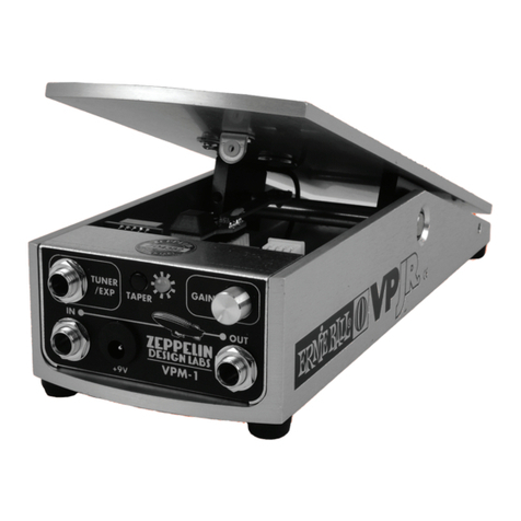
Zeppelin Design Labs VPM-1 User manual

VPM-1
VOLUME PEDAL MOD

2
VPM-1
VOLUME PEDAL MOD FOR ERNIE BALL VP JR
Assembly Manual
© 2020 ZEPPELIN DESIGN LABS. NO PART OF THIS DOCUMENT MAY BE REPRODUCED WITHOUT WRITTEN PERMISSION FROM THE AUTHOR. ZEPPELIN DESIGN LABS TAKES
NO RESPONSIBILITY FOR ANY DAMAGE OR HARM THAT MAY COME TO ANYONE OR ANYTHING THROUGH THEIR PRODUCTS.
033020
INTRODUCTION ...................................................................................................... 3
ABOUT THE ERNIE BALL VOLUME PEDAL............................................................... 3
HOW THE VPM-1 WORKS................................................................................... 4
WHAT’S IN THE BOX................................................................................................ 6
WHAT YOU WILL NEED .......................................................................................... 11
TOOLS ............................................................................................................. 11
SUPPLIES .......................................................................................................... 11
POPULATING THE PRINTED CIRCUIT BOARDS ........................................................... 11
MAIN BOARD................................................................................................... 14
SENSOR BOARD............................................................................................... 31
STEREO UPGRADE BOARD ................................................................................ 34
EXPRESSION UPGRADE BOARD ......................................................................... 37
PREPARING THE ERNIE BALL VP JR............................................................................ 40
PUTTING IT ALL TOGETHER ..................................................................................... 42
CHASSIS .......................................................................................................... 42
POTENTIOMETER BLOCK................................................................................... 45
MAGNET ......................................................................................................... 47
MAIN BOARD & CHASSIS ................................................................................. 49
SETTING UP STEREO CONFIGURATION................................................................... 51
CALIBRATING THE VPM-1........................................................................................ 53
WARNING: THIS IS NOT A BEGINNERS SOLDERING PROJECT. THE COMPACT SIZE AND
SMALL FOOT PRINTS OF THE COMPONENTS ON THE VPM-1 CIRCUIT BOARD CAN BE
DIFFICULT TO SOLDER. WE HIGHLY RECOMMEND COMPACT CIRCUIT BOARD SOLDERING
EXPERIENCE AS A PREREQUISITE FOR THIS KIT. ZEPPELIN DESIGN LABS IS NOT RESPONSIBLE
FOR THE SUCCESS OF YOUR KIT.

3
INTRODUCTION
ABOUT THE ERNIE BALL VOLUME PEDAL
The Ernie Ball volume pedal has been around since 1975. The
chassis of these early volume pedals was originally made
from two pieces of angle iron welded together, which
earned them a reputation of being extremely robust.
Later, the chassis was replaced with a solid aluminum
extrusion that greatly reduced the weight while retaining
the structural integrity of the original. A somewhat novel
approach was used to alter the value of a volume potentiometer
incorporating a string and a set of springs, reminiscent of the tuning
wheel on older analog radios. Over the years, some minor mechanical and
electrical design changes have been made, but the general concept of how these
pedals work has remained the same.
The Ernie Ball volume pedal has a lot of great
features. Being made out of solid aluminum, it is
nearly indestructible. The string and spring mechanism
for turning the potentiometer creates a very smooth
response in volume. Also, the placement of the axle on
the treadle makes for a very comfortable pedal action.
It’s no wonder that the Ernie Ball volume pedal is the
most popular volume pedal in the world.
But for all its great features, there are a couple of
serious down-sides to this pedal. Since the audio
signal is sent straight through the potentiometer, any
problems with the potentiometer are directly translated
to the audio signal. This means that if the potentiometer gets dirty or worn out, the audio signal can
sound scratchy. Also, the passive nature of this pedal means that the electrical load of the potentiometer
can have drastic tonal effects on the signal. Any stray capacitance in the guitar cable or anywhere
else in the system will create a RC (resistance-capacitance) filter when coupled with the given value of
the potentiometer. When the potentiometer is turned all the way up, to a higher resistance, this effect is
less noticeable; but when the potentiometer is turned to a lower resistance, the high frequencies in the
audible range start to become attenuated. This is what causes the “tone suck” effect when adjusting
the volume control on a passive guitar. Many musicians have resorted to adding a buffer pedal before
their passive volume pedal to help rectify this issue.
Another serious issue with these Ernie Ball volume pedals involves the string and spring mechanism
for adjusting the potentiometer. Over time, the string can actually stretch and cause the action of the
pedal to be off. This often manifests itself in the potentiometer not getting turned all the way in one
direction or the other, which prevents the audio signal from getting as loud or as quiet as it should.


4
Eventually the string will wear completely out and break. Most long-term Ernie Ball volume pedal users
have experienced this, and usually at the most inopportune times. Few things make a guitarist more
frustrated than not being able to turn up their volume before a solo.
These limitations of the stock Ernie Ball volume pedal have driven a lot of frustrated guitarists to create
their own mods for this pedal. Mostly these mods just incorporate a buffer or boost circuit into the
pedal to counteract the “tone suck” effects of the passive potentiometer. Here at Zeppelin Design Labs,
we have been fans of the Ernie Ball VP Jr for years, and have developed our own mod. Born out of
a frustration with its limitations and a passion for its potential, we have created what we think is the
“mother of all volume pedal mods.” We’ve improved upon every limitation of the Ernie Ball VP Jr while
retaining all the great characteristics that make it the most popular volume pedal of all time.
HOW THE VPM-1 WORKS
Our first goal with this mod was to eliminate the string. We replaced it with a magnetic distance sensor,
called a Hall effect sensor. A magnet is affixed to the underside of the treadle and the Hall effect sensor
outputs a voltage proportional to the distance to the magnet. See Figure 1, page 5. This voltage is fed
into the ADC (analog to digital converter) of a microcontroller. A microcontroller is a tiny computer
capable of receiving and sending voltages. This microcontroller manipulates the brightness of the LEDs
inside a pair of optocouplers, based on the voltage from the Hall effect sensor. These optocouplers
each contain a light-dependent resistor (LDR) which work together to control the volume of the audio
signal. The audio path is completely analog, but it is digitally controlled through the LEDs in the
optocouplers. Because the audio is digitally controlled, we can easily change many parameters of how
the signal is processed. First, we’ve incorporated five different tapers (or sweeps, or response curves),

5
including logarithmic, linear, and reverse logarithmic. Next, we’ve included a “reverse” feature that
allows you to reverse the treadle action. Finally, one of the most useful features of this mod is the ability
to program the pedal positions for minimum and maximum volume, which allows you to set the active
range of the pedal’s sweep.
The VPM-1 comes standard in mono configuration, but stereo configuration is available with a small
add-on upgrade board. In the stereo configuration, the VPM-1 can operate as either a traditional
stereo volume pedal where both audio channels get louder and quieter together, or it can operate
as a “pan” pedal, where one audio channel gets louder as the other gets quieter. Pan mode enables
the user to pan between two different signals. Another add-on upgrade board gives the VPM-1 the
ability to be used as an expression pedal, with programmable settings to accommodate the different
expression jack wiring configurations found on a wide range of effects pedals.
For a complete discussion of the VPM-1’s features and controls, please see the VPM-1 Owner’s Guide,
available from www.zeppelindesignlabs.com.
If you ordered the Stereo upgrade or Expression upgrade with your VPM-1 kit, you will find their parts
in their own labeled packages. This assembly manual describes the assembly of these upgrade boards
right along side the main board. If you didn’t opt for either of these upgrades, just ignore the assembly
instructions for these boards.
Figure 1: VPM-1 Block Diagram

6
WHAT’S IN THE BOX
Table 1: VPM-1 Standard Kit Bill Of Materials (BOM) is a complete parts list of everything that should
be present in your kit, followed by photos of each part. Print the BOM and carefully go through the kit,
identifying every part. Please read about the proper handling of integrated circuits (ICs) in paragraph
4 on page 21 before removing anything from the silver static-protective bag. Note that some of the
components are difficult to tell apart. Compare them carefully with the photos. Besides verifying that
nothing is missing, this will acquaint you with the parts and their names. If ANYTHING is missing, first
double-check; we double-checked before sealing the box at our lab! If it’s still missing, EMAIL US right
parts in the mail to you as soon as possible. If you lose or damage
anything, we will be glad to sell you replacements. The unusual or
custom components can be ordered directly from us (contact info@
zeppelindesignlabs.com). For more common parts, like resistors,
capacitors, or screws, you may prefer to go to a local electronics
or hardware store.
If you ordered either the Stereo or Expression Upgrades
with your VPM-1 kit, you will have an extra parts bag or two.
Throughout this assembly manual, these upgrade components will
be installed along side the other components with appropriate notes. Figure 3 is a picture of the Stereo
Upgrade kit contents, and Table 2 is its BOM. Likewise, Figure 4 shows the Expression Upgrade kit and
Table 3 is its BOM. As with the main board parts, please carefully go through each kit making sure all
the parts are present before you start assembling anything.
TIP: Empty the parts
of the kit into a bowl, NOT
onto the cluttered workbench, or
onto the living room carpet! This
will protect you from losing tiny
parts.
Figure 2: VPM-1 Standard Kit Contents

7
Table 1: VPM-1 Standard Kit Bill Of Materials
ZDL Part # Description Notes Qty
CB-01-42 Hookup Wire, 2.5" (7cm) x 2 wires 1
CB-90-13 Heat Shrink Tube, 3/16" x 1-1/2" (5x40mm) For Optocouplers 1
CB-06-10 Ribbon Cable, 4 wire x 10cm 1
CH-10-32 Steel Chassis 1
CP-10-08 Electrolytic Capacitor 220uF C6 1
CP-30-18 Ceramic Capacitor 100nF C1 on Sensor Board 1
CP-10-01 Electrolytic Cap, Radial 5x11mm 100uF C19, C20 2
CP-12-10 Electrolytic Cap, Radial 5x11mm 1uF Bipolar C4A, C5 2
CP-20-16 Film Capacitor 100nF C1A, C2A, C3A 3
DI-30-51 LED, 5mm RGB 1
DI-30-52 LED, 5mm Green For Optocouplers 2
FA-93-35 Lock washer, Split Ring 3.5mm 2
FA-12-15 Magnet 1
HD-32-21 Knob, Knurled, Aluminum, 10mm 1
HD-40-01 ¼" TRS Audio Jack, Vertical Mount J1, J2, J3 3
HD-40-12 DC Power Jack, Panel Mount 1
HD-10-11 Rubber Foot, Square 1
HE-60-02 Jumper, Female, 2 pin For Tuner Jumper 1
HE-20-01 Male Header Pins 16
IC-81-76 Voltage Boost Converter, ICL7660S U4 1
IC-80-50 Voltage Regulator, 78L05 U5 1
PC-11-01 VPM-1 Main PCB 1
PC-11-02 Sensor PCB 1
PL-10-11 VPM-1 Faceplate Sticker 1
PL-10-90 Serial Number Sticker 1
PT-35-10 Stereo Potentiometer, 100K, PC Vertical Mount VR1 1
SN-30-10 Light Dependent Resistor (LDR)* For Optocouplers 2*
SN-50-01 Hall Effect Sensor Magnet Sensor 1
ST-60-59 LED Standoff, M5 x 19mm 1
SW-30-25 Tact Switch, 6 x 6 x 25mm S1 1
SW-60-23 Switch Cap, Black 1
SW-45-50 DIP Switch, 5 Position S2 1
TP-30-21 Tape, Double Sided, 15mm Circle 1
DC-20-21 Calibration Card 1
*NOTE: If you bought the Stereo upgrade kit, you will find a set of 4 matched LDRs packed with the
upgrade, and no LDRs packed with the standard kit.

8
CB-01-42 CB-90-13 CB-06-10 CH-10-32 C6
C1 C19,C20 C4A,C5 C1A,C2A,C3A DI-30-51
DI-30-52 FA-93-35 FA-12-15 HD-32-21 HD-40-01
HD-40-12 HD-10-11 HE-60-02 HE-20-01 U4
U5 PC-11-01 PC-11-02 PL-10-11 PL-10-90
PT-35-10 SN-30-10 SN-50-01 ST-60-59 SW-30-25
SW-60-23 S2 TP-30-21 DC-20-21

9
Figure 3: VPM-1 Stereo Upgrade Contents
Table 2: VPM-1 Stereo Upgrade Bill of Materials
ZDL Part # Description Notes Qty
CB-90-13 Heat Shrink Tube, 3/16" x 1-1/2" (5x40mm) For Optocouplers 1
CP-12-10 Electrolytic Cap, Radial 5x11mm 1uF Bipolar C4B 1
CP-20-16 Film Capacitor 100nF C1B, C2B, C3B 3
DI-30-52 LED, 5mm Green For Optocouplers 2
HE-20-01 Male Header Pins 33
HE-20-14 Female Header, 4 Pin 2
HE-20-17 Female Header, 7 Pin 1
HE-60-02 Jumper, Female, 2 pin 7
PC-11-04 Stereo Upgrade PCB 1
SN-30-10 Light Dependent Resistor (ldr) For Optocouplers 4
CB-90-13 C4B C1B, C2B, C3B DI-30-52 HE-20-01
HE-20-14 HE-20-17 HE-60-02 PC-11-04 SN-30-10

10
Figure 4: VPM-1 Expression Upgrade Contents
Table 3: VPM-1 Expression Upgrade Bill of Materials
ZDL Part # Description Notes Qty
CP-30-18 Ceramic Capacitor 100nF C25 1
DI-90-01 Zener Diode, 5.1V D2 1
HE-20-01 Male Header Pins 9
HE-20-14 Female Header, 4 Pin 1
HE-20-15 Female Header, 5 Pin 1
HE-25-08 IC Socket, Dip 8 1
IC-48-01 IC, Digital Potentiometer, MCP41050 U3, 50K ohms 1
IC-48-02 IC, Digital Potentiometer, MCP41010 U3, 10K ohms 1
PC-11-03 Expression Upgrade PCB 1
SW-45-50 DIP Switch, 5 Position S2 1
C25 D2 HE-20-01 HE-20-14 HE-20-15
HE-25-08 IC-48-01 IC-48-01 PC-11-03 SW-45-50

11
WHAT YOU WILL NEED
Here’s everything you will need to build the VPM-1 kit.
TOOLS
1. #2 Philips screw driver
2. Flat head screw driver
3. Needle nose pliers
4. 1/2” (12mm) and 9/16” (15mm) sockets and driver (for audio jack nuts and DC jack nuts)
5. Soldering iron* (not a soldering gun, or a “cold heat” iron), good quality, 15-50 watt, with a good small-
sized tip, conical or chisel shape. One with a temperature control and a stand* is best.
6. Wet sponge* or dry solder-cleaning pad
7. Wire strippers* capable of stripping 22awg wire.
8. Flush cutters* or small diagonal cutters
9. X-Acto®knife or hobby knife
10. Ruler
11. Electronics tweezers*, not entirely necessary, but very helpful for holding small parts.
12. Clamp or vise to hold the printed circuit board while soldering (optional, but handy)
13. Solder sucker* or solder braid (optional, but very handy if you have to remove or repair any components!)
14. Digital multimeter*, not necessary for assembly, but may be handy for troubleshooting.
SUPPLIES
1. Solder*, 60/40 rosin core, the smaller diameter the better (we prefer .032” diameter). Make sure it’s good
quality; we prefer Kester brand, but most brands will work fine.
2. Isopropyl alcohol and cleaning rag
3. Scotch®or painter’s tape
4. Super glue; We prefer the “gel” type because it’s easy to control, but any type will work.
*Available from www.zeppelindesignlabs.com.
POPULATING THE PRINTED CIRCUIT BOARDS
Your work space should be well-lit, well-ventilated, and disposable; that is, don’t work on the nice dining
room table! Work on a utility surface that you can burn, drill and scratch. A piece of ¼” tempered
masonite, or a chunk of MDF, makes an excellent surface if you don’t have a utility work bench.
CAUTION: Solder fumes are not healthy for you. The fumes consist of vaporized flux,
which can irritate your nose, lungs, and even your skin. You MUST work in a space where
the air drifts away from you as you work, so fumes do not rise straight into your face.
CAUTION: Solder residue usually contains lead, which is poisonous if you ingest it. Do not
breathe the fumes, do not eat the supplies, wash your hands after you handle solder, and
sweep and wipe up your work space after EVERY USE.

12
Your VPM-1 standard kit contains two printed circuit boards (PCBs): the main board and the sensor
board. The Stereo upgrade and Expression upgrade kits each contain one additional board. We will
start with the main board. About half of the components will be installed on each side of the main
board. The white silk-screen printing indicates which side of the PCB each component should be inserted
through. Each component will then be soldered in place on the other side of the board. Because of the
tight spacing on these circuit boards, it’s important to not over-apply solder to the joints; otherwise it’s
easy to create solder bridges between two components that aren’t supposed to be connected. Proper
technique for installing and soldering components to a circuit board is demonstrated through several
great resources on Instructables and YouTube under the search “PCB soldering tutorial.” The general
procedure consists of the following:
1. Install the part on the component side of the board, by threading the wire leads through the
appropriate holes in the board. For your convenience, the board has silk screen outlines indicating
where the components should be placed, along with text indicating the part number and the
component value.
2. Hold the component in place with your finger and turn the board over.
3. Gently bend the leads out at about 45 degrees to keep the component from falling out.
4. Install all of one type of component, bending each of the leads as they are installed.
5. Flip the board over solder-side-up, and solder all of the components in one pass. In soldering, the
key is to place the iron’s tip on both the component lead and the pad on the circuit board at the
same time in order to heat them both up simultaneously, once they are sufficiently heated, then
add solder onto that joint.
6. Clip the leads off with small diagonal cutters, right at the solder joint.
You will notice that we have installed several components on the PCB already. These components
are surface mounted, which are a little more difficult to solder. The square chip in the middle of the
board has been pre-programed with the software your VPM-1 needs to run. If you are interested in
changing the way your VPM-1 operates then you may want to look into modifying this software and
re-programming the chip. Instructions for this process can be found in the VPM-1 Owner’s Guide.

13
Figure 5: Main Board Component Values and Locations
Main Board Top:
Main Board Bottom:

14
Let’s begin!
MAIN BOARD
1. Tact Switch (S1): First off, use a tiny half-drop of super glue to attach the little button cap (SW-60-
23) to the switch actuator (1,2). Make sure the cap is pressed down tight to the tip of the actuator.
Now set the switch aside to allow the glue to fully cure before you install it later.
1 2
2. Capacitors: This kit contains three types of capacitors (or caps): film, electrolytic, and ceramic. The
little yellow ceramic cap will be installed on the sensor board later. For now we will install the red
film caps and cylindrical electrolytic caps on the main PCB, one type at a time.
a. Film Capacitors: There are 3 film capacitors in the VPM-1 (C1A,C2A,C3A). They are100nF
(.1uF) in value and labeled “104J”. These caps are not polarized, meaning the leads can go
into either hole. Install these caps on the front of the board (3,4) and bend the leads on the
back so they don’t fall out (5). Solder each lead and then clip them off right above the solder
joint (6). Save two of these leads to use as jumpers later on in the assembly process.
134
56

15
b. Electrolytic Capacitors: We will use 3 different electrolytic caps on the main board. There
is one 220uF cap (C6), two 100uF caps (C19, C20), and two non-polarized (bipolar) 1uF
caps (C4A, C5). You can read their values on their casings. Caps C6, C19 and C20 ARE
POLARIZED: there is a right way and a wrong way to install them. If you get it wrong, your
pedal will not work and the capacitor might burst. The white stripe on the case indicates
the side of the cap with the shorter, negative lead. The longer lead is positive. The longer,
positive lead goes into the hole with a square pad; the shorter, negative, white-stripe lead
goes into the hole with the round pad (7).
STRIPE = NEGATIVE = SHORTER LEAD = ROUND PAD
NO STRIPE = POSITIVE = LONGER LEAD = SQUARE PAD
Make sure you orient these caps properly (7, 8)! For reference, “Figure 5: Main Board
Component Values and Locations” on page 13 has little red plus signs (+) on the positive
pads. C4A and C5 are NOT polarized, which is why there is no white stripe on their
casing. You can install these in either direction. Bend the leads out on the back as you install
each one (10). Solder (11) and clip each lead (12).
7 8
9 10
11 12

16
3. Headers: The main board uses male and female headers of various sizes in up to 17 different
locations, depending on which upgrade boards you are installing, if any. If you are not installing
any upgrade boards, you will install male headers in 3 different locations, and no female headers.
The Expression upgrade adds 2 female headers to the main board. Those headers are packaged
with the Expression upgrade. The Stereo upgrade adds 3 female headers and 9 male headers to
the main board. Those parts are packaged with the Stereo upgrade.
PLEASE NOTE: Your kit contains the necessary number of header pins in one or
more sections. If you have more than one section, be mindful when you break them
apart into the individual lengths required for the build. Plan ahead so that you do not
end up with a few pieces of one-pin header. This would be annoying.
We’ll start with the 3 male headers that go on the main board, common to all VPM-1 versions.
a. ISP header: By installing a 2x3 header array, you create an ISP (in-system programming)
port. This is a little socket that enables you to plug a cable into your VPM-1 and upload (or
“flash”) new software onto the control chip (aka the microcontroller unit, or MCU). The
microcontroller in this kit comes pre-programmed with the software needed to make your
VPM-1 work, but you can mod or tweak the software and re-program the chip, if you are
into that sort of thing. See the VPM-1 Owner’s Guide for more information about this.
Carefully break two pieces with three pins each off of the row of header pins. You can use
your fingers to do this (13). Insert the two pieces in the pads marked “ISP” (14). The short
pins go through the board; the long pins point up. Make sure the bottoms of the headers are
flat against the circuit board.
13 14

17
Tack one pin down with solder while you hold the header in from the top (15,16). Once
each row has been tacked on, you can solder the other pins in place (17).
15 16
17
b. Q1 Header: This header uses a 4-pin ribbon cable to connect to the sensor board. Carefully
break off 4 pins from the row of header pins. Solder this 4 pin header to the Q1 location
(18-20).
18 19
20

18
c. J4 (TUNER JMP): This header is used in conjunction with a pin jumper to connect the audio
signal to the tuner out jack. Carefully break off 2 pins from the row of header pins and install
it in like manner (21-23). If you are NOT installing the Expression upgrade then place the
jumper on the header; if you ARE installing the Expression upgrade, leave the jumper off.
21 22
23
d. If you are NOT installing the Stereo upgrade, then at this time use a couple of your cut-
off leads as hard-wired jumpers. Locations J5 and J6 need to be jumped. Use your pliers
or tweezers to bend the leads into U-shapes (24) and install them into J5 and J6 (25,26).
Solder them on the back side and clip the leads (27).
24 25
26 27

19
e. Expression upgrade female headers: If you are installing the Expression upgrade, dig out the
two female headers from the expression kit bag. One of them will have 4 pins and one will
have 5 pins. There are no locations printed on the board for these, so just use the pictures as
reference. Make sure the bottom of these headers are flush with the board and are standing
straight up as you solder them.
28 29
30 31
32 33

20
f. Stereo upgrade female headers: If you are installing the Stereo upgrade then dig out the
three female headers from the stereo kit bag. There are two 4-pin headers and one 7-pin
header. Once again, there are no markings on the board for these parts so use the pictures
as reference. As you solder them in make sure they are exactly perpendicular to the PCB.
Also make sure the bottom of the headers are flush with the surface of the PCB.
34 35
36
g. Stereo upgrade male headers: If you are installing the Stereo upgrade you need to install
nine sets of 2-pin male headers on the main PCB. The Stereo upgrade kit comes with two
lengths of male header. Break off 9 sets of 2 pins each, starting with a piece of header that
has an even number of pins. (This will ensure you do not end up with a 1-pin header.) Solder
them in the locations: CAL1, CAL2, CAL3, CAL4,CAL5,CAL6,CAL7, J5, and J6.
37 38
39
Other manuals for VPM-1
1
Table of contents
Other Zeppelin Design Labs Music Pedal manuals

Zeppelin Design Labs
Zeppelin Design Labs QUAVERATO User manual

Zeppelin Design Labs
Zeppelin Design Labs NOISETTE User manual

Zeppelin Design Labs
Zeppelin Design Labs QUAVERATO User manual

Zeppelin Design Labs
Zeppelin Design Labs ALTURA MKII Plus User manual

Zeppelin Design Labs
Zeppelin Design Labs VPM-1 User manual

Zeppelin Design Labs
Zeppelin Design Labs QUAVERATO MIDI MOD User manual