Media MicroComputer NAS-9601 User manual

NAS-9601
User Manual
Version 1.0
Published October 2017

Important Safety Instructions
Pay close attention to the following safety instructions before performing any of
the operation. Basic safety precautions should be followed to protect yourself from
harm and the product from damage:
• Operation of the product should be carried out by suitably trained, qualied, and
certied personnel only to avoid risk of injury from electrical shock or energy hazard.
• Disconnect the power cord from the wall outlet when installing or removing main
system components, such as the motherboard and power supply unit.
• Place the system on a stable and at surface.
• Use extreme caution when working with high-voltage components.
• When handling parts, use a grounded wrist strap designed to prevent static discharge.
• Keep the area around the system clean and clutter-free.
• Keep all components and printed circuit boards (PCBs) in their antistatic bags when
not in use.
• Handle a board by its edges only; do not touch its components, peripheral chips,
memory modules or contacts.

Contents
Chapter 1 Introduction 1
1.1 Package Contents 1
1.2 Product Specications 2
Chapter 2 Product Overview 4
2.1 Front View 4
2.2 Rear View 5
2.3 Inside View 6
Chapter 3 Hardware Installation 7
3.1 How to Remove the Top Case 7
3.2 How to Remove the Bottom Case 7
3.3 How to Install the Mini PCIe Card 8
3.4 How to Install the Wi Module 9
3.5 How to Install the M.2_SSD Module 10
3.6 How to Install the 2.5-inch Hard Drive 12
3.7 How to Install the Memory Modules 14
Chapter 4 Software and Utilities Operation 16
4.1 Installing Drivers 16
Chapter 5 UEFI SETUP UTILITY 17
5.1 Introduction 17
5.1.1 UEFI Menu Bar 17
5.1.2 Navigation Keys 18
5.2 Main Screen 18

5.3 Advanced Screen 19
5.3.1 CPU Conguration 20
5.3.2 Chipset Conguration 21
5.3.3 Storage Conguration 22
5.3.4 Super IO Conguration 23
5.3.5 ACPI Conguration 24
5.3.6 USB Conguration 25
5.3.7 Trusted Computing 26
5.4 Hardware Health Event Monitoring Screen 27
5.5 Security Screen 28
5.6 Boot Screen 29
5.7 Exit Screen 31
NAS-9601
PB 1
English
Chapter 1 Introduction
1.1 Package Contents
• NAS-9601 Barebone System with:
NAS-9601 Chassis
Motherboard (pre-installed)
*e barebone system does not include memory, hard drive and mSATA SSD.
• 1 x Power Adapter (12V) & Power Plug
• 2 x M.2 Screws
• 1 x VGA Cable
• 1 x RJ45 to COM Cable
• Support CD
• Quick Installation Guide
Because the hardware specications might be updated, the content of this documentation
will be subject to change without notice.
If any items are missing or appear damaged, contact your authorized dealer.

2 3
English
1.2 Product Specications
NAS-9601 Barebone
CPU Intel® Celeron Braswell SoCSupports Hyper-reading
Technology Default N3160 Quad core 6W processor
OS N/A
Chipset Intel® N3160 SoC
Memory Supports Single Channel DDR3L up to 1600 MHz, 1 x SO-
DIMM slot, Max. 8GB
HDD
1 x M.2 Slot (Key M), supports
type 2242/2280 M.2 for SATA only
Supports 1 x 2.5" SATA HDD
LAN Gigabit LAN
WiFi Optional
Audio N/A
Front I/O N/A
Rear I/O 2 x USB 3.0(Type A), 6 x LAN, 1 x Serial (RJ45 (No LED) COM
port)
Power Unit 36W/12V Adapter
Dimension 220mm (W) x 145mm (H) x 44mm (D)
M.2 slot
2.5”HDD

NAS-9601
2 3
English
VESA N/A
Weight 1.1Kg
Operating
Temperature 0°C~50°C
4 5
English
Chapter 2 Product Overview
is chapter provides diagrams showing the location of important components of
the NAS-9601.
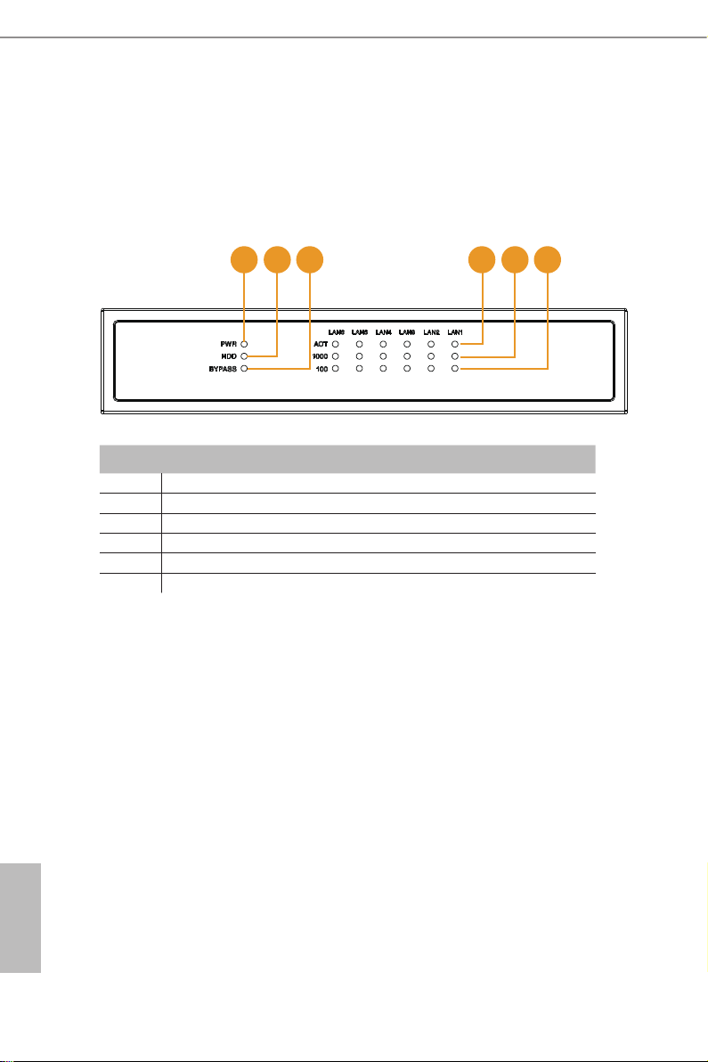
2.1 Front View
1 2 3 4 5 6
No. Description
1 Power Status LED
2 HDD Status LED
3 Bypass Status LED
4 LAN Activity/Link LED
5 100M bps Connection Speed LED
6 1Gbps Connection Speed LED
NAS-9601
4 5
English
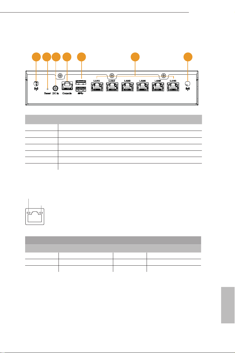
2.2 Rear View
1 2 3 4 5 6 7
No. Description
1Antenna (Optional)
2Reset
3DC-In
4 Console Output (RJ45 (No LED) COM port)
5 USB 3.0 (Type A)
6 Ethernet RJ-45
7Antenna (Optional)
* ere are two LEDs on the LAN port. Please refer to the table below for the LAN port LED indications.
Activity / Link LED Speed LED
Status Description Status Description
O No Link O 10Mbps connection
Blinking Data Activity Orange 100Mbps connection
On Link Green 1Gbps connection
ACT/LINK LED
SPEED LED
LAN Port
6 7
English
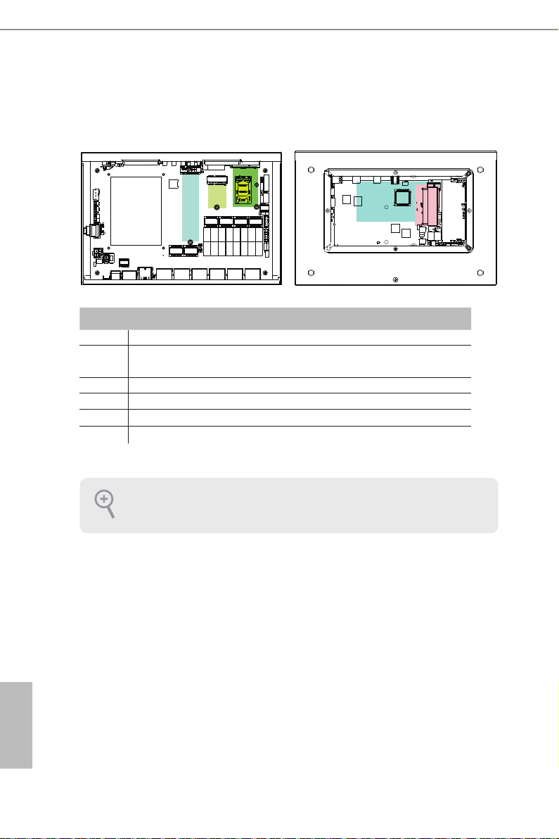
2.3 Inside View
No. Description
1 M.2 Slot (Key M), supports type 2242/2280 M.2 for SATA only
2 M.2 Slot (Key E), supports type 2230 for WiFi + BT Module
(BT function shares from internal USB)
3 Mini PCIe Slot (full/half size, supports PCIex1 and USB device)
4 Sim Socket for WiFi/3G/LTE
5 SO-DIMM Slot, Single Channel DDR3L up to 1600 MHz, Max. 8GB
6 Hard disk drive tray (compatible with 2.5" SATA HDD)
SO-DIMM memory, hard drive, mini-PCIE card, M.2 card and SIM card are not included
with this system.
2
1
3
45
6
Top Bottom

NAS-9601
6 7
English
Chapter 3 Hardware Installation
is chapter helps you install or remove important components.
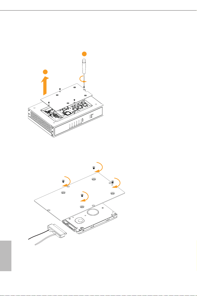
3.1 How to Remove the Top Case
1. Remove the three screws on the top case.
2. en li up and remove the top panel..
3.2 How to Remove the Bottom Case
3. Remove the four screws on the bottom case.
4. en li up and remove the bottom panel..
2
1
2
1

8 9
English
3.3 How to Install the Mini PCIe Card
1. Locate the Mini PCIe slot on the motherboard.
2. Carefully insert the Mini PCIe card into the slot.
3. Tighten the screw to secure the PCIe card to the motherboard.

NAS-9601
8 9
English
3.4 How to Install the Wi Module
1. Locate the M.2 Slot (Key E) on the motherboard.
Insert the WiFi Module Card into the
M.2 Slot for WiFi + BT Module.
2. Tighten the screw to secure the WiFi Module Card to the motherboard.
3. Attach the SMA Wi-Fi Antenna Cables to the WiFi Module.

10 11
English
3.5 How to Install the M.2_SSD Module
1. Prepare a M.2_SSD module and the screw.
2. Depending on the PCB t y pe and length of your M.2 _ SSD modu le, find the
corresponding nut location to be used.
3.Move the stando based on the module type and length.
Note: Supports type 2242/2280 M.2 for SATA only.
No. 1 2
Nut Location CT33 CT32
PCB Length 4.2cm 8cm
Module Type Type 2242 Ty pe 2280
CT32 CT33
1
2
CT33CT32

NAS-9601
10 11
English
4. Peel o the yellow protective lm on the nut to be used. Hand tighten the stando into
the desired nut location on the motherboard.
5. Align and gently insert the M.2 SSD module into the M.2 slot (Key M). Please be aware
that the M.2 SSD module only ts in one orientation.
6. Tighten the screw with a screwdriver to secure the module into place. Please do not
overtighten the screw as this might damage the module.
CT32 CT33
CT1CT2
NUT1NUT2
12 13
English
3.6 How to Install the 2.5-inch Hard Drive
1. Remove the four screws on the bottom case. en li up and remove the bottom panel.
2. Attach the HDD to the bottom panel and secure it using the four screws.
en connect the SATA cable to the HDD.
2
1

NAS-9601
12 13
English
3. en reinstall the bottom panel.
2
1
14 15
English
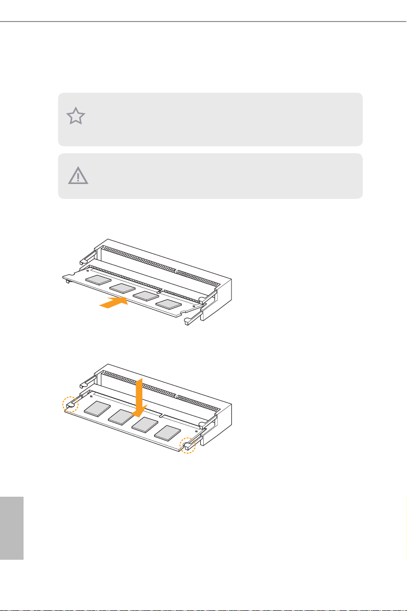
3.7 How to Install the Memory Modules
(DDR3 Low Voltage (1.35V))
1. Carefully insert the SO-DIMM memory modules into the slot at a 30-degree angle.
2. Push down until the modules snap into place.
1. e NAS-9601 requires DDR3L SO-DIMM (1.35V).
2. For dual channel conguration, you always need to install identical (the same brand,
speed, size and chip-type) DDR3L SO-DIMM pairs.
e SO-DIMM only ts in one correct orientation. It will cause permanent damage to the
motherboard and the DIMM if you force the DIMM into the slot at incorrect orientation.

NAS-9601
14 15
English
USB Power On Function:
USB Power On Function allows system power on via USB keyboard/mouse.
is function is useful when the NAS-9601 is mounted behind your display/TV.
To enable USB Power On Function:
1. Enter BIOS by pressing <F2> or <Del> during device startup.
2. Select “Advanced > ACPI Conguration” from the menu.
3. Set “USB Keyboard Power On” and “ USB Mouse Power On” settings to “Enabled”.
4. Press F10 to Save and Exit.

16 17
English
Chapter 4 Software and Utilities Operation
4.1 Installing Drivers
e Support CD that comes with the motherboard contains necessary drivers and
useful utilities that enhance the motherboard’s features.
Running The Support CD
To begin using the support CD, insert the CD into your CD-ROM drive. e CD
automatically displays the Main Menu if “AUTORUN” is enabled in your computer.
If the Main Menu does not appear automatically, locate and double click on the le
“ASRSETUP.EXE” in the Support CD to display the menu.
Drivers Menu
e drivers compatible to your system will be auto-detected and listed on the
support CD driver page. Please click Install All or follow the order from top to
bottom to install those required drivers. erefore, the drivers you install can work
properly.
Utilities Menu
e Utilities Menu shows the application soware that the motherboard supports.
Click on a specic item then follow the installation wizard to install it.
To improve Windows 7 compatibility, please download and install the following hot x
provided by Microso.
“KB2720599”: http://support.microso.com/kb/2720599/en-us
Table of contents
Popular Industrial PC manuals by other brands

Siemens
Siemens Simatic IPC647C operating instructions

IEI Technology
IEI Technology HYPER-KBN Quick installation guide

Siemens
Siemens SIMATIC IPC477E operating instructions

DFI
DFI EC900-FS6 installation guide

Siemens
Siemens Simatic box pc 627b operating instructions

Allen-Bradley
Allen-Bradley H Series user manual


IPCOMM
IPCOMM IPC191I7 General Operating, Maintenance, and Installation Manual

Logic Controls
Logic Controls LC8000 Series Technical specifications

Pro-face
Pro-face PS-3650A Series user manual

Global American Inc.
Global American Inc. 2801030 user manual

Rockwell Automation
Rockwell Automation Allen-Bradley VersaView 6300B user manual

Quanmax
Quanmax KPC-1560 user guide