Mediastar 783 User manual
MediaStar 783 DVB Lan-Caster Unit
200-2342_v2
QUICK START GUIDE
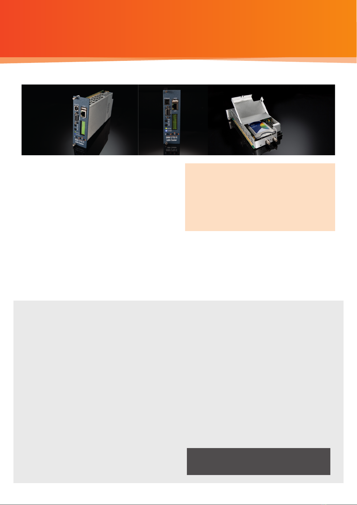
The MediaStar Evolution 783 LAN-Caster allows
DVB-T/C TV and Radio channels to be streamed onto
an IP network. Connect a DVB-T/T2 aerial signal into
the LAN-Caster and use the simple browser based
control interface to stream up to 15 channels from
a single RF multiplex onto the network.
A networked MediaStar Digital Media Decoder display
unit can then decode these streams and output the
video and audio to an LCD or OLED display.
The MediaStar ‘Viewer’ software application can decode
the streams and provide live TV pictures and sound on
a PC.
Important Safety Instructions
1. Read these instructions.
2. Keep these instructions.
3. Heed all warnings.
4. Follow all instructions.
5. Do not use this apparatus near water.
6. Clean only with a dry cloth.
7. Do not block any ventilation openings. Install in accordance
with the manufacturer’s instructions.
8. Do not install near any heat sources such as radiators, heat
registers, stoves or other apparatus (including ampliers)
that produce heat.
9. This unit must be installed using a mains (AC supply) plug and
socket that contains a protective earth (ground).
The mains socket must be located near the equipment,
remain operable and be easily accessible to disconnect the
unit in the case of an emergency.
10. Do not defeat the safety purpose of the polarised or
grounding-type plug. A polarised plug has two blades with
one wider than the other. A grounding type plug has two
blades and a third grounding prong.
The wide blade or the third prong are provided for your safety.
If the provided plug does not t into your outlet, consult an
electrician for replacement of the obsolete outlet.
11. Protect the power cord from being walked on or pinched
particularly at plugs, convenience receptacles, and the point
where they exit from the apparatus.
12.
Only use attachments/accessories specied by the manufacturer.
13. Use only with the cart, stand tripod, bracket, or table specied
by the manufacturer, or sold with the apparatus. When a cart
is used, use caution when moving the cart/apparatus
combination to avoid injury from tip-over.
14. Unplug this apparatus during lightning storms or when
unused for long periods of time.
15. Refer all servicing to qualied service personnel. Servicing is
required when the apparatus has been damaged in any way,
such as power-supply cord or plug is damaged, liquid has
been spilled or objects have fallen into the apparatus, the
apparatus has been exposed to rain or moisture, does not
operate normally, or has been dropped.
The MediaStar range of DVB LAN-Caster
Gateways are a powerful and ultra reliable,
solid state ‘out of the box’ solution for Digital
Terrestrial and CATV reception. When used
with Mediastar DVB-S satellite LAN-Casters and
MPEG encoders, this solution will meet your
entire IP Television Headend and Digital Media
encoding and distribution requirements.
What’s in the box:
•783 DVB-T/T2/C blade
•CAT5 patch cable
•F male to F male loop-through cable
WARNING: THERE ARE NO USER SERVICEABLE
PARTS WITHIN A MEDIASTAR 783 UNIT.
1/12

MediaStar 782-DS Digital Media Player
Installation
This LAN-Caster unit should only be used in a MediaStar Evolution 770 rack that has been fully installed in accordance
with its safety instructions. Refer to the ‘Connecting Terrestrial RF’ section for recommendations of the antenna
Lightening protection required for this equipment. There are no user serviceable parts within this module. Refer all
servicing to qualied service personnel.
The 783 LAN-Caster module may be installed in the 770 rack with the power on or o. If the rack is powered, take
care to ensure this module is engaged correctly in the plastic card guides and does not touch adjacent cards as it is
slid into (or pulled out of) the rack. If the 770 rack is powered down to install a new module, please remember that
all video/audio services being provided by the equipment in that rack will be lost while it is powered o. Electrical
static discharge precautions should be taken when handling the module. If you wish to use a CAM module with the
LAN-Caster, this should be installed inside the module before it is inserted in the rack. Please see the CAM installation
instructions later in this guide for further details.
Quick Start Guide
783 DVB Lan-Caster Unit
200-2342_v2
2/12
To install the 783 module, do the following:
1. Remove the existing front panel blanking plate(s) on
the770 rack. This is done by unscrewing the nger-screw
fasteners. Retain this blanking plate in case the LAN-
Caster module is removed from the rack in the future.
2. Carefully locate the top and bottom edges of the blade’s
printed circuit board (PCB) into the plastic rack slides, and
gently push it in. As the ‘blade’ reaches the back of the
rack, a plastic aperture cover on the rear of the rack will
be pushed o by the module’s connectors. Collect the
discarded aperture cover and dispose of it correctly.
If the rack is powered up, the new module will automat-
ically power up as it is pushed in and the BLUE POWER
LED on the front of the LAN-Caster will be on. The LCD
panel will show the boot up progress of the unit, then
its operational status.
3. Tighten the top and bottom nger screw fasteners to
hold the module in the rack
4. Connect the RF input cable to the rear of the
LAN-Caster in accordance with the instructions below.
5. Set the unit’s IP address, in accordance with the
instructions shown below. Only use IP address details
that have been supplied by your network administrator.
6. Plug the LAN-Caster into the LAN switch using the CAT5
patch cable supplied. It will Auto-negotiate a 100Mbps
link with your network switch.
7. Connect to the LAN-Caster’s conguration web pages
using a PC and Web browser software (e.g. Internet
Explorer, Chrome or Firefox), by entering the LAN-Caster’s
IP address into the browser’s address bar. The LAN-Cast-
er’s specication page will then be shown.
8. Click on the Installation page link on the left hand side
panel, and select appropriate DVB Mode – DVB-T or
DVB-C. Once selected you can click on the Channel Setup
page and click the SCAN button. This will initiate an RF
frequency scan with a progress bar showing the scan
progress. When the scan is complete, a list of detected
RF multiplexes will be shown.
9. Click on the RF multiplex ‘radio’ button to show a list
of the TV and Radio channels that are available from a
particular multiplex at the bottom of the web page. Select
the channels to stream on the network, by ticking the
‘Enabled’ tick-box and entering the stream details into
the webpage. Upto 15 channels may be simultaneously
transmitted, each on its own multicast or unicast address.
Press the APPLY button at the bottom of the page to save
these settings and start the stream transmission on the
network. The channel stream parameters include the
multicast (or unicast) stream address, portnumber, TTL,
and the Dierentiated Services Code Point (DSCP for QoS
packet tagging). Consult your network administrator to
get suitable values for these settings.
Channel settings may be stored for more than one RF
multiplex at a time, but only the channels on the currently
TUNED multiplex will be streamed on the network. The
rotating ‘Tuned’ icon on the list of multiplexes shows
which multiplex is currently ‘Tuned’. When a non ‘Tuned’
multiplex is selected, a tick-box will appear at the bottom
of the webpage to allow this RF multiplex to be ‘Tuned’.
If you don’t know the RF multiplex that contains your
desired TV channel, click on the Channel List link on the left
hand side and click on the letter of the channel name you
wish to stream. An alphabetical list of the channels starting
with the specied rst letter will be shown. Click on the
name of the channel you wish to stream – this will then take
you back to the Channel Setup page with the appropriate
RF multiplex selected. Scroll to the bottom of the page to
see all the channels available from that multiplex.
10.
In ‘normal’ operation when the RF feed is present and the
LAN-Caster is streaming onto the network, the STATUS LED
on the front panel will be constant GREEN. If the RF feed is
missing or the streams have been turned o, the STATUS
LED will ash GREEN. The LCD will show the‘normal’
operating status or the highest priority error condition.
During boot, the STATUS LED will ash ORANGE. If the
STATUS LED is ashing RED, a softwareupgrade is in
progress, and if the STATUS LED shows constant RED,
and internal error has occurred and the unit should be
returned to Cabletime for repair.
MediaStar 782-DS Digital Media Player
Quick Start Guide
783 DVB Lan-Caster Unit
200-2342_v2
3/12
Connecting Terrestrial RF
Connection of the MediaStar 783 LAN-Caster directly or indirectly to a roof top antenna without suitable protection
devices can leave the unit vulnerable to lightning strike/ atmospheric electrical discharge that may result in damage
and void the manufacturer’s warranty.
To minimise the possibility of damage from atmospheric electricity always: -
Follow best practice as dictated by your local electrical code and/or trade association.
•Use coaxial over voltage protection units.
•Bond all masts and antennas to the building protective earth and where available, the lightening protection system.
• Ensure that the screensd of all coaxial cables entering and leaving the headend and/or ampliers are bonded to the
protective earth.
• Unplug this apparatus during lightning storms or when unused for long periods of time
Connect your RF source into the RF IN F-connector on the rear of the unit, and ensure it is tightened up. The RF OUT
F-connector outputs the received signals so the RF can be looped through and passed on to other 783 units.
For terrestrial RF, the RF OUT F -connector outputs the received signals so the RF can be looped through and passed
on to other 783 units.
For Cable TV, it recommended that RF loop through is not used, and that a separate Cable TV feed is provided for each
DVB-C unit using external splitters.
Note: Reliance upon the MediaStar 770 rack safety earth provided by the AC power cord alone is insucient to
protect the unit from atmospheric voltage discharges.
Conguring the LAN-Caster’s IP Address
A suitable IP address should be selected before connection to a network. The LAN-Caster unit is precongured with
a static IP address of 191.53.51.209. This will need to be recongured if it is not suitable for your network.
Use the front panel LCD and push buttons to set the IP address settings.
Press the front panel < (LEFT) and > (RIGHT) buttons to move through the LCD menu options.
Press the OK button to select a menu or conrm a change. Press the < (LEFT) and > (RIGHT) buttons
together to move back up a menu level.
1. Press the < (LEFT) to show the IP Settings menu and press OK to enter the menu.
2. Press < (LEFT) and OK to select the static IP address settings.
3. Press OK to edit the current static IP address; Use the < (LEFT) and > (RIGHT) buttons to select
the appropriate digit and press OK to conrm it. The next digit can then be edited in the same
way. Once the last digit is entered, the IP address is checked and then applied.
4. The IP netmask, gateway and DNS server can be set in the same way.
Note: The MAC address of the unit can be found under the Unit Details/MAC Address menu,
or on the label on the bottom face of the unit.
DVB-T/T2 RF Multiplex Organisation
An ‘RF Multiplex’ is a group of digital TV and radio stations that are ‘grouped’ together and transmitted ‘over the air’
to viewer’s TV aerials at one particular RF frequency. The UK has 6 RF Multiplexes with approximately 120 TV/radio
channels that are transmitted at dierent frequencies in each geographical area of the UK. Other countries use the
same DVB-T/T2 transmission scheme but have their own combination of channels and RF multiplexes. Much the same
applies for Cable TV and radio channels, except that these stations are ‘grouped together’ and transmitted over cable.
The LAN-Caster is able to scan all the signals coming
from the Aerial, and automatically detect the DVB-T/T2
RF multiplexes that it can ‘see’. When it detects a mul-
tiplex, it determines the TV and radio stations that are
available and shows them on the channel setup menu.
Some TV/radio services are encrypted to prevent
un-authorised viewing/listening. These are shown in
the Channel Setup menu with a ‘padlock’ symbol ( ).
This stream can be passed onto the network, but IPTV
decoders or PC software will have to decrypt the
stream before it can be viewed. The LAN-Caster can
be tted with a plug-in CAM module to de-crypt the
streams before launching them on the network.
A single LAN-Caster unit can select ONE RF multiplex,
then extract up to 15 TV or radio services that the user
chooses from that multiplex and stream them onto the
IP network. If a user wants to see more than 15 TV or ra-
dio services from a single multiplex, another LAN-Caster
unit will be required. If a user wants to simultaneously
access TV channels from two dierent RF multiplexes,
then they require two LAN-Caster modules.
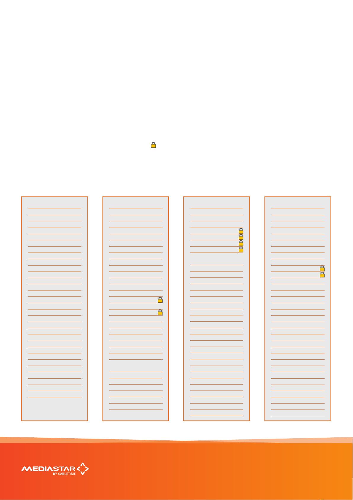
At the time of writing, the UK RF multiplexes contain
the following channels (the channel numbers and
names are shown): For Cable TV, the multiplexes
available are dependent on the services provided by
the cable provider.
MediaStar 782-DS Digital Media Player
Quick Start Guide
783 DVB Lan-Caster Unit
200-2342_v2
4/12
PSB3/BBC B (DVB-T2)
50 BBC One HD
51 ITV1 HD
52 Channel 4 HD
54 BBC HD
117The Space
304301 HD
PSB1/BBC A (DVB-T)
1 BBC ONE
2 BBC TWO
7 BBC THREE
9 BBC FOUR
70 CBBC Channel
71 CBeebies
80 BBC NEWS
81 BBC Parliament
105BBC Red Button
301301
302302
700BBC Radio 1
701BBC R1X
702BBC Radio 2
703BBC Radio 3
704BBC Radio 4
705BBC R5L
706BBC R5SX
707BBC 6 Music
708BBC Radio 4 Ex
709BBC Asian Net.
710BBC World Sv.
193193
723talkSPORT
COM6/ARQ B (DVB-T)
12 Yesterday
15 Film4
18 4Music
21 VIVA
22 Ideal World
24 ITV4
32 Big Deal
35 QVC Beauty
40 Rocks & Co 1
41 Sky Sports 1
42 Sky Sports 2
47 4seven
85 Russia Today
89 Al Jazeera Eng
93 ADULT smileTV2
95 ADULT Babestn
100ADULT Section
110VISION
111CCTV
112Sports
116Racing UK
306Channel Zero
711The Hits Radio
712Smash Hits!
713Kiss
714heat
715Magic
716 Q
718SMOOTH RADIO
722Kerrang!
725Premier Radio
106Mail Travel TV
113CONNECT 1
114CONNECT 2
115CONNECT 3
194194
307TOPUP Anytime1
309TOPUP Anytime3
310TOPUP Anytime5
311TOPUP
Anytime6
724Capital FM
727Absolute Radio
728Heart
COM 5/ARQ A (DVB-T)
11 Pick TV
19 Dave
20 Really
25 Dave ja vu
29 E4+1
36 Create & Craft
37 price-drop
43 Gems TV
46 Challenge
49 Food Network
62 TV Stars
82 Sky News
87 COMMUNITY
90 TV News
94 ADULT smileTV3
96 ADULT PARTY
97 ADULT Blue
98 ADULT Babestn2
108Sky Text
PSB2/D3&D4 (DVB-T)
3 ITV1
4 Channel 4
5 Channel 5
6 ITV2
13 Channel 4+1
14 More 4
28 E4
33 ITV1 +1
102Rabbit
103Gay Rabbit
COM4/SDN (DVB-T)
10 ITV3
16 QVC
17 G.O.L.D.
23 bid
26 Home
27 ITV2 +1
30 5*
31 5 USA
34 ESPN
38 QUEST
39 The Zone
44 Channel 5+1
60 The Jewellery
Channel
72 CITV
91 ADULT Section
92 Television X
99 ADULT Playboy
101Teletext Hols
1041-2-1 Dating

Installing a CAM module
The LAN-Caster can be enabled to work with a third party CI CAM module, so it can decrypt the stream before it is
transmitted on the network. A CI CAM module with the appropriate decryption system will be required (Irdeto, Viac-
cess etc.), together with a valid subscription card. It is the responsibility of the user to ensure that they are entitled by
the broadcaster to decrypt the stream and distribute it unprotected across an IP network to multiple viewing devices.
Cabletime takes no responsibility whatsoever for any unauthorised or illegal use of this equipment.
To install the CAM module, do the following:
1. Ensure the LAN-Caster is enabled to use a CAM module. Check the unit’s part number (shown on the LCD and
on the browser Status page) contains a ‘-CAM’ extension. If it doesn’t, it can be upgraded ‘in-situ’ with a software
enablement code. Contact Cabletime with the LAN-Caster’s serial number for more details.
2. Disconnect the front and rear cables from the LAN-Caster module, and carefully remove it from the rack.
Note: If the RF input signal is daisy-chained between modules, downstream LAN-Casters will lose their RF feed
and will stop outputting TV streams.
3. Open the CAM module access lid by gently squeezing the retaining ‘bumps’ in the sides of the lid while lifting
the rear edge.
4. Take care not to touch any of the electronics inside the module – a static electric ‘zap’ could damage the
components and they may be hot!
5. Insert the subscriber viewing card (smart-card) into the CAM module, ensuring it is the right way up.
6. Take the CAM module and insert it (connector rst) into the plastic card guides near the top of the module.
As you press it home, you will notice the ejector button move outwards.
7. Close the access lid, ensuring that the metal tab on the rear edge of the lid is INSIDE the metal wall.
8. Ensure nothing is loose within the module and then carefully re-insert it back into the rack. Ensure the front
panel xing screws are secure then re-connect the cables.
9. Use the front panel buttons and LCD to check that the CAM module and subscriber card has been properly
recognised by the LAN-Caster module.
10. Use a web browser to access the LAN-Caster’s Status page, and check the CAM module is working OK.
Go to the Channel Setup page and select the appropriate RF multiplex.
11. Enable an appropriate encrypted channel with an IP stream address etc., and press Apply. The video, audio
and data within that stream will then be decrypted by the CAM module before it is launched onto the network.
Any un-encrypted channels enabled will stream out normally.
12. If you have enabled more encrypted channels than the CAM can simultaneously decrypt, the extra channels will
automatically be disabled. This will be shown on the Channel Setup page. If this happens, then you must use a
‘Professional’ CAM with a higher channel decryption capacity, and a suitably enabled subscriber viewing card.
13. If you select channels that use a dierent encryption standard to that supported by your CAM, or if your
subscription service does not include a selected channel, the channel will be streamed onto the network,
with the TV channel still encrypted.
MediaStar 782-DS Digital Media Player
Quick Start Guide
783 DVB Lan-Caster Unit
200-2342_v2
5/12

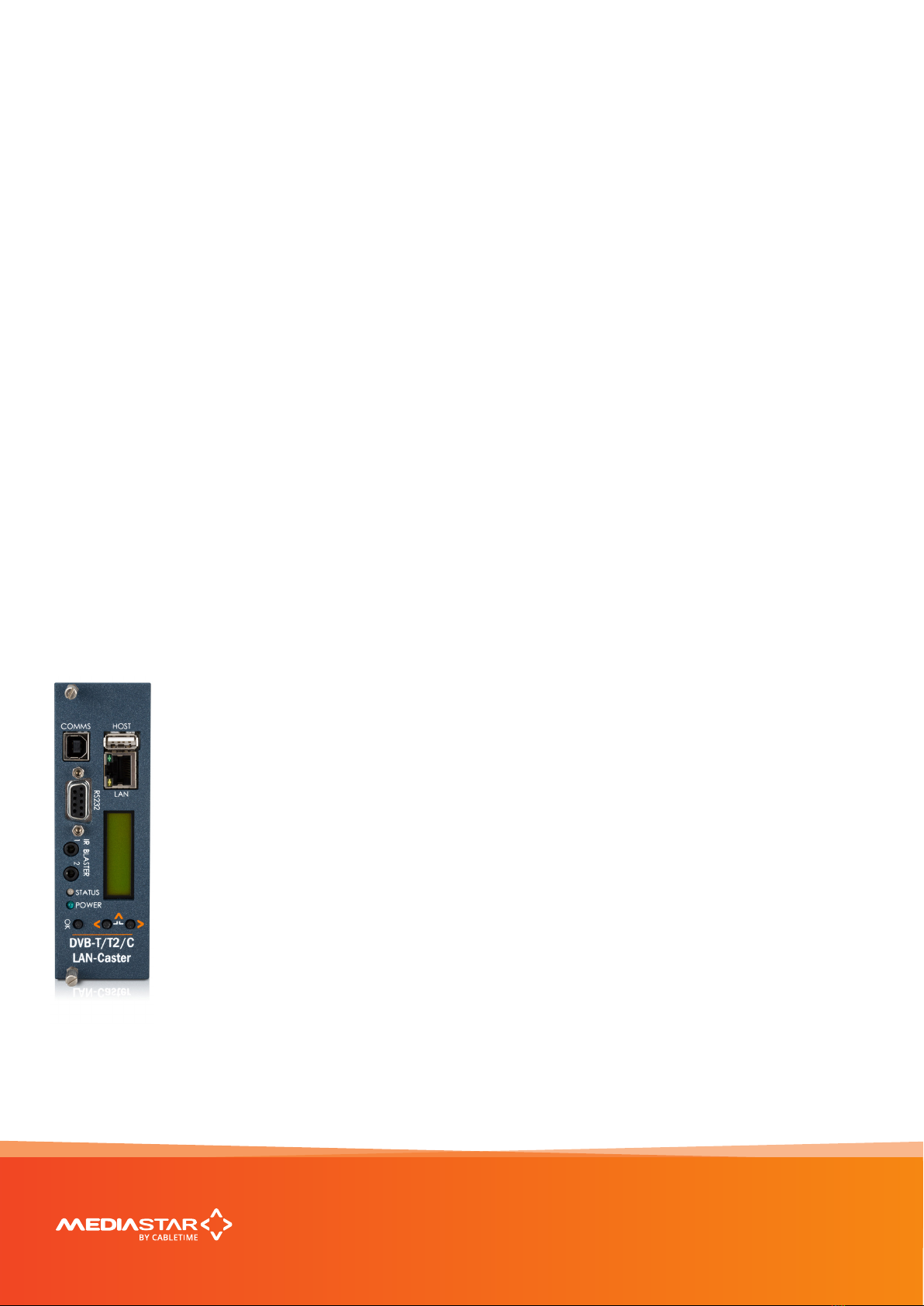
Front panel operation
The front panel LCD can be used with the three adjacent push buttons to view status information and congure the
operation of the unit.
The < (LEFT) and > (RIGHT) buttons scroll up and down
the menus, and change parameter values. The OK
button selects the currently displayed menu item or
conrms a parameter change.
Pressing the < (LEFT) and > (RIGHT) buttons and
releasing them together returns up a menu level,
usually aborting a parameter change.
The upper line of the LCD display (right column)
shows the setting name, and the lower line (left column)
shows the parameter itself and any instructions on how
to change the current setting.
Pressing the < (LEFT) and > (RIGHT) and OK buttons
for 5 seconds and releasing them together will present
a unit RESET option. Pressing the OK button to conrm
will then reboot the encoder.
Front Panel LEDs
Status LED
Green steady: Normal operation
Green pulse: RF input fail or Streams turned o
(see LCD for error condition)
Green/Orange: Unit locator mode on
Orange pulse: Unit booting up
Red steady: Internal error / unit failure
Red pulse: Software upgrade in progress
Power LED
Blue steady: Unit Power on
The structure of the menus presented on the
LCD are as follows:
Part Number and Status
•View unit model number and current operational
status
RF Input status
•View incoming RF details; (Signal level / S//N Ratio /
Mux name / Mux frequency)
Output streams
•View stream details; (Channel No. / Channel name /
Stream address / Port No.)
CAM Status
•CAM present / not present
IP address settings
• DHCP (activate/show allocated address)
• Static IP address (activate/show static IP address)
•View/Edit IP address
•View/Edit Netmask
•View/Edit Gateway address
•View/Edit DNS address
•Network Link
IR Blaster Repeat
• Turn on / o IR Blaster repeat function
Unit details
•MAC address
•Serial number
•Software version number
Locator LED
•Turn on unit locator front panel LED
Help
•Various help topics
MediaStar 782-DS Digital Media Player
Quick Start Guide
783 DVB Lan-Caster Unit
200-2342_v2
6/12

Browser based conguration menus
MediaStar 782-DS Digital Media Player
Quick Start Guide
783 DVB Lan-Caster Unit
200-2342_v2
7/12
The LAN-Caster’s web page conguration menus allow the full range of operational parameters to be set. When using
the web pages, full contextual help is provided on the right side of the screen. When changes have been made, press
the APPLY button at the bottom of the page to ensure these take eect.
Specication
The specication page includes details of the capabilities
of the product. Please note that this unit may not have
all the options mentioned. The Status page shows all
the optional features currently enabled.
Status
Shows the current status of the LAN-Caster, including
the Part number, Device name (used as a DHCP
identier), Serial Number, RF source status, RF Level,
RF S/N Ratio, Received Data Rate, Transmit Data Rate,
Streaming services, Last Scan status, Channels Found,
New Channels Available warning, CAM status, IP
Address, Mac Address, Link Speed, Temperature, Soft-
ware version, Command Set Version, and RS232 status.
Channel Setup
This shows the list of detected RF multiplexes and
the channels in each multiplex. Setup the streamed
channels here.
Channel List
Provides a search facility to nd a channel by its name,
and then takes you to the appropriate RF multiplex on
the Channel Setup page.
Installation
Set-up how the RF scan is performed, the character sets
used for channel names, the network link mode, enable
SAP channel notications and the elementary stream
data types that are transmitted on the network.
RS232 Port
Congure the port settings for the IP to RS232 link or
for the SIPI command interface.
IR Blaster 1/2
These are IR remote control simulators. Press the
buttons on the remote control pictures to generate
IR key presses from the blasters.
IR Blaster Repeat
This allows you to switch on the IR blaster repeat
function. It is useful when locating the IR blaster
module on the receiving equipment.
Network Setup
Allows specication of the Network Connection; Static or
DHCP addressing, device Hostname, IP Address, Subnet
Mask, and Default Gateway settings. Conrm these with
the network administrator before conguring.
Update Locations
Specify the URL of the http server and folder that the
Encoder will look at for software updates and a central
conguration le. The LAN-Caster will only accept new
software that has been produced by Cabletime.
Enablement Code
Enter enablement codes here to recongure or expand
the capabilities of your unit. Details can be obtained
from your reseller or Cabletime.
Set Password
A password may be set to prevent the unauthorised
modication of the LAN-Caster conguration.
A password consists of six digits from 0-9. If the
password gets lost, contact Cabletime for assistance.
SNMP & Syslog
Congure whether to send SNMP or Syslog style ‘event’
warning messages, and set-up the servers to send the
messages to.
Email Logs
Event logs can be periodically emailed to a recipient.
Specify the email server and recipient email address
here.
Event Log
This shows a full list of the ‘events’ that the LAN-Caster
has experienced. These include notications such as
loss of RF lock and telnet connection. Each message
will produce an SNMP or Syslog trap when enabled.
Locator LEDs
Allows the front and rear panel status LEDs to be
ashed ORANGE/GREEN to help identify the physical
encoder unit in a rack.
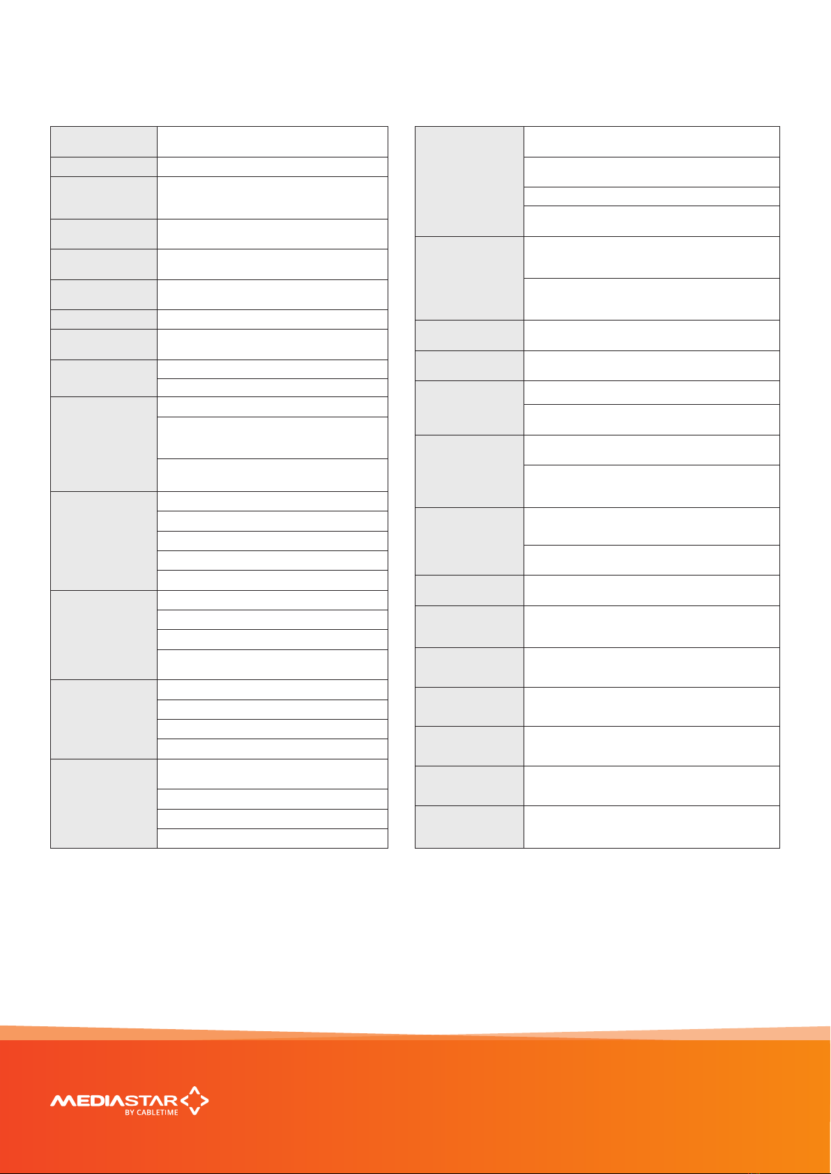
Technical Specications
DIMENSIONS 129 x 41 x 230 mm, occupies 1 (of 9) 770 rack
slot.
WEIGHT 375g
AMBIENT
OPERATING
TEMPERATURE
0º - 40º C, 770 rack ambient
POWER
SUPPLY 7 W (from 770 rack)
LAN RJ45 802.3 10/100 Base-T Auto MDIX Static or
DHCP IP Address. DSCP stream tagging for QoS
NETWORK
PROTOCOLS
UDP, TCP, ARP, DHCP, ICMP, IGMP V2, HTTP,
Telnet, SNMP, Syslog, SAP/SDP, SMTP, DSCP
RF INPUT F type female connector (75 Ohms)
RF FREQUENCY
RANGE 45 to 866 MHz
RF INPUT LEVEL DVB-T/T2: 12 to 95 dBµV (100 KHz RBW)
DVB-C: 28 to 97 dBµV (100 KHz RBW)
RF LOOP-THROUGH
F type female connector (75 Ohms), 0dB gain
Maximum RF input level -70dBm when using
loop-through to connect up to 8 additional
MediaStar DVB-T and T2 LAN-Caster units
RF loopthrough should not be used in DVB-C
installations
DVB-T
DEMODULATION
Modulation: QPSK, 16QAM, 64QAM
Carriers: 2K, 8K
Coding Rate: 1/2, 2/3, 3/4, 5/6, 7/8
Guard Interval: 1/4, 1/8, 1/16, 1/32
FEC: Reed Solomon/Viterbi error correction
DVB-T2
DEMODULATION
Modulation: QPSK, 16QAM, 64QAM, 256QAM
Carriers: 1K, 2K, 4k, 8K, 16K, 32K
Coding Rate: 1/2, 3/5, 2/3, 3/4, 4/5, 5/6
Guard Interval: 1/128, 1/32, 1/16, 19/256, 1/8,
19/128, 1/4 FEC: LDCP, BCH
DVB-C
DEMODULATION
Conforms to ETSI EN 300-429
16QAM, 32QAM, 64QAM, 128QAM, 256QAM
Symbol range: 0.7 - 7.2Msym/s
FEC: RS
OUTPUT STREAMS
15 Multicast or Unicast streams from a single
RF DVB multiplex
Maximum 85 Mbps
Individual TV/radio channels or Entire multiplex
Elementary stream data type ltering
UPGRADABILITY
Enablement code to upgrade from DVB-T to
DVB-T + T2
Enablement code to upgrade from non CAM to
CAM support
Upgrades in-situ, with no hardware change required
Enablement code to upgrade from non DVB-C
to DVB-C support
CAM SUPPORT
CI CAM modules supported with all common
decryption standards (Irdeto, Viaccess, Conax,
Nagravision etc.)
Single and professional multi-channel CAMs
supported PCMCIA connector 5V, 3V CAMs
supported
USB COMMS USB 1.1 Serial Comms device for external
conguration/control
ADMINISTRATION
INTERFACE Web pages served from LAN-Caster
CONTROL
INTERFACE
RS232, USB 1.1 serial interface, or Telnet via IP
Telnet for third part connectivity via TCP control
such as touch panel interfaces
INFRA-RED
BLASTERS
2 o outputs supporting Sky, Sky+, SkyHD IR formats
with web page or remote IP command activation
Remote IP command generates any IR remote control
keypress. 30 - 56 KHz modulated IR waveforms
supported
RS232 PORT
Rx, Tx, CTS, RTS up to 115200 Baud Congured for
SIPI external conguration/control OR
IP to RS232 bi-directional pass through for external
device control
TEMPERATURE
MONITORING
PCB operating temperature available remotely via
web interface
EXTERNAL
IP CONTROL
INTERFACE
ASCII Command/conguration via IP interface,
USB comms and RS232 comms interfaces
ANNOUNCEMENTS SAP (Session Announcement Protocol) notication
of IP streams
EVENT
MONITORING
SNMP or Syslog traps sent to third party SNMP
manager (MIB available on request).
EMAIL
EVENT LOGS
Automatic email of Event log les via external
SMTP server
SOFTWARE Fully upgradable with ONLY protected Cabletime
software from an HTTP server
APPROVALS FCC, CE, CB, TUV Approved
MediaStar 782-DS Digital Media Player
Quick Start Guide
783 DVB Lan-Caster Unit
200-2342_v2
7/12

Notes
MediaStar 782-DS Digital Media Player
Quick Start Guide
9 slot 3RU Chassis with PSU (770)
200-2320 V1
8/12

Notes
MediaStar 782-DS Digital Media Player
Quick Start Guide
9 slot 3RU Chassis with PSU (770)
200-2320 V1
9/12

Declaration of Conformity
Cabletime Limited declares that the products listed below, when installed and
operated as described here, conform to the requirements of the directives shown:
Directives:
2004/108/EC EMC Directive
2006/95/EC Low Voltage Directive
The standards applied are:
EN55022:2006+A1:2007 Information Technology Equipment - Radio Disturbance Characteristics.
EN61000-3-2:2006 Harmonic current emissions.
EN61000-3-3:2008 Voltage uctuations and icker.
EN61000-6-1:2001 Electromagnetic compatibility (EMC) Part 6-1 Immunity.
EN60950-1:2006+A11:2009 Information Technology Equipment. Safety, General requirements.
IEC60950-1:2005 Specication for safety of information technology equipment, including electrical
business equipment, with CB variations for US, Canada, Japan, and Australia.
CB Certication
All EU countries, Switzerland, US, Canada, Australia, New Zealand, Japan, Thailand, Singapore, Brazil, Argentina,
UAE, South Africa, India, Russian Federation, Turkey
I hereby declare that the products listed here conform to the directives shown above when installed and used
according to their respective manuals.
Keith Watts
Technical Director
September 2016
MediaStar 782-DS Digital Media Player
Quick Start Guide
783 DVB Lan-Caster Unit
200-2342_v2
11/12
United States of America
Cabletime Limited declares this equipment has been tested and found to comply with the limits for a Class A
digital device, pursuant to Part 15 of the FCC Rules Subpart B (15.107, 15.109). These limits are designed to provide
reasonable protection against harmful interference when the equipment is operated in a commercial environment.
This equipment generates, uses, and can radiate radio frequency energy and, if not installed and used in accordance
with the instruction manual, may cause harmful interference to radio communications. Operation of this equipment
in a residential area is likely to cause harmful interference in which case the user will be required to correct the
interference at his own expense.
This device complies with part 15 of the FCC Rules.
Operation is subject to the following conditions:
• This device may not cause harmful interference, and
• This device must accept any interference received, including interference that may cause undesired operation.
Correct Disposal of this Product
This marking on the product, accessories or literature, indicates that the product and its electronic
accessories should not be disposed with other household waste at the end of its working life.
To prevent possible harm to the environment or human health from uncontrolled waste disposal,
please separate these items from other types of waste and recycle them responsibly to promote
the sustainable reuse of material resources.
Whilst all reasonable care has been taken to ensure the accuracy of this publication, the publishers and authors
cannot accept responsibility for any errors and omissions. Cabletime Limited reserves the right to revise this
publication and to make changes in the content from time to time without notice.
Copyright © Cabletime 2016. All rights reserved. No part of this guide may be reproduced, stored in a retrieval
system or transmitted in any form or by any means (electronic, mechanical, photocopying, recording or otherwise)
without prior written permission of Cabletime Ltd.
MediaStar 782-DS Digital Media Player
Head Oce
Cabletime Ltd,
64 Greenham Road,
Newbury, Berkshire,
RG14 7HX
United Kingdom
T: +44 1635 35111
www.cabletime.com
USA Oce
Cabletime USA,
100 Valley Road,
Mt. Arlington,
NJ 07856
T: 973 770 8070
Asia Oce
Cabletime Asia
Room 2503, 25/F, Westin Centre
26 Hung To Road
Kwun Tong, Kowloon
Hong Kong
T: +852 3101 2650
Quick Start Guide
783 DVB Lan-Caster Unit
200-2342_v2
12/12
Table of contents
Other Mediastar Gateway manuals

Popular Gateway manuals by other brands

wowvision
wowvision miniVEOS user manual

2N
2N BRI-VoIP-GSM user manual

Lucent Technologies
Lucent Technologies APX 1000 Getting started guide

SMC Networks
SMC Networks FieldServer QuickServer FS-QS-2 F Series Startup guide

Raymarine
Raymarine MICRO-TALK installation instructions

RTA
RTA 460ESDFM-NNA1 Product user guide


