VERAZ NETWORKS I-Gate 4000 PRO User manual

f
ff
fJ
JJ
Jd~íÉ=QMMM=mol
d~íÉ=QMMM=mold~íÉ=QMMM=mol
d~íÉ=QMMM=mol=
==
=
sÉêK=jÉêÅìêó=OKO=
fåëí~ää~íáçå=j~åì~ä
fåëí~ää~íáçå=j~åì~äfåëí~ää~íáçå=j~åì~ä
fåëí~ää~íáçå=j~åì~ä=
==
=

This product is marked with a CE Mark. This mark has been affixed to demonstrate full product
compliance with the following European directives:
(a) Directive 73/23/EEC - Council Directive of 19/02/1973 on the harmonization of the laws of
Member States relating to electrical equipment designed for use within certain voltage limits.
(b) Directive 89/336/EEC - Council Directive of 3/05/1989 on the approximation of laws of the
Member States relating to Electro-Magnetic Compatibility (EMC).
Issue Date: February 6, 1996
This product is marked with a TUV Mark. This mark has been affixed to demonstrate full product
compliance with UL60950 for US and Canada.
This product is marked with a GS Mark. This mark has been affixed to demonstrate full product
compliance with German Safety Requirements.
CB This product is compliant with IEC60950 with all countries deviations, according to the CB
scheme.

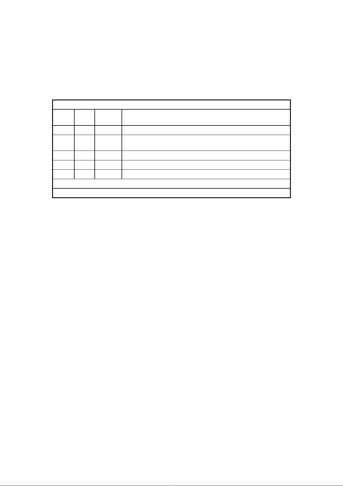
Revision record: I-Gate 4000 PRO Installation
Dwg.
Rev.
Pub.
Rev.
Date Update Description
A0 01 May-03 First edition and printing. Mercury Ver. 1.1. Author: JH
A1 02 Dec-03 Release as Installation-only document. Incorporating changes
relevant to Mercury Ver. 1.2. Author: JH
A2 03 Aug-04 Mercury Ver. 1.3. Auth: MD. Updates: initialization chapter.
A3 04 Apr-05 Mercury Ver. 2.0. Auth: MD.
A4 05 Aug-05 Mercury Ver. 2.2. Auth: MD.
Publication No. 02041802
Dwg. No. 480166-1000-014-95-A4
Copyright by VERAZ NETWORKS INC., 2005. All rights reserved worldwide.
The information contained in this document is proprietary and is subject to all relevant copyright, patent and other
laws protecting intellectual property, as well as any specific agreement protecting VERAZ NETWORKS INC.'s
rights in the aforesaid information. Neither this document nor the information contained herein may be published,
reproduced or disclosed to third parties, in whole or in part, without the express, prior, written permission of VERAZ
NETWORKS INC. In addition, any use of this document or the information contained herein for any purposes other
than those for which it was disclosed is strictly forbidden.
Any representation(s) in this document concerning performance of VERAZ NETWORKS INC.'s product(s) are for
informational purposes only and are not warranties of future performance, either express or implied. VERAZ
NETWORKS INC.'s standard limited warranty, stated in its sales contract or order confirmation form, is the only
warranty offered by VERAZ NETWORKS INC. in relation thereto.
VERAZ NETWORKS INC. reserves the right, without prior notice or liability, to make changes in equipment design
or specifications. This document may contain flaws, inaccuracies, omissions or typesetting errors; no warranty is
granted nor liability assumed in relation thereto, nor responsibilities for third-party rights which may be affected in
any way by the use thereof, unless specifically undertaken in VERAZ NETWORKS INC.'s sales contract or order
confirmation. Information contained herein is periodically updated and changes will be incorporated into
subsequent editions. If you have encountered an error, please notify VERAZ NETWORKS INC.
Direct any comments or questions to Veraz Customer Service at Service@Veraznetworks.com.

This page intentionally left blank.

I-Gate 4000 PRO Installation Contents
02041802-05 Veraz Networks Inc. Proprietary i
Contents
1 Introduction............................................................................................. 1-1
1.1. Purpose of Document ........................................................................ 1-2
1.2. Intended Audience............................................................................. 1-2
1.3. Referenced Documentation ............................................................... 1-2
2 Preparations & Precautions................................................................... 2-1
2.1. Safety Instructions ............................................................................. 2-1
2.2. Power Precautions............................................................................. 2-2
2.3. Battery Instructions ............................................................................ 2-2
2.4. Electrostatic Discharge (ESD) Precautions ........................................ 2-4
2.5. Radio Interference Precautions.......................................................... 2-5
2.6. Tool List............................................................................................. 2-6
3 Planning Installation Site ....................................................................... 3-1
3.1. Physical Specifications ...................................................................... 3-1
3.2. Minimum Distances ........................................................................... 3-5
3.3. Electrical Requirements ..................................................................... 3-6
3.4. Environmental Specifications............................................................. 3-6
3.5. Cooling Requirements ....................................................................... 3-7
4 Unpacking and Inspection ..................................................................... 4-1
4.1. Preliminaries...................................................................................... 4-1
4.2. Chassis.............................................................................................. 4-1
4.3. Cards................................................................................................. 4-3
4.4. Cables and Connectors ..................................................................... 4-3

Contents I-Gate 4000 PRO Installation
ii Veraz Networks Inc. Proprietary 02041802-05
5 Cabinet Installation................................................................................. 5-1
5.1. ETSI Cabinet Installation ................................................................... 5-1
5.1.1. Bolting the ETSI Cabinet to a Concrete Floor ...................... 5-2
5.1.2. Connecting the ETSI Cabinet to a Floating Floor................. 5-4
5.1.3. Connecting the ETSI Cabinet to a Wall ............................... 5-6
5.1.4. Connecting the ETSI Cabinet to an Overhead Cable Run ... 5-8
5.2. 19in./47U high Cabinet Installation..................................................... 5-9
5.2.1. Bolting the 19in./47U high Cabinet to a Concrete Floor ....... 5-9
5.2.2. Connecting the 19in./47U high Cabinet to a Floating Floor 5-11
5.2.3. Mounting the 19in./47U high Cabinets Rack-to-Rack......... 5-13
6 Installing the Chassis............................................................................. 6-1
6.1. Mounting Kit....................................................................................... 6-2
6.2. Attaching the Mounting Brackets to the Chassis ................................ 6-3
6.3. Inserting the Chassis into the Cabinet................................................ 6-4
7 Cooling System (Fan Trays) .................................................................. 7-1
7.1. Fan Operation.................................................................................... 7-2
7.2. Replacing a Fan Tray......................................................................... 7-4
8 Inserting the Cards................................................................................. 8-1
8.1. Card Description and Layout.............................................................. 8-1
8.2. Card Layout Example for E1/DS1 Interface ....................................... 8-6
8.3. Card Layout Example for DS3 Interface............................................. 8-7
8.4. Card Layout Example for STM-1/OC-3 Interface................................ 8-8
8.5. Inserting the Main Cards.................................................................... 8-9
8.6. Inserting the I/O Cards..................................................................... 8-11
9 Connecting the Cables........................................................................... 9-1
9.1. D16I Card (E1/DS1 Trunks)............................................................... 9-2
9.2. D3IO Card ......................................................................................... 9-4
9.3. ST1I Card .......................................................................................... 9-5

I-Gate 4000 PRO Installation Contents
02041802-05 Veraz Networks Inc. Proprietary iii
9.4. TPSI Card.......................................................................................... 9-6
9.4.1. Network Connection ............................................................ 9-7
9.4.2. External Clock Connection .................................................. 9-8
9.5. TPSE Card ........................................................................................ 9-9
9.5.1. Network Connection .......................................................... 9-10
9.5.2. External Clock Connection ................................................ 9-11
9.6. TPSO (Short-haul) Card .................................................................. 9-12
9.6.1. Network Connection .......................................................... 9-13
9.6.2. External Clock Connection ................................................ 9-14
9.7. TPSL (Long-haul) Card.................................................................... 9-15
9.7.1. Network Connection .......................................................... 9-16
9.7.2. External Clock Connection ................................................ 9-17
9.8. ALRM Card...................................................................................... 9-18
9.8.1. Alarm Interface Connection ............................................... 9-19
9.8.2. Monitor Interface Connection............................................. 9-20
9.9. PEFU and PEFD Cards ................................................................... 9-21
10 PDU & Power Connection .................................................................... 10-1
10.1. PDU Installation ............................................................................. 10-2
10.2. Power Connection ......................................................................... 10-3
11 Initialization........................................................................................... 11-1
11.1. Configuring IP Address of TPSM or TPSM-R1 Card ...................... 11-2
11.2. Configuring TPSM/TPSM-R1 Card's Default Router IP Address .... 11-5
11.3. Adding a Terminal to VerazView-xMS............................................ 11-6
11.4. Downloading a Software Version ................................................... 11-6
11.5. Downloading a Configuration Map ................................................. 11-8

Contents I-Gate 4000 PRO Installation
iv Veraz Networks Inc. Proprietary 02041802-05
12 Field Acceptance Testing..................................................................... 12-1
12.1. Prerequisites.................................................................................. 12-1
12.2. Terminal Tests............................................................................... 12-2
12.2.1. Card Presence ................................................................ 12-2
12.2.2. Card Insertion/Removal................................................... 12-5
12.3. Built In Test (BIT)........................................................................... 12-5
12.4. VerazView-xMS Functional Tests .................................................. 12-5
12.4.1. VerazView-xMS SVM ...................................................... 12-6
12.4.2. VerazView-xMS Configurator .......................................... 12-6
12.4.3. VerazView-xMS Status Manager..................................... 12-7
12.5. Transmission Tests........................................................................ 12-7
12.5.1. E1/DS1 Transmission Test.............................................. 12-8
12.5.2. DS3 Transmission Test ................................................... 12-9
12.6. Tone Connectivity Channel Test .................................................. 12-10
12.7. Clear Channel Test...................................................................... 12-10
12.8. Redundant Card Test................................................................... 12-11
12.8.1. TPSM-R1/TPSM Card Redundancy .............................. 12-11
12.8.2. TPSI/TPSx Card Link Redundancy................................ 12-12
12.8.3. DSPK/DSPK-R1 Card Redundancy............................... 12-13
12.8.4. D32M Card Redundancy ............................................... 12-14
12.8.5. PEFU/PEFD Card Redundancy..................................... 12-15
12.9. Field Acceptance Test Results..................................................... 12-16
12.10. Field Activity Certificate.............................................................. 12-16
A PA-41 Test Equipment Setup.................................................................A-1
B Configuration Maps................................................................................B-1
C Glossary ..................................................................................................C-1

I-Gate 4000 PRO Installation Contents
02041802-05 Veraz Networks Inc. Proprietary v
Table of Figures
Figure 3-1: I-Gate 4000 PRO external dimensions.............................................. 3-2
Figure 3-2: Typical cabinet dimensions (with three I-Gate 4000 PRO terminals) . 3-4
Figure 3-3: Two, double Back-to-Back cabinets and separation distance............ 3-5
Figure 4-1: Unpacking the I-Gate 4000 PRO chassis .......................................... 4-2
Figure 5-1: ETSI cabinet base panel ................................................................... 5-3
Figure 5-2: Bolting the ETSI cabinet to a concrete floor ...................................... 5-3
Figure 5-3: ETSI cabinet leveling screws ............................................................ 5-4
Figure 5-4: Bolting the ETSI cabinet to a floating floor......................................... 5-6
Figure 5-5: Connecting the ETSI cabinet to a wall............................................... 5-7
Figure 5-6: Connecting the ETSI cabinet to an overhead cable run..................... 5-8
Figure 5-7: 19in./47U high cabinet mounting dimensions .................................. 5-10
Figure 5-8: Bolting the 19in./47U high cabinet to a concrete floor...................... 5-11
Figure 5-9: Bolting the 19in./47U high cabinet to a floating floor........................ 5-13
Figure 5-10: 19in./47U high Rack-to-Rack ........................................................ 5-14
Figure 6-1: Mounting kit components .................................................................. 6-2
Figure 6-2: Positioning of mounting brackets....................................................... 6-3
Figure 6-3: Inserting a chassis nut ...................................................................... 6-5
Figure 6-4: Inserting the chassis into a cabinet ................................................... 6-5
Figure 7-1: Two Fan Tray units installed in the I-Gate 4000 PRO........................ 7-1
Figure 7-2: I-Gate 4000 PRO single Fan Tray unit .............................................. 7-1
Figure 7-3: Fan Tray's 25-pin D-type connector (rear view)................................. 7-3
Figure 8-1: I-Gate 4000 PRO media gateway shelf ............................................. 8-2
Figure 8-2: E1/DS1 Interface (I/O cards in upper shelf, Main cards in lower shelf)8-6
Figure 8-3: DS3 Interface (I/O cards in upper shelf, Main cards in lower shelf) ... 8-7
Figure 8-4: STM-1/OC-3 Interface (I/O cards in upper shelf, Main cards in lower
shelf) ........................................................................................................ 8-8
Figure 8-5: Removing/inserting a Main card...................................................... 8-10
Figure 8-6: Removing/inserting an I/O card....................................................... 8-11

Contents I-Gate 4000 PRO Installation
vi Veraz Networks Inc. Proprietary 02041802-05
Figure 9-1: D16I card - front panel ...................................................................... 9-2
Figure 9-2: D3IO card - front panel...................................................................... 9-4
Figure 9-3: ST1I card - front panel ...................................................................... 9-5
Figure 9-4: TPSI card's front panel...................................................................... 9-6
Figure 9-5: TPSE front panel............................................................................... 9-9
Figure 9-6: TPSO card's front panel.................................................................. 9-12
Figure 9-7: TPSL card's front panel................................................................... 9-15
Figure 9-8: ALRM card's front panel.................................................................. 9-18
Figure 9-9: PEFU/PEFD cards .......................................................................... 9-21
Figure 10-1: Typical PDU configuration, three-dimensional view....................... 10-1
Figure 10-2: PDU installation ............................................................................ 10-2
Figure 10-3: PEFU/PEFD cards power cable connector.................................... 10-4
Figure 10-4: PDU installation wiring .................................................................. 10-4
Figure 10-5: Typical cabinet power cable connections ...................................... 10-5
Figure 11-1: COM1 Properties dialog box ......................................................... 11-3
Figure 12-1: I/O cards in upper shelf (example of E1/DS1 interface)................. 12-3
Figure 12-2: Main cards in the lower shelf (example of E1/DS1 interface)......... 12-3
Figure 12-3: I/O cards in upper shelf (example of DS3 interface) ...................... 12-4
Figure 12-4: Main cards in the lower shelf (example of DS3 interface).............. 12-4
Figure 12-5: E1/DS1 Transmission test setup ................................................... 12-8
Figure 12-6: DS3 Transmission test setup ........................................................ 12-9
Figure 12-7: Veraz Networks Field Activity Certificate for VoIP products......... 12-17

02041802-05 Veraz Networks Inc. Proprietary 1-1
Introduction
IntroductionIntroduction
Introduction
The I-Gate 4000 PRO is among the industry's first real carrier-class IP Telephony
platforms with carrier-class performance. It is designed to provide all the following
carrier-class features: openness, reliability, scalability, capacity, availability and
fixed line voice quality.
The I-Gate 4000 PRO Media Gateway is divided into two shelves: the lower shelf
containing the Main cards (i.e. Main Hardware section), and the upper shelf
containing the input/output (I/O) interface cards.
The I-Gate 4000 PRO Media Gateway is encased in a 32-slot chassis that complies
with ETSI 300 119 requirements. I-Gate 4000 PRO features front-loading cards and
I/O connections for convenient access to both I/O connections and the cards. There
are no connections at the rear of the terminal. Each interface card has a protective
panel for physical protection and as a guard against electromagnetic interference
(EMI).
Similarly, the Main Hardware section (i.e. lower shelf) provides a door that acts both
as a physical protection and also against electromagnetic interference (EMI). This
feature makes the insertion of blank cards (to occupy empty, unused shelf slots)
unnecessary.
The Main Hardware shelf includes these basic card modules:
! TDM network Interface Cards
! Traffic Handling (Main Cards): Signal processing, switching and packet network
interface cards
! Power feed and alarm cards
Up to three I-Gate 4000 PRO Media Gateway terminals can be installed in a single
cabinet (see Figure 3-2) or up to six I-Gate 4000 PRO Media Gateway terminals in a
back-to-back setup. Other physical characteristics and system specifications are
described in Chapter 3, "Planning Installation Site".
1

Introduction I-Gate 4000 PRO Installation
1-2 Veraz Networks Inc. Proprietary 02041802-05
1.1. Purpose of Document
This manual instructs the technician in the installation of the I-Gate 4000 PRO
system. Included are descriptions of necessary tools, site preparation, media gateway
cabinet installation, insertion of cards and cables, and procedures that bring the I-
Gate 4000 PRO to full operational status. The chapters in this manual are presented
in the order in which the procedures should be carried out. The instructions can also
be used by the customer on-site for re-installation or troubleshooting.
1.2. Intended Audience
This manual is intended for the Veraz technician who is responsible for installing the
I-Gate 4000 PRO system.
1.3. Referenced Documentation
This manual makes references to the following documentation:
! I-Gate 4000 PRO General Description
! I-Gate 4000 PRO Maintenance Manual
! VerazView-xMS Configurator for I-Gate 4000 PRO
! VerazView-xMS Fault and Performance Management for I-Gate 4000 PRO
! VerazView-xMS Administration Guide for I-Gate 4000 PRO

02041802-05 Veraz Networks Inc. Proprietary 2-1
Preparations & Precautions
Preparations & PrecautionsPreparations & Precautions
Preparations & Precautions
This chapter discusses important safety precautions and preparations for installing
your I-Gate 4000 PRO terminal.
2.1. Safety Instructions
The following safety instructions must be observed:
! Restricted Access Area: The DC powered equipment should only be installed in
a Restricted Access Area.
! Installation Codes: The equipment must be installed according to country
national electrical codes. For North America, equipment must be installed in
accordance with US National Electrical Code, Articles 110-16, 110-17 and 110-
18 and the Canadian Electrical Code, Section 12.
! Overcurrent Protection: A readily accessible Listed branch circuit overcurrent
protective device rated 60A for 3 Terminals or 80A for 4 Terminals must be
incorporated in the building wiring.
! Class 1 Laser Product: Refer to the most recent laser standards IEC 60 825-
1:1993 + A1:1997 + A2:2001 and EN 60825-1:1994+A1:1996+ A2:2001.
Caution: This equipment is designed to permit connection between the
earthed conductor of the DC supply circuit and the earthing conductor at the
equipment.
2

Preparations & Precautions I-Gate 4000 PRO Installation
2-2 Veraz Networks Inc. Proprietary 02041802-05
2.2. Power Precautions
! The equipment shall be connected directly to the DC Supply System earthing
electrode conductor.
! All equipment in the immediate vicinity shall be earthed the same way, and shall
not be earthed elsewhere.
! The DC supply system is to be local, i.e. within the same premises as the
equipment.
! There shall be no disconnect device between the earthed circuit conductor of the
DC source (return) and the point of connection of the earthing electrode
conductor.
2.3. Battery Instructions
Warning: There is the danger of explosion if the battery is replaced
incorrectly. Replace the battery only with the same or equivalent type
recommended by the manufacturer. Dispose of used batteries according
to the manufacturer's instructions.
Waarschuwing Er is ontploffingsgevaar als de batterij verkeerd vervangen
wordt. Vervang de batterij slechts met hetzelfde of een
equivalent type dat door de fabrikant aanbevolen is. Gebruikte
batterijen dienen overeenkomstig fabrieksvoorschriften
weggeworpen te worden.
Varoitus Räjähdyksen vaara, jos akku on vaihdettu väärään akkuun.
Käytä vaihtamiseen ainoastaan saman- tai vastaavantyyppistä
akkua, joka on valmistajan suosittelema. Hävitä käytetyt akut
valmistajan ohjeiden mukaan.

I-Gate 4000 PRO Installation Preparations & Precautions
02041802-05 Veraz Networks Inc. Proprietary 2-3
Attention Danger d'explosion si la pile n'est pas remplacée correctement.
Ne la remplacer que par une pile de type semblable ou
équivalent, recommandée par le fabricant. Jeter les piles
usagées conformément aux instructions du fabricant.
Warnung Bei Einsetzen einer falschen Batterie besteht Explosionsgefahr.
Ersetzen Sie die Batterie nur durch den gleichen oder vom
Hersteller empfohlenen Batterietyp. Entsorgen Sie die
benutzten Batterien nach den Anweisungen des Herstellers.
Avvertenza Pericolo di esplosione se la batteria non è installata
correttamente. Sostituire solo con una di tipo uguale o
equivalente, consigliata dal produttore. Eliminare le batterie
usate secondo le istruzioni del produttore.
Advarsel Det kan være fare for eksplosjon hvis batteriet skiftes på feil
måte. Skift kun med samme eller tilsvarende type som er
anbefalt av produsenten. Kasser brukte batterier i henhold til
produsentens instruksjoner.
Aviso Existe perigo de explosão se a bateria for substituída
incorrectamente. Substitua a bateria por uma bateria igual ou
de um tipo equivalente recomendado pelo fabricante. Destrua
as baterias usadas conforme as instruções do fabricante.
¡Advertencia! Existe peligro de explosión si la batería se reemplaza de
manera incorrecta. Reemplazar la batería exclusivamente con
el mismo tipo o el equivalente recomendado por el fabricante.
Desechar las baterías gastadas según las instrucciones del
fabricante.
Varning! Explosionsfara vid felaktigt batteribyte. Ersätt endast batteriet
med samma batterityp som rekommenderas av tillverkaren
eller motsvarande. Följ tillverkarens anvisningar vid kassering
av använda batterier.

Preparations & Precautions I-Gate 4000 PRO Installation
2-4 Veraz Networks Inc. Proprietary 02041802-05
2.4. Electrostatic Discharge (ESD) Precautions
Warning: The I-Gate 4000 PRO terminal contains devices that can be
damaged by accidental introduction of ground or foreign voltages. Therefore,
read carefully all points in this section regarding electrostatic discharge (ESD)
and other electrical precautions before proceeding with installation.
Certain tools and test equipment commonly used on electromechanical systems
should never be used on the I-Gate 4000 PRO. These include: battery buzzers, AC
wire-wrap guns, electric soldering irons and guns, test picks and test lamps.
The following precautions must be observed:
! The I-Gate 4000 PRO uses various Metal Oxide Semiconductor (MOS) devices.
All personal tools, test equipment and metal objects that come into contact with
MOS devices must be electrically grounded. Any static or foreign voltage that is
introduced into these devices may damage them permanently.
! Do not use tools or test equipment, such as test lamps and picks that draw an
appreciable amount of current when attached to the system.
! Do not use tools or test equipment that could introduce foreign voltages into the
system. For example, a battery-powered buzzer operates on only six or nine
volts, but the voltage introduced across the buzzer coil when the magnetic field
collapses can reach a momentary peak in excess of 100V, which can destroy
solid-state devices.
! Use only hand-powered or battery-powered wire-wrap guns in equipment
cabinets. AC-powered wire-wrap guns and lead verification equipment can be
used at the distribution frames only if all cabling has been disconnected from the
cabinet.
! When handling I-Gate 4000 PRO cards, always use an anti-static strap.

I-Gate 4000 PRO Installation Preparations & Precautions
02041802-05 Veraz Networks Inc. Proprietary 2-5
2.5. Radio Interference Precautions
Warning (CE Standard EN 55022): This is a class A product. In a domestic
environment this product may cause radio interference in which case the use
r
may be required to take adequate measures.
Note (FCC Part 15 standard class A): This equipment has been tested and
found to comply with the limits for a Class A digital device, pursuant to Part 15
of the FCC Rules. These limits are designed to provide reasonable protection
against harmful interference when the equipment is operated in a commercial
environment. This equipment generates, uses, and can radiate radio frequenc
y
energy and, if not installed and used in accordance with the instruction manual,
may cause harmful interference to radio communications. Operation of this
equipment in a residential area is likely to cause harmful interference in which
case the user will be required to correct the interference at the user's own
expense.

Preparations & Precautions I-Gate 4000 PRO Installation
2-6 Veraz Networks Inc. Proprietary 02041802-05
2.6. Tool List
Tools normally available at the telephone exchange such as a wrench, pliers,
screwdrivers and wire cutters can be used to install the I-Gate 4000 PRO. In addition
to the above, the following are needed:
! Stepladder for cable routing/
connection over top wiring ducts
and top cabinet fastening
! Pin crimper for grounding wires
! Yardstick or tape measure ! Wire wrap/unwrap tool
! 8 mm and 10 mm drill bits for wood
and concrete
! Lifting device to move the pallet-
mounted containers
! Air pressure spray ! 10 mm drill bit for drilling holes
into the wall
! Medium size (300 g) hammer for
screw anchors
! Hammer drill
! 13 mm socket wrench ! Tool for making Type 43 or
RJ 45 and wire wrap connectors
! Carpenter's level ! 5 mm Allen key
! ¾" open spanner or adjustable
wrench
! Craft knife
! Flat-blade screwdriver with 1/8"
(3.3mm) blade
! Adjustable wrench
! Phillips head screwdriver ! Metal toothed saw
! Crescent wrench ! Metal file
! Pin crimper for D-type 37-pin
connectors
! Jigsaw

02041802-05 Veraz Networks Inc. Proprietary 3-1
Planning Installation Site
Planning Installation SitePlanning Installation Site
Planning Installation Site
Before unpacking elements of the I-Gate 4000 PRO, you need to select a suitable
location for them. Select a site which supports the physical characteristics of the
media gateways, and which conforms to the environmental and power characteristics
of all the elements.
The I-Gate 4000 PRO chassis is designed to be mounted in a cabinet or other rigid
framework that is fixed to the building. A 2.2 meter or 2.6 meter ETSI cabinet or a
19-in./47U high cabinet can accommodate up to three chassis (or up to six if
installed back-to-back), in addition to air buffers and a Power Distribution Unit
(PDU). The I-Gate 4000 PRO can also be installed in other suitable cabinets, such as
NEBS cabinets. Some cabinets contain a network external switch. Refer to Section
3.5 "Cooling Requirements", page 3-7, to arrange for adequate cooling of the system
within the cabinet.
3.1. Physical Specifications
To help you prepare an installation site, Table 3-1 lists the physical specifications
for the I-Gate 4000 PRO terminal (illustrated in Figure 3-1). The ETSI cabinet, other
standard cabinets and the 19 in./47U high cabinet are detailed in Table 3-2, and
Figure 3-2 illustrates these dimensions as a schematic showing three I-Gate 4000
PRO chassis installed in two types of cabinet.
3

Planning Installation Site I-Gate 4000 PRO Installation
3-2 Veraz Networks Inc. Proprietary 02041802-05
Figure 3-1: I-Gate 4000 PRO external dimensions
Table of contents
Other VERAZ NETWORKS Gateway manuals
Popular Gateway manuals by other brands

DEUTSCHMANN AUTOMATION
DEUTSCHMANN AUTOMATION UNIGATE CX-CANopen-(Mapping) - PROFIBUS DP instruction manual

2N
2N VoiceBlue MAX user manual

Essential Trading
Essential Trading DS-1400 installation guide

Helmholz
Helmholz PN/CAN Gateway Layer 2 quick start guide

Arris
Arris Touchstone TG862G/NA user guide

Merak
Merak MMk-736F Quick setup guide