IPAS DaliControl gc16 Service manual

Operating and mounting instructions
DaliControl gc16-2 Order number: 4101-145-21
IPAS GmbH / Rev.1.0
1/4
General use
The IPAS DALI Gateway DaliControl gc16-2 is a device used to control ECGs with a DALI interface (in accordance with EN 62386) via the
KNX installation bus. The device transforms switch and dim commands from the connected KNX system into DALI telegrams and status
information from the DALI bus into KNX telegrams.
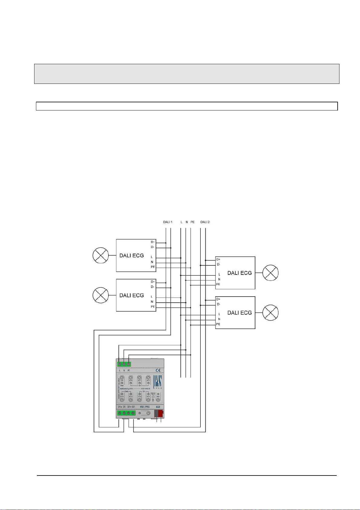
The DaliControl gc16-2 is equipped with two DALI outputs which are independent from one another. 64 ECGs in 16 DALI groups can be
controlled via each output. Both outputs offer the full range of functions described below. The required power supply for the up to 64 con-
nected ECGs comes directly from the device. An additional DALI power supply is not required and not permitted.
The outputs are protected against overload and overvoltage (230V). This applies both to each output as well as overvoltage between
channel 1 and channel 2. The DaliControl gc16 is a so-called category 1 device (according to EN 62386-103). This means the device must
only be used in DALI segments with connected ECGs and not with other DALI control devices within the segment (no multi-master opera-
tion).
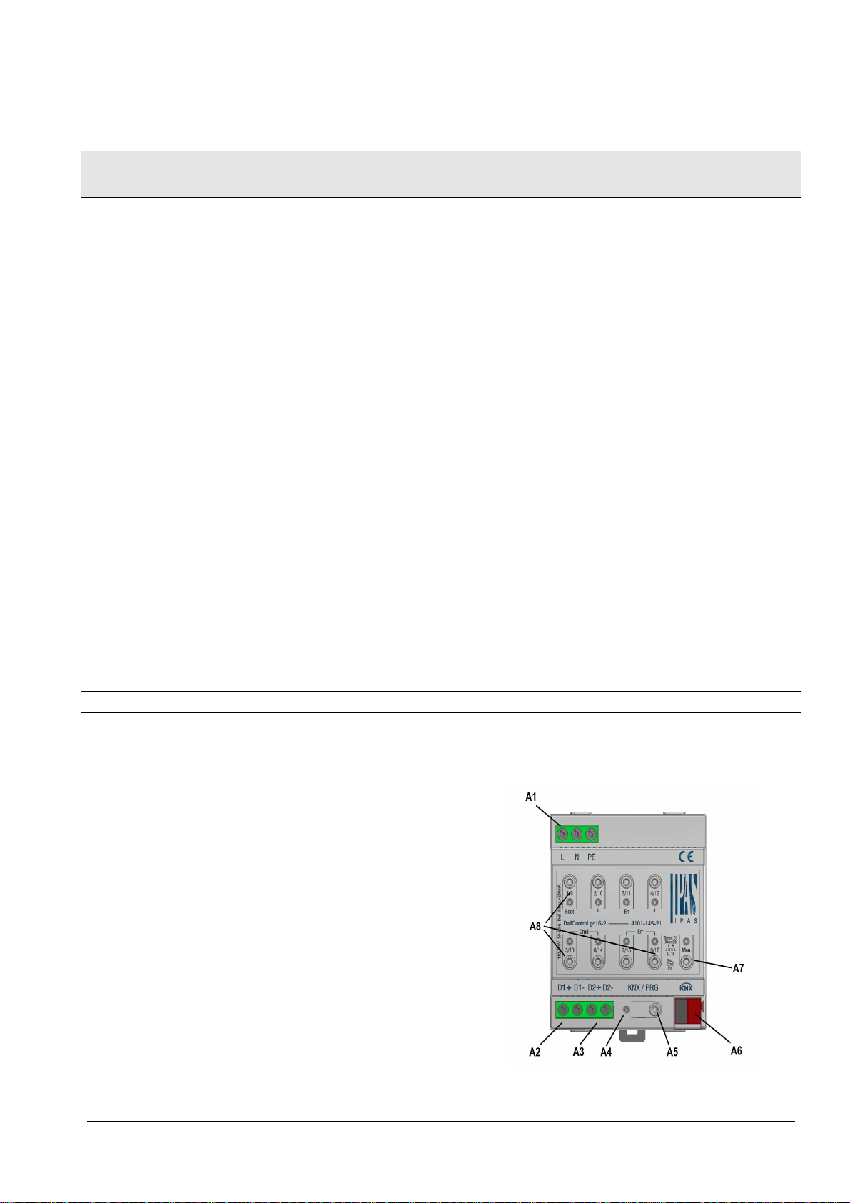
The device comes in a 4TE wide DIN Rail casing so it can be directly integrated into the mains distribution box.
In addition to the pure gateway function, the DaliControl gc16-2 also offers numerous additional functions which are available for each
channel.
•Addressing of up to 16 DALI groups
•Flexible DALI commissioning concept in the ETS5
•Coloured light control with the help of device type 8 ECGs
•Coloured light control depending on ECG sub-type:
Colour temperature(DT-8 Sub-Type Tc)
XY colour (DT-8 Sub-Type XY)
RGB (DT-8 Sub-Type RGBWAF)
HSV (DT-8 Sub-Type RGBWAF)
RGBW (DT-8 Sub-Type RGBWAF)
The DT-8 sub-type PrimaryN is not supported.
•Support of time scheduling programmes to control groups according to values and/or
colour.
•Different operating modes such as permanent mode, night-time mode or staircase
mode
•Integrated operating hours counter for each group with an alarm for when the maxi-
mum life-span has been reached
•Individual fault recognition with objects for each light/ECG
•Complex fault analysis at group/device level with number of faults and fault rate calculation
•Fault threshold monitoring with individually configurable threshold values
•Scene module for extensive scene programming
•“Quick exchange function“ for easy replacement of individual faulty ECGs
•Manual control of group and broadcast telegrams via control buttons on the device (see application program description for operating
instructions)
•Signalling of a fault status via LEDs on the device (see application program description)
DALI devices for individual battery emergency lights of device type DT-1 can be read by DaliControl gc16-2 and switched and controlled
via DALI telegrams. However, DALI commands to start and export test results are not supported. We recommend using the DaliControl
e64 for DT-1 devices.
The special surface for the configuration of DALI segmentes is designed as DCA (Device Control App) for the ETS5.
Please remember to install the corresponding etsapp in addition to the product database knxprod. The etsapp is available for download on
the IPAS website or from Konnex.
Device types and accessories
At present the following DaliControl device types are available:
DaliControl gc16 Order number: 4101-145-11
DaliControl gc16-2 Order number: 4101-145-21
DaliControl e64 Order number: 4101-145-01

Operating and mounting instructions
DaliControl gc16-2 Order number: 4101-145-21
IPAS GmbH / Rev.1.0
2/4
cope of delivery
The following individual components are included in the delivery of the DaliControl gc16-2 device:
•Complete device with connected bus connector
•1x heat shrinkable tubing 1.2 x 2cm for additional insulation of the bus cable
•Operating and mounting instructions
•Delivered in break-proof individual packaging
Application programs
At present the following application programs are available for the DaliControl gc16-2 device:
DaliControl gc16-2-01-0110
For function of the application program see application program description.
Installation advice
•Risk of death by electric shock
•The device is intended for interior installation in dry rooms.
•The device must only be installed and commissioned by an accredited electrical engineer.
•Please follow country-specific safety and accident prevention rules as well as all current KNX guidelines.
•Please follow country-specific rules and regulations for the planning and construction of installations, especially with regard to emergen-
cy lighting systems.
•For the installation, the device must be switched to zero potential.
•Do not open the device! Faulty devices must be returned to the manufacturer.
Technical data
Power supply
•Operating voltage 110 to 240 V, 50 to 60Hz AC or DC
•Maximum power consumption 18W, average power consumption 10W
•Bus power supply via KNX bus line, SELV 24V, ca. 5mA
Connectors
•Mains connector L N PE: Screw connector 3x 1- 2.5mm² single or threaded core
•DALI Bus channel 1 D1+, D1: Screw connector 2x 1-2.5 mm² single or threaded core
•DALI Bus channel 2 D2+, D2- : Screw connector 2x 1-2,5 mm² single or threaded core
•Bus line: Bus connector KNX, screwless 0.6…0.8mm, single core
Control elements
•Programming button to toggle between normal and addressing mode of the KNX
•1 x button Man. to activate manual mode
•8x buttons to toggle between groups in manual mode and to execute broadcast and service functions
•
Display elements
•LED red: Indicates normal/addressing mode
•LED red/green/blue: Indicates manual mode and error message
•8x LED red: Indicates group status and error messages
DALI Bus output channel 1 and channel 2
•Connection of up to 64 ECGs in accordance with EN 62386
•DALI voltage ca. 16 VDC, short circuit proof max. 250mA, basic insulation (no SELV)
•Category-1 device (in accordance with EN 62386-103). No other control devices (DALI-Master) must be used.
•Additional DALI power supply is not required or permitted.

Operating and mounting instructions
DaliControl gc16-2 Order number: 4101-145-21
IPAS GmbH / Rev.1.0
3/4
Mechanical data
•DaliControl gc16-2 casing: Plastic ABS – V0
•Dimensions REG casing 4TE:
Width: 72mm
Height: 55mm
Length: 86mm
•Weight: ca. 200 g
•Mounting: 35mm DIN rail
Electrical safety
•Pollution class: 2
•Protection type (in accordance with EN 60529): IP20
•Protection type (in accordance with IEC 1140) I
•Overvoltage category: III
•KNX bus: SELV DC 24 V
•DALI bus channel 1 and channel 2, each: 16V DC, 250mA basic insulation (no SELV)
EMC requirements
Complies with EN40428, EN61000-6-2 and EN61000-6-3
Environmental conditions
•Weather resistance: EN60721-3-3 class 3k5
•Environmental conditions during operation: -5°C to +45°C
•Storage temperature -25°C bis +70°C
•Rel. humidity (non condensing): 5 % to 93 %
Certification
KNX certified
CE-signage
According to EMC guidelines (residential and commercial buildings), low voltage guidelines
Location and function of display and control elements
The device connectors as well as the programming button and programming LED that are required for KNX commissioning, are only ac-
cessible in the distribution box when the cover is removed.
The buttons required to activate manual control and to operate groups and commands as well as the status and control LEDs are accessi-
ble when the cover is closed.
A1: Mains connection
A2: DALI channel 1 output
A3: DALI channel 2 output
A4: Programming button normal/addressing mode
A5: Programming LED to display normal/addressing mode
A6: KNX bus connector
A7: Operating button/signal LED RGB manual mode
A8: 8x operating button/signal LED red group control/status,
broadcast and service functions
You must always follow the pin assignment as labelled on the casing!

Operating and mounting instructions
DaliControl gc16-2 Order number: 4101-145-21
IPAS GmbH / Rev.1.0
4/4
Mounting and wiring
As an REG device the DaliControl gc16-2 is suitable for mounting in distribution boxes on 35 mm DIN rails. To mount the device it must be
angled to slide onto the DIN rail from above and then locked into place with a downward movement. Please make sure that the security
latch at the bottom side of the device snaps into place and that the device is firmly attached to the rail.
To dismount the device, the security latch can be pulled downwards with a suitable tool and then the device can be removed from the rail.
After the device has been inserted, the cable for the DALI bus should be attached to the upper left connector first. In accordance with EN
62386, the DALI control lines can be carried in a 5-wired cable together with the power supply (simple basic insulation is sufficient). How-
ever, please make sure that these are labelled clearly. For the entire DALI installation of a segment, a maximum cable length of 300m
must not be exceeded. (Recommended cross-sectional area 1.5mm²).
The power supply is connected to the top left-hand side connector in the order indicated on the casing.
To connect the KNX cable, a standard bus connector is plugged into the respective entry on the device. Attention: Please make sure
that there is double basic insulation between the KNX installation and the power supply. To do so, please insulate the wires of
the KNX cable up to the bus connector with the enclosed shrinkable tubing.
Once the connection is complete and the power supply is turned on, you can start commissioning the DALI segment and programming
with ETS5 incl. the necessary etsapp. For all further processes, please see the application program description.
This manual suits for next models
5
Table of contents
Other IPAS Gateway manuals
Popular Gateway manuals by other brands

Notifier
Notifier BACnet GW-3 Installation and operation manual

AudioCodes
AudioCodes Mediant 1000 Hardware installation manual

LeadSolar
LeadSolar Digi installation guide

ZyXEL Communications
ZyXEL Communications eircom D1000 user guide

SI
SI TRO.Y installation instructions

DH electronics
DH electronics DHCON DRC Compact user manual