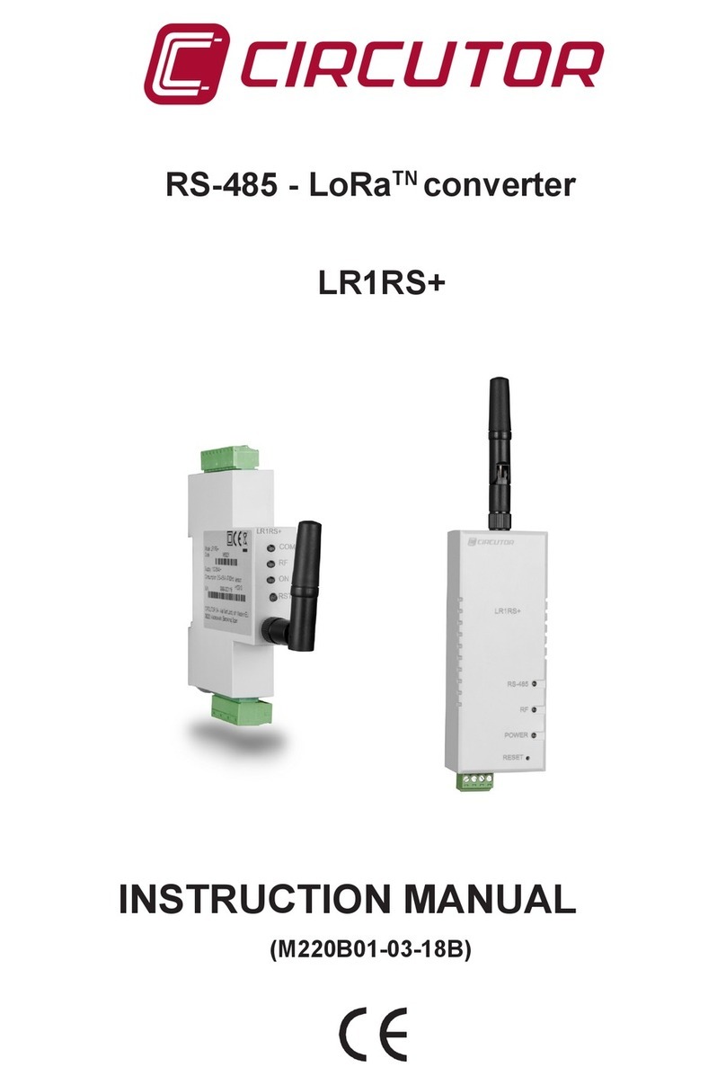
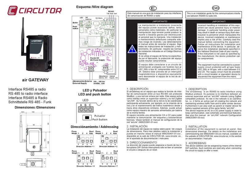
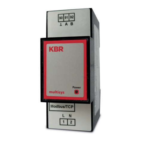
Circutor airLINK User manual

Instructions for the creation of the network
“airLINK”
Application Note
M98253901-03-14A


airLINK network
Application Note 3 of 13
CONTENTS
1GENERAL NETWORK CHARACTERISTICS ....................................................................................................... 5
2BUILDING A NETWORK .................................................................................................................................. 5
3DEVICE ADRESSING ....................................................................................................................................... 6
3.1 GATEWAY ADDRESSING (EXCEPT ETHERNET VERSION) ............................................................................................... 6
3.2 SPEED SETUP ..................................................................................................................................................... 6
3.3 ADDRESSING OTHER DEVICES OF AIRLINK NETWORK. ................................................................................................ 7
4CREATING THE NETWORK.............................................................................................................................. 7
5OPENING AND CLOSING THE NETWORK ........................................................................................................ 8
6GATEWAY LED INDICATORS AND PUSH BUTTON (USB/RS485 VERSIONS)..................................................... 8
6.1 LED BEHAVIOUR AT THE START-UP:........................................................................................................................ 8
6.2 LED INDICATIONS WHEN THE AIRGATEWAY IS NOT ON THE NETWORK:...................................................................... 8
6.3 LED INDICATIONS WHEN THE GATEWAY IS ON THE NETWORK:.................................................................................... 8
7NETWORK CREATION, OPENING , CLOSING AND ADDING NEW DEVICES....................................................... 9
7.1 CREATING A NETWORK ........................................................................................................................................ 9
7.2 OPENING A NETWORK ......................................................................................................................................... 9
7.3 CLOSING A NETWORK .......................................................................................................................................... 9
7.4 JOINING NEW DEVICES TO THE NETWORK ................................................................................................................ 9
7.4.1 Joining end-device type sensors/actuators to the network................................................................... 9
7.4.2 Joining router sensors/actuators to the network .................................................................................. 9
8REMOVING DEVICES FROM THE NETWORK ................................................................................................... 9
9GATHERING SENSOR / ACTUATOR DATA ......................................................................................................10
10 ACCESSING SENSOR/ACTUATOR DATA IN READ MODE ............................................................................10
11 ACCESSING SENSOR/ACTUATOR DATA IN WRITE MODE...........................................................................10
12 BASIC NOTIONS ON THE MODBUS PROTOCOL ..........................................................................................10
13 MAPPING DEVICE DATA ...........................................................................................................................11
14 BASIC NOTIONS ON THE RADIO NETWORK ...............................................................................................11
15 LIMITATIONS IN THE NUMBER OF DEVICES...............................................................................................12
16 NOTES ON THE RADIO COVERAGE OF THE DEVICES ..................................................................................12
17 NOTES ON BUILDING A NETWORK OF DEVICES .........................................................................................12
18 MAINTENANCE AND TECHNICAL SERVICE .................................................................................................13
19 WARRANTY...............................................................................................................................................13

airGATEWAY
4 o 13 Application Note

airLINK network
Application Note 5 of 13
1 GENERAL NETWORK CHARACTERISTICS
The “airLINK” family of devices can be used to create a network of sensors and actuators. Such sensors
and actuators are able to convey their operating data (input values and status, output settings,
parameters, etc.) to a centralizing hub device called Gateway via a wireless network based on radio (RF)
link, using an IEEE 802.15.4 compliant protocol (ZigBee, Miwi compatible).
A two-way communication is established between devices and Gateway. Besides transmitting their
operating status, the devices in the network can receive data and commands. It is possible to access the
data gathered by the Gateway through an USB/485 serial communications link using Modbus-RTU
protocol or through an Ethernet port and Modbus-TCP/IP protocol.
The Gateway is transparent for the purposes of serial communications. Whether it is a PLC or a PC with
supervision software, the client connected to the Gateway can access all the data for each individual
sensor in both read and write modes, individually addressing them as though they were wired.
The sensors/actuators are divided into two groups:
a) End sensors/actuators linked to network but without routing capability. Usually battery-powered.
b) airLINK nodes, linked to network with router functions. Usually powered from mains.(airBRIDGE,
airREPEATER , others, but only one airGATEWAY)
The radio devices in these two groups are fundamentally different. In fact, the routers are responsible for
maintaining the radio network infrastructure and extending the capacity of the Gateway, while the end
devices do not have this capacity.
Coordinator
(Gateway)
Bridge
Repeater
End device
E
E
E
E
E
G
R
R
B
External
supervisor
PC or PLC
N
N
Generic serial
devices
RF link
Serial link
End device
End device
End device
End device
Repeater
Fig. 1-1. Example of network structure
2 BUILDING A NETWORK
The Construction of a new “airLINK” network involves the following steps:
A. Establishing the Gateway address (see paragraph 3)
B. Connecting the Gateway to a control/supervision system and turning it on
C. Creation of the network by the Gateway (see paragraph 4)
D. Opening the network by the Gateway (see paragraphs 5,6)
E. Establishing addresses for new sensor/actuator devices (see paragraph 3)
F. Turning on the new sensor/actuator devices
G. Annexing the new sensor/actuator devices into the network (see paragraph 7)
H. Closing the network by the Gateway (see paragraphs 5,6)
I. Points E, F, G must be repeated for all devices one wishes to include in the network.
If a new device is to be inserted in an existing network, points D, E, F, G, H must be performed.

airGATEWAY
6 o 13 Application Note
3 DEVICE ADRESSING
An essential prerogative of all “airLINK” devices is that each one must have its own unequivocal address.
Each device, except the Router-Bridge and the Repeater devices, have a dip-switch set, which must be
set to the address assigned to the unit. The address must be set before the device is annexed to the
network, since the DIP switches are read only once, when switching the circuit board ON or after a
RESET.
3.1 Gateway Addressing (except Ethernet version)
The connected client (PC or PLC), accedes to the network through the GATEWAY address. This allows
the access to the operating data of the GATEWAY itself and to set and manage the radio network
parameters.
The airGATEWAY address can be set-up by means of a set of 3 DIP switches (1 to 3 in the schematics of
Fig. 3-1). DIP4 is not used for assigning the address but for choosing the speed of the serial port.
Valid Gateway addresses are ranging from 1 to 7. The default configuration is peripheral Nr 1.
Address = 1
1 2 3 4
Weight 1 2 4 Baud
Rate
ON
Address = 2
1 2 3 4
Weight 1 2 4 Baud
Rate
ON
Address = 6
1 2 3 4
Weight 1 2 4 Baud
Rate
ON
Address = 7
1 2 3 4
Weight 1 2 4 Baud
Rate
ON
Fig. 3-1. airGATEWAY DIP switches set
The DIP switches are read only once, when switching the circuit board ON or after a RESET.
A modification of the DIP switches position is only taken into consideration after a RESET. It
is recommended to set the DIP switches before switching the device ON.
Be careful when assigning Gateway address through a remote link. Setting a wrong address
may cause the loss of the link. In this case the client will be unable to communicate again with
it and therefore will be unable to re-configure it via remote.
For all peripherals, in case that the radio link is established through an airBRIDGE, the lower
address allowed is 50 and the maximum is 240.
See also the airGATEWAY instructions manual M98253401-03-xxx
3.2 Speed setup
DIP4 is used to setup the speed of the serial port. (DIP4 : OFF->9600Baud; ON->19200Baud).

airLINK network
Application Note 7 of 13
3.3 Addressing other devices of airLINK network.
Valid sensor/actuator addresses are numbers ranging from 16 to 127. Each of these devices has a 8-
setting dip-switch that uses binary logic: switch “1” corresponds to the least significant bit; the “ON”
position corresponds to a value of 1 (see Fig. 3-2)
Address = 17
1 2 3 4 5 6 7 8
Weight 1 2 4 8 16 32 64 128
ON
Fig. 3-2. Sensor / Actuator DIP switches set
The DIP Switches are read only when switching the circuit board ON. A modification in the
Dipswitch’s position is taken into consideration only after the device has been reset. In order
to reset the device, remove the battery from the device, press the pushbutton so that to make
the residual energy in the circuit run out, and then re-install the battery.
Be careful when assigning the addresses. Two devices with the same address would “pour”
their data into the same GATEWAY register and this would generate ambiguity which would
be difficult to identify in subsequent network operations.
4 CREATING THE NETWORK
Network creation can only be performed by the Gateway. In fact Gateway is used to create the wireless
network to which all devices will be subsequently annexed.
Network creation can only be performed if the Gateway is not already part of a network.
The network creation operation is performed by pressing the push-button on the Gateway or by using the
Modbus protocol to send the Gateway the suitable special command.
After the network creation, the Gateway stores the parameters describing the network in its non volatile
memory, so that, when the Gateway is turned OFF, subsequent operation is not compromised and, when
it is turned ON again, it will resume functioning on the previously formed network.
Creating the network is the first operation to be completed when forming an “airLINK” network and the
airGATEWAY is the only device which can complete this operation.
To create the network it is necessary to determine the parameters that completely describe the network;
they are the channel (ranging from 11 to 26), the PAN ID (ranging from 0 to 32767) and the Extended
PAN ID (number on 8 bytes). (PAN stands for Personal Area Network)
Create the network at the moment of the first installation of the airGATEWAY; the network parameters
found during the process remain indefinitely in the device’s non-volatile memory, as long as the device is
not voluntarily disassociated. This process can be activated only if the device does not already have
network parameters (non-joined device).
There are two ways of creating a network on a Gateway which is not on the network:
a) Activation by pressing the airGATEWAY push button
b) Activation by sending the appropriate command password to airGATEWAY
Activation by pressing the push button causes automatic network creation; this means the airGATEWAY
scans all available channels to find the one with the least interference.
When the most suitable channel has been chosen, the airGATEWAY generates randomly PAN ID and
extended PAN ID parameters (ensuring that there are no other networks with the same value).
After the parameters have been chosen, the network creation takes place.

airGATEWAY
8 o 13 Application Note
Since airGATEWAY is able to find the most suitable channel, it is recommended to create the network
directly in the final installation place.
Instead, when activating by sending the command password, choosing the channel, PAN ID and
extended PAN ID is left to the operator.
This second option is useful when a faulty airGATEWAY needs to be replaced and is performed by
supplying the network parameters which are identical to those which were assigned to the replaced
device. In this way, it is possible to substitute the Gateway without necessarily recreating the entire
network.
Two Gateways should never have the same network parameters when working on the
same network. This would generate confusion, as both devices would share the same
network address and thus it will be impossible for the network to work properly.
For further explanations on network creation by command password refer to the airGATEWAY
instructions manual M98253-03-xxx
5 OPENING AND CLOSING THE NETWORK
The term "open network" indicates a network to which new devices can be annexed. The term "closed
network" indicates that the network cannot accept new devices.
The network made up of airLINK devices is a normally closed network, which can only be opened from
the airGATEWAY.
Network opening and closing operations are performed by pressing the push-button on the airGATEWAY
or by using the Modbus protocol to send the Gateway the suitable command.
6 GATEWAY LED INDICATORS AND PUSH BUTTON (USB/RS485 VERSIONS)
The airGATEWAY has three LED through which it is possible to obtain information on the device's
operating status. Furthermore, the Gateway has a push-button which makes possible to command the
device. The nomenclature of air GATEWAY LED indicators can be seen in Fig. 6-1
Push
button
“A” (external LED ) “B” (central LED)
“C” (right
LED)
Fig. 6-1. airGATEWAY LED
identification
6.1 LED behaviour at the start-up:
After a RESET of the Gateway, all the LED
light for 2
seconds, then all flash fast during another 2 seconds. At the
end of flashing, the device starts the normal operation.
6.2 LED indications when the airGATEWAY is NOT on
the network:
LED “A” is permanently ON , LED “B” and LED “C” are
permanently OFF
6.3 LED indications when the Gateway is on the network:
LED “A”: Shows the Working Status
Slow flashing (1Hz) Closed Gateway
Fast flashing (4Hz) Open Gateway
LED “B” (central LED): Shows the Radio Link status
OFF No Router with good link in the proximity
1 flash + pause One Router with good link in the proximity
2 flashes + pause Two Routers with good link in the proximity
3 flashes + pause Four or more Routers with good link in the proximity

airLINK network
Application Note 9 of 13
LED “C”: Shows the Radio Activity
LED C is most of time OFF, indicating that here is no activity in the radio communications channel,
but it gives a short flash when a radio message is received or transmitted.
7 NETWORK CREATION, OPENING , CLOSING AND ADDING NEW DEVICES
7.1 Creating a network
When the Gateway is not on the network, pressing the push button will start the process of network
creation by turning LED “B” on. Then, if the push button is not pressed again within ten seconds, the
scanning process starts searching the best wireless channel.
This scanning process takes approximately 20 seconds, during which only LED “B” is on.
Once the scanning process has been completed, the Gateway has created a network and LED “B” starts
flashing when transmitting or receiving data.
7.2 Opening a network
When the Gateway is on a network, pressing the push button on the circuit board opens the network (in
this case LED “A” starts flashing).
7.3 Closing a network
When the network is open, pressing the push button, on the Gateway circuit board, closes the network. If
the network is left open, it closes automatically 15 minutes after it has been opened.
7.4 Joining new devices to the network
New devices can be annexed to the network only when the Network is open. Once joining has been
completed, the airGATEWAY stores the parameters describing the network in its non volatile memory so
that, when it is turned off, set-up parameters are not lost and, when it is turned on again, it will resume
functioning on the network it was previously joined to.
The process for join a device to the network differs depending on the type of sensor/actuator involved.
7.4.1 Joining end-device type sensors/actuators to the network
To be joined to the network, end-devices must be stimulated by pressing the push-button on their
circuit boards. The joining process generally takes 20 seconds. Once the process has been
completed, if the device did not find an available network, it reverts to energy-saving stand-by mode
waiting for the push-button to be pressed again.
7.4.2 Joining router sensors/actuators to the network
To be joined to the network, router type devices do not require any particular stimulation. If they are ON
and not in a network, they automatically scan the RF signal in search of an available network. This
scanning phase runs indefinitely until the router device has found an open network.
8 REMOVING DEVICES FROM THE NETWORK
All devices, including the Gateway, are able to run the operation needed to disconnect them from the
network and restore their default status (non joined device). To perform this operation, press the push-
button on the circuit board, within 20s after turning ON the device, and keep it pressed for more than 10s
A disconnected device can be reinserted in the previous network by repeating the annexing process. This
does not hold for the Gateway; if it is disconnected, any subsequent network creation would cause the
device to generate a new network that differs from the previous one. In this case it would be impossible to
reach any of the devices in the previous network..

airGATEWAY
10 o 13 Application Note
9 GATHERING SENSOR / ACTUATOR DATA
All sensor/actuator devices in an “airLINK” network send radio messages to airGATEWAY, with full
description of their status at regular and programmable intervals. In response to this message, the
GATEWAY sends a message indicating the actions to be performed or any variations to be made to their
parameters.
10 ACCESSING SENSOR/ACTUATOR DATA IN READ MODE
The GATEWAY stores the data transmitted by sensors/actuators in its local memory. This information can
be accessed from memory, at any time through the Modbus protocol. When user accesses data of a
specific device, these data do not refer to the instant in which the reading is performed but rather refer to
the last message received from the specific device.
11 ACCESSING SENSOR/ACTUATOR DATA IN WRITE MODE
A change in a sensor/actuator's parameter is initially written in the memory of the Gateway. In the case of
end-device sensor/actuator, the Gateway sends the message containing the new parameter only after it
has received a message from the sensor/actuator itself.
On the other hand, in the case of router sensors/actuators, the Gateway immediately sends out the
message containing the new parameter
12 BASIC NOTIONS ON THE MODBUS PROTOCOL
The data stored in the Gateway can be read and modified using the Modbus-RTU (Remote Terminal Unit)
protocol if it is a USB/RS485-type Gateway, or using the Modbus-TCP/IP protocol if it is an Ethernet-type
Gateway.
In the case of the Modbus-RTU, the communication frame is as follows:
Start
4 bytes End
4 bytes
Address
1 byte Function
1 byte Data
n bytes CRC
2 bytes
Delay Delay
Fig. 12-1. Modbus RTU frame
The format for serial transmission of 1 byte is as follows: 1 start bit ; 8 data bits (LSB first) ; 1 bit for even /
odd parity or no bit for no parity ; 1 stop bit if parity is used or 2 bits if no parity (total 11 bits)
The Modbus specification defines a silent-interval (Pause) of at least 3.5 chars between two frames to
transmit. Within a message two chars may be separated for not more than 1.5 chars. A typical data
transmission looks like:
Pause Frame 1 Pause Frame 2 Pause Frame 3 ...
≥3,5 char≥3,5 char ≥3,5 char
Fig. 12-2. Modbus RTU sequence of frames
The CRC is a 16-bit type and it is calculated, in compliance with the Modbus standard, with the
polynomial X16+X15+X2+1.
In the “airLINK” network, the airGATEWAY implements the following function codes:
01 - READ COIL STATUS
02 - READ INPUT STATUS
03 - READ HOLDING REGISTER
04 - READ INPUT REGISTER
05 - FORCE SINGLE COIL
06 - PRESET SINGLE REGISTER

airLINK network
Application Note 11 of 13
For a more extensive indication of the protocol, see specific Modbus® RTU protocol documentation.
13 MAPPING DEVICE DATA
Each component in the “airLINK” family of devices has a specific data mapping. For a description of this
mapping, see the pertinent documentation for the individual devices.
14 BASIC NOTIONS ON THE RADIO NETWORK
From the radio point of view, the “airLINK” family devices make up a network built on the ZigBee standard
from which it inherits its structure and properties. ZigBee is a proprietary-type network. For this reason the
devices in this network cannot interoperate with other ZigBee devices produced by different
manufacturers.
From the network point of view, it is composed of three different types of nodes:
C Coordinator Node (Gateway)
R Router (Repeater) sensors/actuators
E End-Device sensors/actuators
A correctly built network is composed of a single C-type node and a variable number of R and E-type
nodes. The C (coordinator)-type node has the fundamental task of creating the network. The R (router)-
type nodes are the basic constituents of the network; they play an active role in maintaining and routing
radio traffic from and to other devices in the network.
The prerogative of the C and R-type nodes is that they are always on and have no constraints regarding
power consumption. For this reason the C and R-type nodes are generally powered from the mains.
The E (End-Device)-type nodes do not actively participate in network management; they engage in a
wireless dialogue with the other devices only when this proves necessary to deliver a message (and
possibly to receive a response to the message). For this reason the E-type nodes require less power and
can thus be powered by a battery allowing a reasonable battery life.
To be able to communicate, the E-type nodes must establish an unequivocal link, called relationship, with
a C or R-type node. For this reason, the E-type nodes must be installed in the vicinity of at least one C or
R-type node.
Coordinator
(Gateway)
Bridge
Repeater
End device
E
E
E
E
E
G
R
R
B
External
supervisor
PC or PLC
N
N
Generic serial
devices
RF link
Serial link
End device
End device
End device
End device
Repeater
Fig. 14-1. Example of the topology of an airLINK network

airGATEWAY
12 o 13 Application Note
15 LIMITATIONS IN THE NUMBER OF DEVICES
In its minimal extension, the “airLINK” network is composed of one Gateway and one Router or one End-
device.
To determine the maximum network extension, that is the maximum number of nodes that can be used in
the network, several factors must be taken into consideration:
1) Device addressing space: internal Gateway constraints limit the maximum number of devices internally
mapped to 112 (with addresses ranging from 16 to 127).
2) Maximum Number of End-Devices: The maximum number of end-devices that can, at any one time, be
'children' of a given Router (or Gateway) is 32. Practical questions of safety and redundancy recommend
having at least two possible parent routers for each End-Device installed, and this leads to use of at least
one router every 16 End-Devices.
3) Practical reasons recommend never exceeding the limit of 60 Routers.
16 NOTES ON THE RADIO COVERAGE OF THE DEVICES
The radio coverage of the devices is approximately one hundred meters in the open field, that is, without
the presence of any obstacles. In the closed field, the capacity is significantly reduced and highly variable,
depending on the individual case. Often dividing walls or reinforced floors can prove to be insurmountable
obstacles.
It is not always possible to determine the best position for the devices, particularly the routers, according
to theory; rather it must be determined empirically by trial during the actual installation.
17 NOTES ON BUILDING A NETWORK OF DEVICES
There are some practical rules for correct construction and installation of a network of “airLINK” devices.
1) When possible install the Gateway in a central position respect to the other nodes.
2) The Gateway must be able to communicate with at least two routers.
3) Each router must be able to communicate with at least two other routers.
4) Each router must not be able to communicate with more than sixteen other routers.
5) The number of routers must be calculated according to the number of End- Devices. Arrange at least
one router every 16 End-Devices.
6) Each End-Device must be able to communicate with at least two routers.
7) When possible install all devices in high positions and at a distance from metal masses.
8) When possible install the devices so that they fall within eyesight.
9) Limit the radio traffic as much as possible: experience has taught us that it is advisable to never
exceed an overall maximum number of messages every three seconds. This limit thus becomes the
minimum setting for the transmission frequency parameter for each node and this, in turn, depends on the
number of nodes in the network. If “n” indicates the number of nodes in the network, we recommend that,
for each node, the automatic transmission time must be set greater or equal than “3*n” seconds.

airLINK network
Application Note 13 of 13
18 MAINTENANCE AND TECHNICAL SERVICE
In the event of questions or concerns regarding operation or malfunction of a device, notify to the
Technical Assistance Service (S.A.T.) of CIRCUTOR, SA.
SPAIN 902 449 459
INTERNATIONAL (+34) 93 745 29 00
Technical assistance Post-sales Department
Vial Sant Jordi, s/n –
08232 – Viladecavalls
Barcelona – Spain
e-mail: sat@circutor.es
Web: www.circutor.es
19 WARRANTY
CIRCUTOR warrants its products in case of manufacturing defects for a period of two years from the
delivery of the equipment.
CIRCUTOR will repair or replace defective products returned within the warranty period.
No returns will be accepted nor will repair or replace any equipment if not accompanied by a
report explaining the observed defect or the reason for the return.
The warranty is void if the equipment has been subject to "misuse" or the customer did not follow the
instructions for storage, installation and maintenance contained in this manual. We understand as
"misuse" any use situation contrary to National Code or exceeding the limits given in the section on
technical and environmental characteristics of this manual.
CIRCUTOR declines all responsibility for any damage to equipment or other parts of the facility, caused
by a bad installation or "misuse" of the equipment.
Consequently, this warranty does not apply to faults caused in the following cases:
1. Faults due to over voltages and / or electrical supply disruptions
2. Faults due to water or humidity, if the IP rating of the product is not suitable.
3. Faults due to lack of ventilation and / or excessive temperatures
4. Faults due to improper installation and / or lack of maintenance
5. In case that the equipment has been serviced, repaired or modified without authorization from
CIRCUTOR
Table of contents
Other Circutor Gateway manuals
Popular Gateway manuals by other brands
AudioCodes
AudioCodes Mediant 800 MSBG Cli reference guide
ORiNG
ORiNG IMG-W6121+-4G-M12 user manual
Anywire
Anywire ASLINK B2G78-PB1 user manual
Thermal Solutions
Thermal Solutions ProtoNode FPC-N34 BACnet Startup guide
Shenzhen Hongdian Technologies
Shenzhen Hongdian Technologies A50E quick start guide
D-Link
D-Link DVG-1120M manual
