MEDICAL ILLUMINATION CENTURION EXCEL Manual
INSTALLATION AND SERVICE
MANUAL
THE 21ST CENTURY SERIES
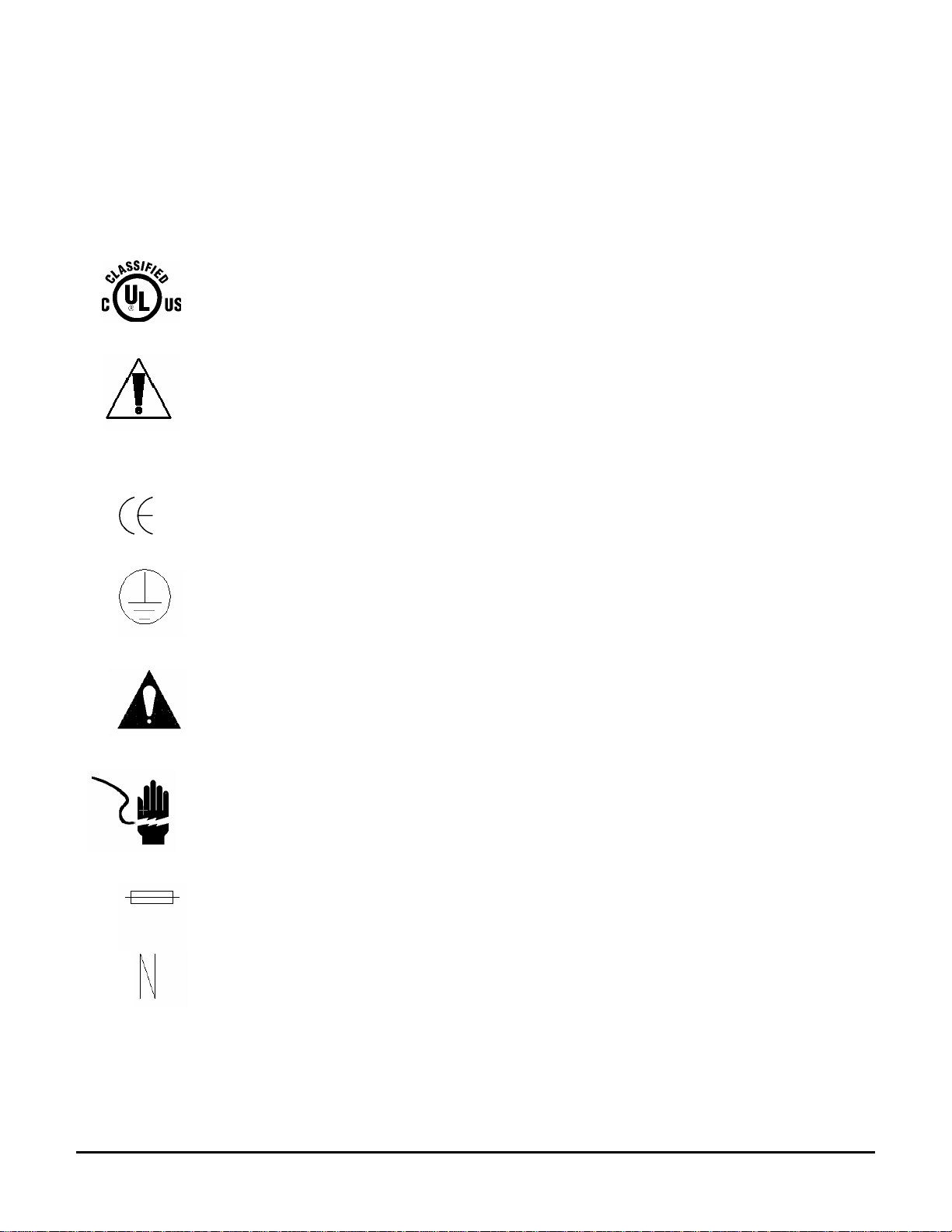
CENTURION EXCEL CENTURA CENTRY

Agency Approvals
Medical Electrical Equipment
With respect to electric shock, fire
And mechanical hazards only
In accordance with UL-2601-1/CAN/CSA C22.2 No.601.1
Classifications:
1. Protection against electrical shock (5.1, 5.2). Class I permanently connected.
2. Protection against harmful ingress of water (5.3). None.
3. Degree of safety in the presence of flammable anesthetics or oxygen (5.5). Not suitable
for use in the presence of flammable anesthetics or oxygen.
4. Mode of operation (5.6). Continuous.
5. Luminaire for Diagnosis (IEC60601-2-41).
6. Surgical Luminaire (IEC60601-2-41) Minor.
Electromagnetic compatibility for immunity
And emissions in accordance with
EN-60601-1-2 (1993) Group 1 Class A
Test report E190891-092004
Medical Electrical Equipment
Particular requirements for the safety of surgical
Luminaries and lumenaires for diagnosis
In accordance with IEC-60601-2-41
Intended use
The 21st Century Series are AC powered devices that provide a field of
illumination for general examination and surgery.
21st Century Series Service Manual (1003158 Rev F) Page i

21st Century Installation and Service Manual
Revisions
Revision
letter ECO
number Pages Affected Date
F 691 Manual revised to UL-2601 standard. 06-21-05
G 848 Centurion Excel Specifications updated. 02-21-05
21st Century Series Service Manual (1003158 Rev G) Page ii

Table of Contents
Section 1: Terminology
Definition of Terms
List of Symbols
Section 2: Specifications
Centurion Specifications
Centurion Excel Specifications
Centura and Centura F/O Specifications
Centry Specifications
Chuttle Track Specifications
Warranty
Section 3: Installation/Assembly
Ceiling Mount Pre-Installation Guidelines
Ceiling Rod Calculation Single Ceiling Mount
Ceiling Rod Calculation Double Ceiling Mount
Extended Ceiling Mount
Extended Ceiling Mount Installation
Single Ceiling Mount Installation
Double Ceiling Mount Installation
Wall Mounted Light Installation
Floor Stand Light Installation
Arm Assembly to Upright Pole Installation
Installation of Light Head to Arm
Chuttle Track Ceiling Track Mount
Chuttle Track Pre-Installation Requirements
Disassembly of the Track Mount Before Installation
Track Mount Installation Procedure
Section 4: Operating Instructions
Centurion and Centurion Excel Operation
Centura and Centura F/O Operation
Centry Operation
Section 5: Safety Instructions
Safety Tips
21st Century Series Service Manual (1003158 Rev G) Page iii

Table of Contents (continued)
Section 6: 21st Century Maintenance
Lamp Replacement Centurion and Centurion Excel
Initial Lamp Installation/Lamp Replacement Centry
Lamp Replacement Centura and Centura F/O
Fuse Replacement
Arm Adjustment
Head/Yoke Adjustment
Handle Sterilization
Cleaning Instructions
Maintenance Schedule
Section 7: Troubleshooting
General Troubleshooting
Section 8: Exploded Views and Parts List
Centurion, Centurion Excel and Centry Electric Schematic
Centura Electric Schematic
Centura with F/O Electric Schematic
Centurion Exploded View, Light Head Assembly
Centurion Light Head Assembly Part’s List
Centurion Excel Exploded View, Light Head Assembly
Centurion Excel Part’s List, Light Head Assembly
Centura Exploded View, Light Head Assembly
Centura Part’s List, Light Head Assembly
Centura F/O Exploded View, Light Head Assembly
Centura F/O Part’s List, Light Head Assembly
Centry Exploded View, Light Head Assembly
Centry Part’s List, Light Head Assembly
21st Century Series Service Manual (1003158 Rev G) Page iv

List of Figures
Figure Number and Description Page
Figure 1: Single Ceiling Mount Ceiling Rod Calculation 11
Figure 2: Double Ceiling Mount Ceiling Rod Calculation 12
Figure 3: Extended Ceiling Mount Installation 13
Figure 4: Sub-Assemblies for Single Ceiling Mount 15
Figure 5: Single Ceiling Mount Installation 17
Figure 6: Double Ceiling Mount Components 18
Figure 7: Wire Harness Positioning 20
Figure 8: Wire Channel 20
Figure 9: Double Ceiling Mount Installation 21
Figure 10: Wall Mount Dimensions 23
Figure 11: Wall Mount Installation 24
Figure 12: Floor Mount Dimensions 26
Figure 13: Floor Stand Lights Installation 27
Figure 14: Arm Assembly to Upright Pole Installation 28
Figure 15: Installation of Light Head to Arm 29
Figure 16: Light Head to Arm Electrical Connections 30
Figure 17: Track Assembly and Components 31
Figure 18: Mounting Pallet Perpendicular to Wood Joist 33
Figure 19: Mounting Pallet Parallel to Wood Joist 33
Figure 20: Mounting Pallet To a Suspended Ceiling 33
Figure 21: Suspended Ceiling Wood Bracing Detail (End View) 33
Figure 22: End Plate Removal 34
Figure 23: Side Panel Removal 35
Figure 24: Dress Cover Removal 35
Figure 25: Stop Pins Removal 36
Figure 26: Trolley Assembly Removal 36
Figure 27: Ceiling Rod and Roll Pin Installation 38
Figure 28: Power Cord Placement 39
Figure 29: Centurion and Centurion Excel Operation 40
Figure 30: Centura Spotlight Operation 41
Figure 31: Centura Spotlight Controls 42
Figure 32: Centura Fiber Optic Spotlight Model Operation 43
Figure 33: Centry Diagnostic/Specialty Light Operation 44
Figure 34: Centurion/Centurion Excel Lamp Replacement 48
Figure 35: Centry Lamp Replacement 50
Figure 36: Centura Lamp Replacement 52
Figure 37: Fuse Replacement 54
Figure 38: Centura Fiber Optic Fuse Replacement 54
Figure 39: Arm Adjustment 55
Figure 40: Head/Yoke Adjustment 56
Figure 41: Handle Sterilization 57
Figure 42: Electric Schematic for Centurion, Centurion Excel and Centry, 120VAC,
230 VAC, &240 VAC 62
21st Century Series Service Manual (1003158 Rev G) Page v

List of Figures (continued)
Figure 43: Electric Schematic for Centurion, Centurion Excel & Centry, 100VAC 63
Figure 44: Electric Schematic for Centura, 120VAC & 230 VAC 64
Figure 45: Electric Schematic for Centura 100 VAC 65
Figure 46: Electric Schematic for Centura Fiber Optic 115/120 VAC 66
Figure 47: Electric Schematic for Centura Fiber Optic 220/240 VAC 67
Figure 48: Centurion Light Head Assembly 68
Figure 49: Centurion Light Head Assembly, Bill of Materials 69
Figure 50: Centurion Excel Head Assembly 70
Figure 51: Centurion Excel Head Assembly, Bill of Materials 71
Figure 52: Centura Spotlight Head Assembly 72
Figure 53: Centura Spotlight Head Assembly, Bill of Materials 73
Figure 54: Centura Fiber Optic Head Assembly 74
Figure 55: Centura Fiber Optic Head Assembly, Bill of Materials 75
Figure 56: Centry Head Assembly 76
Figure 57: Centry Head Assembly, Bill of Materials 77
21st Century Series Service Manual (1003158 Rev G) Page vi

21st Century Series Service Manual (1003158 Rev G) Page 1
Section 1
Section 1: Terminology
Definition of Terms
I.E.C.
International Electrotechnical Commission
U.L.
Underwriter’s Laboratories
Medical Electrical Equipment
Electrical equipment intended to diagnose, treat the patient under medical supervision.
Electrical equipment that transfers energy to the patient.
Central Illuminance
Illuminance of light head measured at 1 meter from the light emitting area with no
obstructions. Expressed in Foot-candles or Lux.
Light Field Center
Point of maximum illuminance in lighted area. This is the reference point for light field
size and light distribution measurements.
Light Field Diameter
Diameter of the circle where illuminance reaches 10% of light field center illuminance.
Depth of Illumination
The overall distance from 1 meter where the central illuminance is reduced to 20%.
Shadow Dilution
Ability of the equipment to minimize the impact of shadows in the working area. Shadows
can be due to partial obstruction by the operator or other medical personnel.
Correlated Color Temperature
The color temperature of the light fixture when compared to a blackbody radiator
expressed in degrees Kelvin.
Total Irradiance
The total amount of energy imparted to the patient by the lighting system expressed in
Watts/meter squared.
Color Rendering Index (CRI)
A method of how well a light source will render other colors when illuminating them based
upon eight CIE chromaticity coordinates measured with a spectroradiometer.
Handle Sterilizable
Device when properly sterilized maintains a sterile area in order to handle it under aseptic
conditions when attached to the equipment.

21st Century Series Service Manual (1003158 Rev G) Page 2
Section 1
Definition of Terms (continued)
Light Head/Articulating Arm Assembly:
That part of the device that includes the light source, heat removal system, and light head
vertical positioning arm.
Extension Arm
Horizontal section of the positioning arm with pivots on both ends that is used to increase
the area covered by the light head and articulating arm.
Light Mounting
Support apparatus used to connect light head/articulating arm assembly to a fixed
surface, consisting of either a single or double ceiling mount, wall mount, or track mount.
Light head/articulating arm assembly may also be used with a mobile floor mount
Neutral Conductor
In an AC circuit, the return line for current.
Protective Earth Ground
The conductor used to connect the non-current-carrying metal parts of equipment,
raceways, and other enclosures to the system grounded conductor, the grounding
electrode conductor, or both, of the circuit at the service equipment or at the source of a
separately derived system.
Ft-Lbs.
Foot-pounds. The unit of measurement of torque that is caused by an off-center load.
21st Century Series Service Manual (1003158 Rev G) Page 3
Section 1
List of Symbols
U.L. Listing Marking
Read accompanying documents
C.E. Marking
Protective Earth Ground
Caution
Electric Shock Hazard
Fuse Marking
Neutral Conductor

21st Century Series Service Manual (1003158 Rev G) Page 4
Section 2
Section 2: Specifications
Centurion Specifications
Mechanical
Parameter Value
Weight
Head
Arm
Arm (Floor)
Wall Bracket Assy.
Floor Stand Assy.
Single Ceiling Mount
Dual Ceiling Mount
Approximately 9.10 lbs. (4.14 kg).
Approximately 12.5 lbs. (5.68 kg).
Approximately 11.4 lbs. (5.18 kg).
Approximately 3.00 lbs. (1.36 kg).
Approximately 43.0 lbs. (19.50 kg).
Approximately 14.5 lbs. (6.58 kg).
Approximately 16.0 lbs. (7.26 kg).
Dimensions
Head
Arm
Arm (Floor)
Floor Stand
15.8” (40.13 cm) Dia. X 6.0(15.24 cm) High
57.0” (144.8 cm) Long
38.5” (97.79 cm) Long
74.5” (189.23 cm) High
Rotations
Articulating Arm Vertical Movement
Articulating Arm Horizontal Movement
Articulating Arm/Yoke Interface
Yoke/Light Head Interface
+/- 40 Degrees travel
Approximately 345 Degrees
Approximately 540 Degrees
Approximately 190 Degrees
Electrical
Parameter Value
Voltages
Input Voltage
Bulb Voltage
110 - 125 VAC 50/60 Hz
210 - 230 VAC 50/60 Hz
11 – 12 VAC 90 W
Bulb life 2,000 hours (average)
Optical
Parameter Value
Reflector 15.0“ (380mm) Dia., Polished, Alzak
Performance
Central Illuminance
Color Temperature
Field Size
Irradiance
CRI
Approximately 3,900 ft-candles (41,980 Lux) @ 39.3” (1
m) (4,300 ft-candles (46,285 Lux) @ 36” (91.44 cm) )
Approximately 4,000 °K
6.00” (152.4 mm) Diameter @ 39” (914.4 mm).
155.2 W/m2
90
Environmental
Parameter Value
Operating Temperature
Storage Temperature Range 41 -104 ° F(5-40 °Celsius)
42 -113 ° F(5-45 °Celsius)
Humidity 10 - 90% Relative Humidity

21st Century Series Service Manual (1003158 Rev G) Page 5
Section 2
Centurion Excel Specifications
Mechanical
Parameter Value
Weight
Head
Arm
Arm (Floor)
Wall Bracket Assy.
Floor Stand Assy.
Single Ceiling Mount
Dual Ceiling Mount
Approximately 10.10 lbs. (4.58 kg).
Approximately 12.5 lbs. (5.68 kg).
Approximately 11.4 lbs. (5.18 kg).
Approximately 3.00 lbs. (1.36 kg).
Approximately 43.0 lbs. (19.50 kg).
Approximately 14.5 lbs. (6.58 kg).
Approximately 16.0 lbs. (7.26 kg).
Dimensions
Head
Arm
Arm (Floor)
Floor Stand
18” (45.72 cm) Dia. X 6.60 High (16.7 cm)
57.0” (144.8 cm) Long
38.5” (97.79 cm) Long
74.5” (189.23 cm) High
Rotations
Articulating Arm Vertical Movement
Articulating Arm Horizontal Movement
Articulating Arm/Yoke Interface
Yoke/Lamp Head Interface
+/- 40 Degrees travel
Approximately 345 Degrees
Approximately 540 Degrees
Approximately 190 Degrees
Electrical
Parameter Value
Voltages
Input Voltage
Bulb Voltage
110 - 125 VAC 50/60 Hz
210 - 230 VAC 50/60 Hz
11 – 12 VAC 90 W
Bulb life 2,000 hours (average)
Optical
Parameter Value
Reflector 16.50” (419.1 mm) diameter, aluminum, multi-facetted
Performance
Color temperature
Focal length
Central illuminance
Light field diameter
Depth of illumination
Light field diameter (d50)
Illuminance (one mask)
Illuminance (two masks)
Illuminance at bottom of standard tube
Illuminance at bottom of standard tube with one mask.
Illuminance at bottom of standard tube with two masks
Irradiance
CRI
4,000 °K
39” (1 meter)
6,520 foot-candles (70,180 Lux)
5.61” (142.5 mm)
42.00” (1067 mm)
3.76” (95.5 mm)
560 foot-candles (6,027 Lux)
1,974.19 foot-candles (21,250 Lux)
6,520 foot-candles (70,180 Lux)
743 foot-candles (7,998 Lux)
1,869.67 foot-candles (20,125 Lux)
81.21 W/m2
89
Environmental
Parameter Value
Operating Temperature
Storage Temperature Range 41 -104 ° F (5-40 °Celsius)
42 -113 ° F (5-45 °Celsius)
Humidity 10 - 90% Relative Humidity
21st Century Series Service Manual (1003158 Rev G) Page 6
Section 2
Centura and Centura F/O Specifications
Mechanical
Parameter Value
Weight
Head (Std.)
Head (Std. F/O)
Arm
Arm (Fiber Optic)
Arm (Floor)
Arm (Floor-Fiber Optic)
Wall Bracket Assy.
Floor Stand Assy. (Std and F/O)
Single Ceiling Mount (Std and F/O)
Dual Ceiling Mount (Std and F/O)
Approximately 7.20 lbs. (3.27 kg).
Approximately 8.00 lbs. (3.64 kg).
Approximately 13.3 lbs (6.05 kg).
Approximately 15.2 lbs. (6.91 kg).
Approximately 12.1 lbs. (5.50 kg).
Approximately 14.9 lbs. (6.77 kg).
Approximately 3.00 lbs. (1.36 kg).
Approximately 43.0 lbs. (19.50 kg).
Approximately 14.5 lbs. (6.58 kg).
Approximately 16.0 lbs. (7.26 kg).
Dimensions
Head
Arm
Arm (Floor)
Arm (Floor F/O)
Floor Stand
5.00” (12.7 cm) Dia. x 13.06” (33.17 cm) Long
57.0” (144.78 cm) Long
38.5” (97.79 cm) Long
41.5” (105.41 cm) Long
74.5” (189.23 cm) High
Rotations
Articulating arm vertical movement
Articulating arm horizontal movement
Articulating arm/Yoke interface
Yoke/Lamp Head interface
+/- 40 Degrees
Approximately 345 Degrees
Approximately 540 Degrees
Approximately 190 Degrees
Electrical
Parameter Value
Voltages
Input Voltage
Operating Voltage
110 - 125 VAC 50/60 Hz
210 - 230 VAC 50/60 Hz
20 VAC 150 W
Front Bulb Life
Fiber Optic Bulb Life 500 hours (average)
40 hours (average)
Optical
Parameter Value
Reflector 2.00” diameter Dichroic Glass
Performance
Central Illuminance
Color Temperature
Field Size (adjustable)
Irradiance
CRI
Approximately 1,700 ft-candles (18,300 Lux) @ 39.3” (1
m) (2,000 ft-candles (21,528 Lux) @ 36”)
Approximately 3,200 °K
Adjustable 3.00” (76.2 mm) to 16.0” (406.4 mm)
70.16 W/m2(1 m)
91
Environmental
Parameter Value
Operating Temperature
Storage Temperature Range 41 - 104 ° F (5 - 40 °Celsius)
41 - 113 ° F (5 - 45 °Celsius)
Humidity 10 - 90% Relative Humidity
21st Century Series Service Manual (1003158 Rev G) Page 7
Section 2
Centry Specifications
Mechanical
Parameter Value
Weight
Head
Arm
Arm (Floor)
Wall Bracket Assy.
Floor Stand Assy.
Single Ceiling Mount
Dual Ceiling Mount
Approximately 3.50 lbs. (1.59 kg).
Approximately 12.5 lbs. (5.68 kg).
Approximately 11.4 lbs. (5.18 kg).
Approximately 3.00 lbs. (1.36 kg).
Approximately 43.0 lbs. (19.50 kg).
Approximately 14.5 lbs. (6.58 kg).
Approximately 16.0 lbs. (7.26 kg).
Dimensions
Head
Arm
Arm (Floor)
Floor Stand
6.25” (15.88 cm) Dia. x 6.50” High (16.51 cm)
57.0” (144.78 cm)
38.5” (97.79 cm) long
74.5” (189.23 cm)
Rotations
Articulating arm vertical movement
Articulating arm horizontal movement
Articulating arm/Yoke interface
Lamp head rotation
+/- 40 Degrees
Approximately 345 Degrees
Approximately 540 Degrees
Approximately 190 Degrees
Electrical
Parameter Value
Voltages
Input Voltage
Bulb Voltage
110 - 125 VAC 50/60 Hz
210 - 230 VAC 50/60 Hz
12 VAC 75 W
Bulb life 2,000 hours (average)
Optical
Parameter Value
Reflector 5.00 “(127 mm) diameter, Dichroic Glass
Parameter Value
Performance
Central Illuminance
Color Temperature
Field Size
Irradiance
CRI
Approximately 1,750 ft-candles (18,835 Lux) @ 39.3” (1
m) (4,000 ft-candles (32,292 Lux) @ 24” (60.96 cm))
Approximately 4,000 °K
Approximately 10.0” (25.4 cm) Dia. at 39.3” (1 m) (6.0”
(152.4 mm) @ 24” (60.96 cm) )
115.5 W/m2(1 m)
91
Environmental
Parameter Value
Operating Temperature
Storage Temperature Range 41 - 104 ° F(5 – 40 °Celsius)
41 - 113 ° F(5 – 45 °Celsius)
Humidity 10 - 90% relative humidity

21st Century Series Service Manual (1003158 Rev G) Page 8
Section 2
Chuttle Track Specifications
Mechanical
Parameter Value
Weight
Single Track Assembly
Dual Trolley Model
Approximately 44.00 lbs. (19.95 kg).
Approximately 48.00 lbs. (21.77 kg).
Dimensions
Track (standard)
72” (182.88 cm) Long X 10 ½” Wide (26.67 cm)
X 5” (12.7 cm) High
Electrical
Power cable exiting the track can be connected to 115/120 VAC 60 Hz. or 230/240 VAC single
phase 50/60 Hz. power. The power supply routed to the track must be a 3 wire grounded type
capable of supplying 1400 Watts at 12 Amperes.
NOTE: Refer to Model/Serial label located on the arm assembly that will be mounted to
the track for proper voltage supply.

21st Century Series Service Manual (1003158 Rev G) Page 9
Section 2
Medical Illumination International, Inc.
Lighting Equipment
Limited Warranty
Medical Illumination International, Inc. Lighting Equipment is warranted against defective material and/or
workmanship, excluding normal replacement parts (e.g. bulbs or glass items), for a period of three (3)
years from the date of shipment. This warranty applies exclusively to the repair or replacement of parts
recognized as defective by Medical Illumination International, Inc., are in normal use, and have not been
modified or repaired by unauthorized personnel. This warranty supersedes all other guarantees or
warranties, expressed or implied.
In the event of a failure covered under this warranty, please take the following action:
1. Call the Medical Illumination Customer Service Department at (818) 838-3025.
A. Be prepared to give the model number, serial number, and full description of the failure.
B. Customer Service will attempt to solve the problem over the phone. If it becomes necessary to send the
product to the factory for repair, Customer Service will provide a Return Authorization number. No product
should be returned without a Return Authorization number.
2. Carefully package the light component (light head, arm assembly, or mount assembly) and return it, freight
prepaid and insured, with the Return Authorization number clearly marked on the box, to:
Medical Illumination International, Inc.
547 Library Street
San Fernando, CA 91340
RA#
Damage resulting from inadequate packing is not covered by this warranty and shipping insurance does not
cover damage from inadequate packing.
We recommend that the package be insured against loss or in-transit damage. Medical Illumination cannot be
responsible for in-transit loss or damage.
3. DAMAGE TO THE PRODUCT RESULTING FROM TAMPERING, ACCIDENT, ABUSE, NEGLIGENCE, OR
OTHER CAUSES UNRELATED TO PROBLEMS WITH MATERIAL AND/OR WORKMANSHIP, ARE NOT
COVERED BY THIS WARRANTY.
4. Warranty may be voided if equipment is found to have been installed incorrectly, resulting in equipment failure.
5. This warranty does not cover any labor costs associated with removing, re-packaging for shipment or
reinstalling this product. Such costs are the responsibility of the purchaser.
6. Medical Illumination International, Inc. will evaluate the returned product, repair as appropriate, and ship the
product back to you freight paid.
7. In the event non-warranty damage or failure is discovered, you will be contacted before repairs are performed.

21st Century Series Service Manual (1003158 Rev G) Page 10
Section 3
Section 3: Installation/Assembly
Ceiling Mount Pre-Installation Guidelines
SPECIAL NOTE: Installation and repair of this equipment should be performed by
qualified persons only. Medical Illumination International, Inc. does not warranty any
damage occurring as a result of improper installation.
It is recommended that this installation manual be completely reviewed prior to
installation.
Before installation, check to insure the following minimum conditions are provided:
•The structural ceiling mount should be designed to support a vertical load of at least 100 lbs.
and an off center moment of 300 ft-lbs. The structural mount should meet all local building
codes.
A structural mount that does not meet these minimum conditions can cause serious
injury and/or property damage.
•It is recommended that the equipment be mounted directly over a 4-0 junction box. If this is
not possible the input power supply lines should be wired in accordance with all applicable
building codes.
•The supply circuit line must be as follows:
120 VAC lights: 110 -120 VAC 60 Hz, single phase, three wire, capable of supplying 700
Watts @ 7 Amperes.
220 VAC lights: 230 -240 VAC, 50/60 Hz, single phase, three wire, capable of supplying 700
Watts @ 3.5 Amperes.
•The power supply circuit line must be routed and wired to the light head in compliance with
all applicable building codes.
Failure to provide a circuit meeting these minimum standards or complying with
local building codes can cause a shock hazard.
•Check the length of the ceiling rod supplied to make sure that it is the proper length to install
and operate the light without interference or over reach (See ceiling Rod Calculation pages
11-12).

21st Century Series Service Manual (1003158 Rev G) Page 11
Section 3
Ceiling Rod Calculation
Single Ceiling Mount
Use the following table to select the correct length ceiling rod for your application.
Ceiling Rod Calculation, Single Ceiling Mount
Ceiling Mounting
Height Ceiling Rod
Length
“X” Value
“Y” Value Head room to bottom
of extension arm
(y value-x value)
7’6”- 8’6”
(2,29- 2,59 m) 16”(406,4 mm) 22”(558,8 mm) 90-102”
(2,29-2,59 m) 68-80”
(1,72-2,02 m)
8’7”- 9’6”
(2,62 -2,89 m) 25”(635,0 mm) 31”(787,4 mm) 103-114”
(2,62-2.89 m) 72-84”
(1,82-2,13 m)
9’7”- 10’6”
(2,92- 3,20 m) 35”(889,0 mm) 41”(1041,4 mm) 115-126”
(2,92-3.20 m) 74-86”
(1,87-2,18 m)
Note: The Centry Diagnostic / Specialty Light is shown for reference. The dimensions
indicated also apply to the Centurion Diagnostic, Centurion Excel minor surgery light and the
Centura Spotlight.
Dimensions are approximate.
*Ceiling Rod Table applies to single and dual ceiling mounts.
FIGURE 1: Single Ceiling Mount Ceiling
Rod Calculation
NOTE: Longer
ceiling rods are
available for
higher ceilings.
See page 14 for
extended ceiling
mount
installation
instructions.

21st Century Series Service Manual (1003158 Rev G) Page 12
Section 3
Ceiling Rod Calculation
Double Ceiling Mount
Use the following table to select the correct length ceiling rod for your application.
Ceiling Rod Calculation, Double Ceiling Mount
Ceiling Mounting
Height Ceiling Rod
Length
“X” Value
“Y” Value Head room to bottom
of extension arm
(y value-x value)
7’6”- 8’6”
(2,29- 2,59 m) 16”(406,4 mm) 22.5”(571,5 mm) 89.5-102.5”
(2,27-2,57 m) 67.5-79.5”
(1,70-2,00 m)
8’7”- 9’6”
(2,62 -2,89 m) 25”(635,0 mm) 31.5”(800,1 mm) 102.5-114.5”
(2,60-2.87 m) 71.5-83.5”
(1,80-2,11 m)
9’7”- 10’6”
(2,92- 3,20 m) 35”(889,0 mm) 41.5”(1054,1 mm) 114.5-126.5”
(2,90-3.18 m) 73.5-85.5”
(1,85-2,16 m)
Note: The Centurion / Centura Combination Light is shown for reference. The dimensions
indicated also apply to all other combination of fixtures and dual mounting of the same light.
Dimensions are approximate
*Length measured when Arm is in horizontal position.
NOTE: Longer ceiling
rods are available for
higher ceilings. See
page 14 for extended
ceiling mount
installation instructions. FIGURE 2: Double Ceiling
Mount Ceiling Rod Calculation

21st Century Series Service Manual (1003158 Rev G) Page 13
Section 3
Extended Ceiling Mount
Use the following table to select the correct length ceiling rod for your application.
Extended Ceiling
Mount Kit P/N Ceiling Rod
Extension Length Mounting Height Extension P/N
1000976-49
20.0” (508,0 mm) 10’ 6”-11’ 8” (3,20-3,56 m) 1001263
1000976-63
34.0” (863,6 mm) 11’ 9”-12’ 10” (3,58-3,91 m) 1001264
1000976-77
48.0” (1219,2 mm)
12’ 11”-14’ (3,94-4,27 m)
1001265
MOUNTING SURFACE
Ceiling Casting
P/N 1001267
Wire Harness
Ceiling Rod Extension
(SEE TABLE)
Set Screws (2)
P/N 0001128
Dowel Pin
P/N 0001553
¼”-20 x 2” Bolt
P/N 0001311
Molex Connector
Casting Cover
P/N 1001270
Collar
P/N 1001271
Cap Nut
P/N 0001312
Set Screws (2)
P/N 0001544
35” Ceiling Rod
P/N 1001188
Distance to Floor
(
Mountin
g
Hei
g
ht
)
FIGURE 3: Extended Ceiling Mount Installation
This manual suits for next models
2
Table of contents
Other MEDICAL ILLUMINATION Medical Equipment manuals


Popular Medical Equipment manuals by other brands

Dynatronics
Dynatronics Dynatron 850 Plus Service manual

Arjo
Arjo Evenda EV-ACC12 Accessories Instructions

IMPLOX
IMPLOX Newborn Anne Directions for use

Lowenstein Medical
Lowenstein Medical JOYCE SilkGel Instructions for use

MDT
MDT SHAMPAINE 5100B Owner's and operator's manual

DMP Electronics
DMP Electronics XTLtouch Programming guide


NRS Healthcare
NRS Healthcare S18993 User instructions

BMC
BMC G2S BPAP Series user manual

eschmann
eschmann TD830 Instructions for use

College Park
College Park Odyssey K3 Technical instructions

Stryker
Stryker Surgistool 830 manual

Direct Healthcare Group
Direct Healthcare Group Dyna-Form Mercury Advance user manual