eschmann TD830 User manual
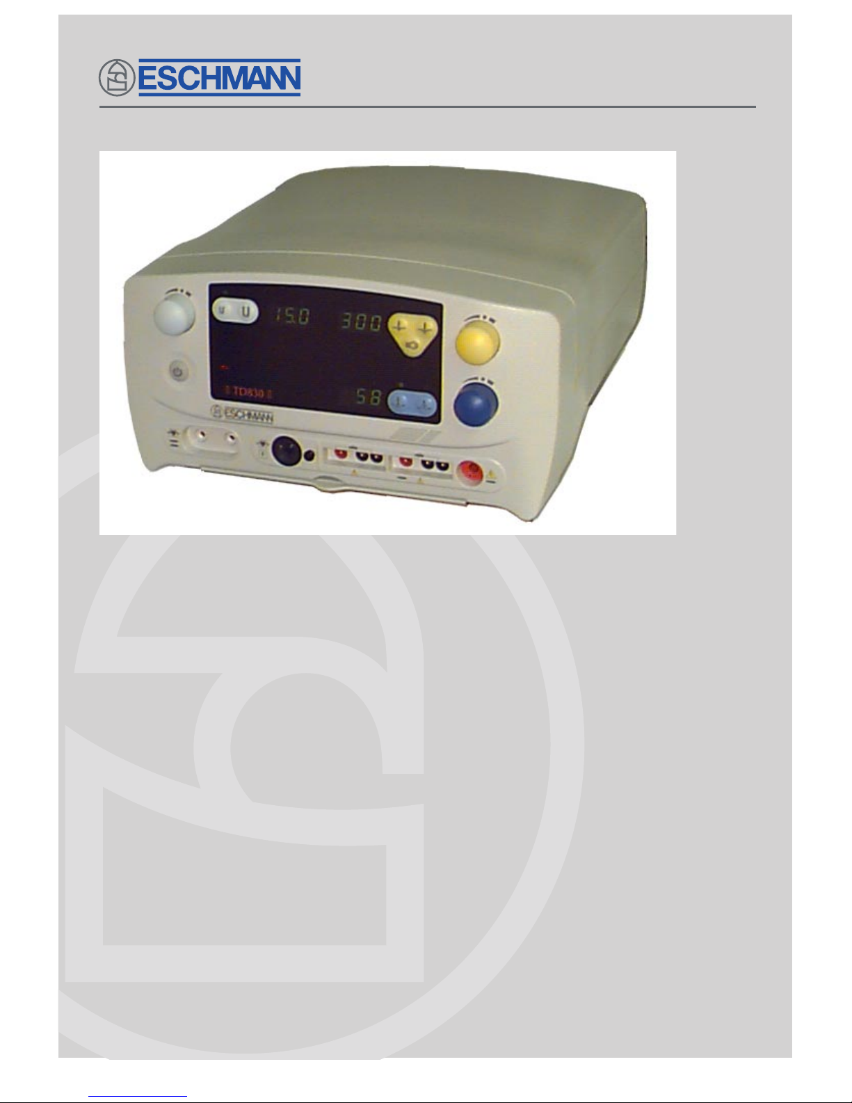
TD830
E LECT RO SURGICAL UNIT
Instructions for use
E-IM54f
698257

Instructions for use
Preliminary
Information
Technical data
Safety notes
and alarms
Operation
Cleaning, disinfection
and care
Accessories
Read these Instructions before use
Keep these ‘Instructions for use’ in a safe convenient place for future reference. Read in
conjunction with the relevant Publications detailed in the preliminary information section.
Eschmann After Sales Service Department
The Eschmann After Sales Service Department is staffed and equipped to provide advice and
assistance during normal office hours. To avoid delays when making enquiries, please quote the
Model and Serial Number of your Electrosurgical Unit which is shown on the Serial Number plate,
the location of which is shown below. Please ensure you include all alpha and numeric digits of
the Serial Number.
For further information visit www.eschmann.co.uk
All correspondence relating to the after sales service of Eschmann Equipment to be addressed to :
UK Customers
Eschmann Equipment, Peter Road, Lancing, West Sussex BN15 8TJ, England.
Tel: +44 (0) 1903 765040. Fax: +44 (0) 1903 875711.
Overseas Customers
Contact your local distributor. In case of doubt contact Eschmann Equipment.
Patents and Trade marks
The ESCHMANN name and logo are registered trade marks of Eschmann Holdings Limited.
“Eschmann Equipment” is a trading name of Eschmann Holdings Limited.
“TD830” is a trade mark of Eschmann Holdings Limited.
Patents : GB2276551, GB2146534,AU673883, ZA94/2173, US5480399,
EP617925, IEE69100 and other Patents Pending.
Copyright © 2006 Eschmann Holdings Limited
All rights reserved. This booklet is protected by copyright. No part of it may be reproduced, stored in a
retrieval system or transmitted in any form or by any means, electronic, mechanical, photocopying,
recording or otherwise without written permission from Eschmann Holdings Limited.
The information in this publication was correct at the time of going to print. The Company, however,
reserves the right to modify or improve the equipment referred to.
The CE marking affixed to the product certifies that it complies with the
European Medical Devices Directive 93/42/EEC and related legislation.
E-IM54f July 2006
The Serial Number plate
is located here, (view
from rear of unit).

E-IM54f P3/37
TD830
ELECTROSURGICAL UNIT
CONTENTS
1. PRELIMINARY INFORMATION
Preliminary information . . . . . . . . . . . . . . . . . . . . . . . . 4
2. TECHNICAL DATA
General . . . . . . . . . . . . . . . . . . . . . . . . . . . . . . . . . . . 5
Dimensions . . . . . . . . . . . . . . . . . . . . . . . . . . . . . . . . . 5
Electrical data . . . . . . . . . . . . . . . . . . . . . . . . . . . . . . . 5
Audible indicators . . . . . . . . . . . . . . . . . . . . . . . . . . . . 6
Visual indicators . . . . . . . . . . . . . . . . . . . . . . . . . . . . . 6
Safety.. .. . . . . . . . . . . . . . . . . . . . . . . . . . . . . . . . . . . 6
Duty cycle . . . . . . . . . . . . . . . . . . . . . . . . . . . . . . . . . . 7
Other symbols . . . . . . . . . . . . . . . . . . . . . . . . . . . . . . . 7
Button symbols . . . . . . . . . . . . . . . . . . . . . . . . . . . . . . 7
Alarm symbols . . . . . . . . . . . . . . . . . . . . . . . . . . . . . . . 8
Environmental conditions for transport and storage . . . 8
3. SAFETY NOTES & ALARMS
Do’s and Don’ts . . . . . . . . . . . . . . . . . . . . . . . . . . . . . . 9
Alarm circuits . . . . . . . . . . . . . . . . . . . . . . . . . . . . . . . 10
4. INTRODUCTION
General .. . . . . . . . . . . . . . . . . . . . . . . . . . . . . . . . . . 11
Operating modes / display option.. . . . . . . . . . . . . . . 11
Accessories . . . . . . . . . . . . . . . . . . . . . . . . . . . . . . . . 11
Associated Publications . . . . . . . . . . . . . . . . . . . . . . . 11
Equipment certification . . . . . . . . . . . . . . . . . . . . . . . 11
Electrosurgical techniques . . . . . . . . . . . . . . . . . . . . . 12
General . . . . . . . . . . . . . . . . . . . . . . . . . . . . . . . . 12
Monopolar electrosurgery . . . . . . . . . . . . . . . . . . . 12
Plate electrode . . . . . . . . . . . . . . . . . . . . . . . . 12
Footswitches . . . . . . . . . . . . . . . . . . . . . . . . . . 12
Active electrode handles . . . . . . . . . . . . . . . . . 12
Active cables . . . . . . . . . . . . . . . . . . . . . . . . . . 13
Active electrodes . . . . . . . . . . . . . . . . . . . . . . . 13
Fingerswitches . . . . . . . . . . . . . . . . . . . . . . . . 13
Power control . . . . . . . . . . . . . . . . . . . . . . . . . 13
Current paths . . . . . . . . . . . . . . . . . . . . . . . . . . 13
Accidental contact . . . . . . . . . . . . . . . . . . . . . . 13
Bipolar electrosurgery . . . . . . . . . . . . . . . . . . . . . . 13
General . . . . . . . . . . . . . . . . . . . . . . . . . . . . . .13
Flammable anaesthetics and spirits . . . . . . . . . . . 14
Implanted cardiac pacemakers . . . . . . . . . . . . . . . 14
General . . . . . . . . . . . . . . . . . . . . . . . . . . . . . . 14
Risks . . . . . . . . . . . . . . . . . . . . . . . . . . . . . . . . 14
Precautions . . . . . . . . . . . . . . . . . . . . . . . . . . . 14
Electrosurgical interference . . . . . . . . . . . . . . . . . 14
Using two electrosurgical units . . . . . . . . . . . . . . . 15
Using a flexible endoscope . . . . . . . . . . . . . . . . . . 15
Servicing . . . . . . . . . . . . . . . . . . . . . . . . . . . . . . . . . . 15
References . . . . . . . . . . . . . . . . . . . . . . . . . . . . . . . . 15
5. OPERATION
Routine check . . . . . . . . . . . . . . . . . . . . . . . . . . . . . . 16
Connection of accessories . . . . . . . . . . . . . . . . . . . . 16
Monopolar . . . . . . . . . . . . . . . . . . . . . . . . . . . . . . 16
Bipolar . . . . . . . . . . . . . . . . . . . . . . . . . . . . . . . . . 17
System check . . . . . . . . . . . . . . . . . . . . . . . . . . . . . . 17
Operating instructions . . . . . . . . . . . . . . . . . . . . . . . . 18
Monopolar standby mode . . . . . . . . . . . . . . . . . . . 18
Monopolar mode . . . . . . . . . . . . . . . . . . . . . . . . . . 18
USER 1 and/or USER 2 selection . . . . . . . . . . 18
Plate electrode . . . . . . . . . . . . . . . . . . . . . . . . 19
Fingerswitch/active electrode handle . . . . . . . . 19
Footswitches . . . . . . . . . . . . . . . . . . . . . . . . . . 19
Monopolar outputs . . . . . . . . . . . . . . . . . . . . . . 20
Power output . . . . . . . . . . . . . . . . . . . . . . . . . . 20
Bipolar Mode . . . . . . . . . . . . . . . . . . . . . . . . . . . . 21
Selecting bipolar forceps . . . . . . . . . . . . . . . . . 21
Connecting forceps . . . . . . . . . . . . . . . . . . . . . 21
Changing forceps . . . . . . . . . . . . . . . . . . . . . . 21
Footswitches . . . . . . . . . . . . . . . . . . . . . . . . . . 21
Power output . . . . . . . . . . . . . . . . . . . . . . . . . . 21
After use . . . . . . . . . . . . . . . . . . . . . . . . . . . . . . . . 21
Disconnecting accessories . . . . . . . . . . . . . . . . . . 21
Power output selection guide . . . . . . . . . . . . . . . . 21
Alarms . . . . . . . . . . . . . . . . . . . . . . . . . . . . . . . . . . 22
Alarm conditions . . . . . . . . . . . . . . . . . . . . . . . . . . 22
Alarm identifications and remedies . . . . . . . . . . . . 22
TABLE 1 - Power output selection guide . . . . . . . . . . 24
Output diagrams . . . . . . . . . . . . . . . . . . . . . . . . . . . . 25
6. CLEANING, DISINFECTION & CARE
Cleaning and disinfection . . . . . . . . . . . . . . . . . . . . . . 32
Cleaning the electrosurgical unit . . . . . . . . . . . . . . 32
Disinfecting the electrosurgical units . . . . . . . . . . . 32
Electrosurgical accessories . . . . . . . . . . . . . . . . . 32
Care . . . . . . . . . . . . . . . . . . . . . . . . . . . . . . . . . . 32
Service . . . . . . . . . . . . . . . . . . . . . . . . . . . . . . . . . 32
Additional information . . . . . . . . . . . . . . . . . . . . . . 32
Maintenance procedures . . . . . . . . . . . . . . . . . . . 32
Accessories . . . . . . . . . . . . . . . . . . . . . . . . . . . . . . . . 32
7. ACCESSORIES
Accessory list . . . . . . . . . . . . . . . . . . . . . . . . . . . . 33
ILLUSTRATIONS
1 - 5 . . . . . . . . . . . . . . . . . . . . . . . . . . . . . . . . . 34
6 - 8 . . . . . . . . . . . . . . . . . . . . . . . . . . . . . . . . . 35
9 - 10 . . . . . . . . . . . . . . . . . . . . . . . . . . . . . . . . 36
12 . . . . . . . . . . . . . . . . . . . . . . . . . . . . . . . . . . 37

P4/37 E-IM54f
1. PRELIMINARY INFORMATION
1.1 These Instructions for Use should be referred to for
details of the TD830 Electrosurgical Unit, REF 83-256-01,
83-257-02, 83-258-03, 83-259-04, 83-260-05, 83-261-01,
83-262-07, 83-263-08, and 83-264-09 (serial number
A9B0000 or above).
1.2 Within the text of this manual the term ‘coag’ is used
as a common abbreviation of the term ‘coagulation’.
1.3 Carefully remove the TD830 Electrosurgical Unit and
its associated accessories from the packing case(s).
1.4 Place the TD830 Electrosurgical Unit on a stable
convenient working platform, for example on the Eschmann
ST80 mobile trolley, purpose built for carrying
electrosurgical units.
1.5 The TD830 Electrosurgical Unit requires a mains
electrical supply corresponding to the voltage shown on
the electrical rating plate at the rear of the unit. Only use
the mains supply cable supplied. If the plug supplied pre-
fitted is not suitable it should be replaced with a suitable
plug with protective earthing contact.
1.6 If the plug is a fused type, a 10A fuse must be fitted.
CAUTION
It is most important that fuses of the correct
type, size and rating are installed (see Technical
Data).
CAUTION
Read these ‘Instructions for use’ carefully
before using this electrosurgical unit and note
ALL of the warnings, cautions and safety notes
contained within. Keep these ‘Instructions for
use’ close-to-hand at all times for reference.
Please note that Fig. 11 at the end of this manual
opens out so that it can be refered to easily whilst
reading this manual. It is the main figure
identifying the various parts of the TD830
Electosurgical Unit.
1.7 Ensure that the unit ‘mains’ switch (42 of Fig. 11) is
in the ‘O’ position and that the output controls are set to
minimum before connecting to, and switching ‘on’, the
mains supply. Acomplete systems check must be carried
out before using the Electrosurgery Unit (see Sections 5.10
to 5.17).
1.8 Instruction and Service Manuals should be readily
accessible for reference prior to and when operating,
cleaning and servicing the TD830 Electrosurgical Unit. All
manuals are available from Eschmann Equipment, see
inside front cover for address details.
Related Technical Publications
Service Manual for TD830
Publication number E-SM44, Part No. 698260
Eschmann accessory ‘Instructions for use’
Publication number E-IM50, Part No.604802

E-IM54f P5/37
TD830
ELECTROSURGICAL UNIT
2. 0 TECHNICAL DATA
GENERAL
The TD830 Electrosurgical Unit (or Surgical Diathermy
Unit) is classified as ‘HF surgical equipment’ 1
1- ‘HF surgical equipment’ is defined as, “Medical
electrical equipment including its associated accessories
intended for the performance of surgical operations, such as
the ‘cutting’ 2or ‘coagulation’ 3 of biological tissue by means of
high frequency (h.f.) currents”.
2- ‘Cutting’ is defined as, “Resection or dissection of body
tissue caused by the passage of high frequency current of high
current density at the active electrode(s)”.
3- ‘Coagulation’ is defined as, “Sealing of small blood
vessels or of body tissue caused by the passage of high
frequency current at the active electrode(s)”.
Equipment - High power electrosurgical unit with
monopolar and bipolar outputs
Type - Portable
DIMENSIONS
Width . . . . . . . . . . . . . . . . . . . . . . . . . . . . . .39.0 cm
Height . . . . . . . . . . . . . . . . . . . . . . . . . . . . . .19.0 cm
Length . . . . . . . . . . . . . . . . . . . . . . . . . . . . .42.5 cm
Weight . . . . . . . . . . . . . . . . . . . . . . . . . . . . . . .14 kg
ELECTRICAL DATA
(Note: Voltage factory set by transformer tapping, according
to model supplied.)
Power Supply . . . . . . . . . . . . . . . . . 230V a.c., 50-60Hz
or, 240V a.c., 50-60Hz
or, 220V a.c., 50-60Hz
or, 110V a.c., 50-60Hz
Current (max.) . . . . . . . . . 4.4A (230V) or, 4.2A (240V)
or, 4.6A (220V) or, 8.4A (110V)
Fuse rating (240V, 230V, 220V) . . . . . . . . . . . 250V, T5A
Fuse rating (110V) . . . . . . . . . . . . . . . 125V(min.),T10A
Fuse type . . . . . . . . . . . . . . . . . . . . . . . . . . . . . . 20 mm
Bipolar
Carrier frequency - 785kHz nominal, square wave.
Power control - Variable pulse group modu-lation set
by front panel control. Amplitude set by micro/macro range
buttons.
Load resistance for maximum output power
- 100 ohms (non-inductive) for Macro
- 50 ohms (non-inductive) for Micro
Test load - 100 ohms (non-inductive)
Output (bipolar)
Peak
Open
Crest Circuit
Symbol/Function Power factor Voltage
Coagulation
Micro range 17W ±20% Variable 150
Macro range 50W -20% Variable 230
Power and voltage output data diagrams are shown at the
end of section 5.
Monopolar
Carrier frequency - 475kHz nominal, square wave.
Power control - Variable amplitude set by frontpanel
controls. Preset pulse patterns set by mode switches.
Load resistance for maximum output power is 150 ohms
(non-inductive) for cut and pinpoint coag and 200 ohms
(non-inductive) for blend, specialist cut and spray coag.
Test load is 200 ohms (non-inductive) for cut and specialist
cut and 400 ohms (non-inductive) for blend, spray coag
and pinpoint coag.
Output (monopolar)
Output powers are measured to an accuracy of ±20%,
with a maximum power of 400 watts.
Peak
Open
Crest Circuit
Symbol/Function Power factor Voltage
Normal cut 345W(-20%) 1.9 1150
Blend 300W(±20%) 3.0 2200
Specialist cut 345W(-20%) 2.1 1500
Pinpoint coag. 170W(±20%) 5.1 2150
Spray coag. 79W(±20%) 8.7 4000
Power and voltage output data diagrams are shown at the
end of section 5.
+10%

P6/37 E-IM54f
AUDIBLE INDICATORS
Running tones *
Monopolar
Cut, blend or specialist cut 950Hz
Coagulation, pinpoint or spray 800Hz
Bipolar
Micro or macro 730Hz
(* Approximate values, adjustable volume)
Touch button
A ‘bleep’ indicates when any function button is pressed,
the volume is adjustable with running tones above.
Alarm
All modes - alternating two tone preset to maximum volume
(with flashing display).
VISUAL INDICATORS
Green lamp in mains ‘on/off’ switch to indicate power ‘on’
from the rear of the electrosurgical unit.
Digital displays and ‘function selected’ LEDs indicate power
‘on’ from the front of the electrosurgical unit
Three digital displays indicate
typical power*
in cut, coag
and bipolar modes. (Note: These can be set to display the
typical
power*
available in watts, or a numerical value up
to 10).
(
* typical
power
is an indication of the average power
delivered over a range of load resistances. It is less
thanthepowerdeliveredtothe rated loadformaximum
power.)
Power output ‘activated’ LED indicators for:
Cutting modes Yellow lamp
Coag modes Blue lamp
Bipolar mode Blue lamp
Green and bright green function selected LED indicators
above (or below) the relevant touch buttons detailed as
follows:
Monopolar:
Cut, blend, specialist cut (green)
Pinpoint coag (green)
Spray coag (bright green)
Bipolar:
Micro and macro power range (green)
SAFETY
General
Designed to comply with EN60601-1:1990 Medical
electrical equipment - general requirements for safety and
IEC60601-2-2: 1998 High-frequency surgical equipment -
particular requirements for safety (3rd edition).
General classification, Class 1, Type CF (Defibrillator
proof).
Drip-proof (IPX 1)
Patient leakage (risk) current: always less than 100
microamps to earth (ground) from all patient circuits at 230V
50Hz as required by EN60601-1:1990 for the unit in normal
condition (typically less than 10 microamps).
Battery
This equipment contains a nickel metal hydride battery. In
the event of failure of the display p.c.b. battery, or if the
electrosurgical unit is to be disposed of, it is not necessary
to remove the battery or to return it to Eschmann
Equipment. The battery charge life is six months from a
full charge of 48 hours. The battery charges automatically
when the unit is ‘on’.
Electrode isolation
The plate electrode circuit of this equipment is isolated
from earth at both high and low frequency. The bipolar
output is also fully isolated at both high and low frequency.
Class
Class 1 denotes that the equipment must be earthed via
the protective conductor in the 3-core mains cable
connected to a 3-pin plug.
Safety category
This symbol denotes that the equipment is of type
CF, i.e. that it complies with type CF leakage current
requirements. The symbol also denotes that the equipment
will not be damaged by defibrillator discharge and that the
plate electrode need not be removed from the patient if a
defibrillator is used.
Non-ionizing radiation
This symbol warns the user of the possibility of
non-ionizing radiation being emitted by this equipment.
Flammable gases
The TD830 equipment is not suitable for use in the
presence of a flammable anaesthetic mixture with air or
with Oxygen or Nitrous Oxide.
Protection
IPX 1 This symbol (drip proof) denotes that the equipment
meets the requirements of IEC529 for dripping water.

E-IM54f P7/37
TD830
ELECTROSURGICAL UNIT
DUTY CYCLE
The duty cycle rating of 10 seconds ‘on’, 30 seconds ‘off’,
specified on the serial plate as 10s:40s, indicates that the
equipment can be used at full output power in any mode
for 10 seconds with a 30 seconds rest period. The unit
can remain connected to the mains electrical supply with
the mains switch in the ‘on’ position continuously. The ‘on’
period at lower power levels can be extended.
OTHER SYMBOLS
Note: For numbers in brackets refer to Illustration 11 which
folds out at the end of this manual.
This symbol above item (33) indicates the running
tone volume control which has a minimum sound level of
45dBA.
This symbol above items (1, 14, 21 and 33)
indicates increasing power output (1, 14 and 21) and
increasing volume (33) for running tone and ‘bleep’ volume.
This symbol on the rear panel serial plate (39) and
above the mains inlet (40) indicates that the equipment is
for use on alternating current only.
This symbol on the rear panel serial plate
indicates that the mains input fuses, rating and type, are
as shown below the symbol.
The symbol on the front panel denotes that the plate
electrode is isolated from earth at high frequency. (Note:
The plate electrode is also known as the dispersive, neutral,
return, indifferent or patient plate electrode and is often
simply called the ‘pad’).
The symbol on the front panel adjacent to the active
outputs (24 to 28) denotes dangerous voltages.
The symbol on the rear panel serial plate warns the
user to read the accompanying documents, the
‘Instructions for use’.
The symbol above sockets (25, 26, 27 and 28)
denotes connection socket for a two button electrode
handle (fingerswitch type).
The symbol adjacent to sockets (24, 26 and 31)
denotes connection socket for a non-switched active
handle actuated by a footswitch.
This symbol on the monopolar standby selection
button (32) (monopolar ‘on/off’ toggle button) indicates
standby mode for part of the equipment only.
The symbols Iand adjacent to the mains ‘on/off’ switch
(42) indicate the ON and OFF positions respectively.
The symbol adjacent to item (34) indicates the
‘equipotentiality’ connection point. (Means for connection
of a potential equalization conductor).
The symbol adjacent to button (35) signifies the button
in the non-pressed (i.e. normal) state. (Digital display on
the front of the electrosurgical unit is a typical power figure,
e.g. 0-200watts for monopolar blend).
The symbol adjacent to button (35) signifies the button
in the pressed (i.e. activated) state. (Digital display on the
front of the electrosurgical unit shows a numerical value
up to 10).
The symbol adjacent to sockets (36, 37 and 38)
indicates the connection point for footswitches.
The symbol SN indicates serial number.
The symbol REF indicates catalogue number.
The symbol indicates date of manufacture.
BUTTON SYMBOLS
Press to select bipolar - micro range
Press to select bipolar - macro range
Press to select monopolar - cut
Press to select monopolar - blend
Press to select monopolar - specialist cut
Press to select monopolar - pinpoint coag.
Press to select monopolar - spray coag.

P8/37 E-IM54f
ALARM SYMBOLS
PCM - Indicates the ‘Plate continuity monitor’ alarm has
been activated.
PAM - Indicates the ‘Plate attachment monitor’ alarm has
been activated.
PEM - Indicates the ‘Patient earth monitor’ alarm has been
activated.
PVM - Indicates the ‘Plate voltage monitor’ alarm has
been activated.
EPM - Indicates the ‘Excess power monitor’ alarm has
been activated.
- Indicates the ‘Multiple activation’ alarm has been
activated.
!- Indicates an internal fault has been detected (see section
5 ‘Alarm conditions’ for details).
ENVIRONMENTAL CONDITIONS FOR
TRANSPORT AND STORAGE
Ambient temperature range:
-30°C to +50°C
Relative humidity range:
30-90% RH non-condensing
Atmospheric pressure range:
1060hPa down to 690hPa

E-IM54f P9/37
TD830
ELECTROSURGICAL UNIT
3.0 SAFETY NOTES & ALARMS
Attention to the following points is necessary
in order to reduce the risk of accidental burns
during the use of this electrosurgical unit. Other
safety notes and warnings are also given within
the text of this manual and these should be
noted before using this electrosurgical unit.
DO:
♦Use only Eschmann accessories, in particular active
and plate electrodes and cables which should
preferably be no more than 3 metres in length. All
Eschmann accessories are rated above the
corresponding maximum peak output voltage of this
electrosurgical unit (see graphs in section 5). For
reference Eschmann accessories can be used safely
at the following h.f. peak voltages:
Bipolar active - 400 V peak
Monopolar active - 4000 V peak
Monopolar plate electrode - 2250 V peak
♦Use bipolar techniques in preference to monopolar,
whenever possible. For surgical procedures on parts
of the body having a relatively small cross-sectional
area, the use of bipolar techniques may be desirable
to avoid unwanted coagulation.
♦Seek approved qualified advice (e.g. cardiology
department) before using this electrosurgical unit on
patients with implanted pacemakers or other active
implantstoavoidinterferenceordamagetotheimplant.
Monitor such patients carefully.
♦Set power output controls to the minimum setting
before use and select the minimum power setting to
achieve the desired effect.
♦Check all cables and accessories routinely before
use.Inparticular, electrodecablesandendoscopically
usedaccessoriesforpossible damagetotheinsulation.
♦Ensuretheentireareaof the plate electrode is reliably
attached to the patient’s body and as close to the
operating field as possible.
♦Store temporarily unused active electrodes such that
they are isolated from the patient [e.g. use a quiver
(REF 83-186-38) to hold active accessories when not
in use].
DO NOT:
♦Donotuseuninsulatedforceps,monopolarorbipolar.
♦Do not place monitoring electrodes close to the
operating site. When high frequency surgical
equipment (i.e. electrosurgical equip-ment) and
physiological monitoring equip-ment are used
simultaneously on the same patient, any monitoring
electrodes should be placed as far as possible from
thesurgicalelectrodes. Needlemonitoring electrodes
are not recommended. In all cases, monitoring
systems incorporating high frequency current limiting
devices are recommended.
♦Do not allow active cables to drape across or contact
the patient's body or contact the cables or leads of
other equipment.
♦Do not use flammable anaesthetics, flammable
solvents or oxidizing gases such as nitrous oxide
(N2O) or oxygen if the surgical procedure is carried
out in the region of the thorax or head, unless these
agents are sucked away.
♦Do not allow the patient's body to touch conductive
objects. Thepatientshouldnotcomeintocontactwith
metal parts which are earthed or which have an
appreciablecapacitancetoearth, e.g. operation table,
supports, etc. The use of antistatic sheeting is
recommended for this purpose.
♦Do not use hook type active cables (with or without
adapters designed for use with hook type cables) use
4 mm or 8 mm plug type active cables.
♦Do not reuse disposable plate electrodes.
♦Do not rely solely on surgical gloves to provide
insulation.
♦Do not allow ‘skin-to-skin’ contact (e.g. between the
arms and body of the patient), this can be avoided, for
example by the insertion of adequate dry gauze.

P10/37 E-IM54f
Attention to the following points will prolong
the life and efficiency of your
electrosurgical unit and will help to avoid the
risk of accidents, or damage:
DO:
♦Switch off and disconnect from the mains electrical
supply prior to cleaning the equipment and when it is
not in use.
♦Grasptheconnector(s) not the cablewhenconnecting
and disconnecting cables and leads from the
equipment.
♦Contactthe hospitalelectronicsengineer orEschmann
After Sales Service Department if the equipment fails
to function after checking.
♦Ensure the equipment is serviced regularly (at least
every six months). Contact Eschmann After Sales
Service Department for details.
DO NOT:
♦Useafaulty unit asfailurecouldresult in anunintended
increase of output power.
♦Servicethisequipmentunlessyouaresuitablyqualified
to do so.
Alarm Circuits
3.1 The unit has several alarm circuits as detailed in
the following sections.
Plate Continuity Monitor (PCM).
3.2 Ensures that the unit cannot be used in the
monopolar mode with an electrically defective plate
electrode or cable. It does not monitor the contact between
the plate electrode and the patient’s body. It is reset
automatically when a satisfactory plate electrode and cable
are connected to the unit.
Plate Attachment Monitor (PAM).
3.3 Ensures that the unit cannot be used in the
monopolar mode if a divided plate electrode is attached to
the patient’s body incorrectly. Applies only when a divided
plate electrode is used and will not operate if monopolar is
switched ‘off’ by the monopolar standby selection button.
Excess Power Monitor (EPM).
3.4 The unit monitors its output power in monopolar and
bipolar modes, compares this with the maximum allowed
power under single fault conditions and alarms, disabling
output, if the delivered power exceeds the allowed value
by more than a certain margin.
Patient Earth Monitor (PEM).
3.5 The PEM circuit detects a low impedance path
between the patient and earth. It also reduces the chances
of secondary contact electrosurgical burns. The circuit
detects earth contact paths while the plate electrode is
attached to the patient and the unit, when a monopolar
fingerswitch or footswitch is pressed, but before the
monopolar output is activated. If such an earth path is
present, the alarm will operate until the path has been
removed and the unit reset by switching ‘off’ and ‘on’ at the
mains supply switch or if a pressed monopolar footswitch
or fingerswitch is released.
Plate Voltage Monitor (PVM).
3.6 Is designed to prevent dangerous electrosurgical
voltages appearing on the patient’s body. Such voltages
could occur because of insulation faults in the active circuit
or because the active electrode is in contact with an earthed
object and could cause burns at points of contact between
the patient and conductive objects. This alarm will operate
when monopolar output power is ‘on’ and the fingerswitch
or footswitch is operated. This monitor will not detect a
poor contact between the plate electrode and the patient.
Note: Under specific electrical conditions, with the plate
electrode completely detached from the patient, the PVM
could alarm.
Multiple Activation Alarm.
3.7 Operates if more than one fingerswitch or footswitch
is pressed at the same time in a given user section (i.e.
monopolar USER 1 or USER 2 or bipolar). It will
automatically be reset when ALL activations have been
released. This alarm will also operate if a footswitch or
fingerswitch is being activated when the unit is switched
‘on’. (Note: This could indicate a damaged accessory
locked in the ‘on’ position).
Internal error alarm
3.8 Operates if an internal fault arises such as power
being detected when not enabled by a footswitch or
fingerswitch.

E-IM54f P11/37
TD830
ELECTROSURGICAL UNIT
4.0 INTRODUCTION
GENERAL
Note: For numbers in brackets refer to Illustration 11 which
folds out at the end of this manual.
4.1 The TD830 electrosurgical unit provides two outputs
both for high power monopolar cut and coag (on a first
come first served basis), together with a separate output
for bipolar coag. Bipolar coag output is available
simultaneously with either monopolar output. The unit
incorporates touch button controls, seven segment LED
(light emitting diode) displays and LED visual indicators.
4.2 The digital displays can show two scale modes, one
shows the
typical
power available in watts the second
shows a numerical value up to 10 (the latter is only
displayed whilst digital display range selection toggle button
(35) is held pressed).
Note: The power delivered depends on the resistance
between the active electrode and the plate electrode (or
between the tips of bipolar forceps) at the time the power
is applied. This resistance can vary widely and many times
per second during the application of h.f. output.
4.3 The unit incorporates several alarm code indicators
as detailed in the Technical Data section. Innovative safety
features include a divided plate electrode monitoring
system called the PlateAttachment Monitor (PAM) as well
as the standard Eschmann Plate Voltage Monitor (PVM),
Patient Earth Monitor (PEM) , and Plate Continuity Monitor
(PCM). An Excess Power Monitor (EPM) and a Multiple
activation alarm are also included. A high frequency
leakage control circuit is included in the monopolar mode.
4.4 Within this manual the terms USER 1 and USER 2 are
used to distinguish between the two monopolar outputs.
The bipolar output is fully independent of the monopolar
output and can be considered as USER 3.
OPERATING MODES / DISPLAY OPTION
Monopolar mode
4.5 The monopolar operating mode offers a choice of
fingerswitch or footswitch control of ‘cut’ or ‘coagulation’
outputs for USER 1. Fingerswitch operation utilises the
Eschmann two-button fingerswitch whilst footswitch control
requires the use of an active electrode handle in conjunction
with one of a range of electrical footswitches.
Bipolar mode
4.6 Bipolar coag is an efficient method of effecting
haemostasis, and closure of vessels such as Fallopian
tubes. It is extremely safe to use, as the main current path
is between the tips of the bipolar forceps and the tissue
held between them is directly in view of the surgeon at all
times.
4.7 A plate electrode is not required and safety is
increased even further as two power range outputs are
available allowing precise setting of the power output.
4.8 The bipolar mode of operation offers a choice of
footswitch, electrical or pneumatic.
Monopolar standby mode
4.9 The unit can be switched into monopolar standby
mode, in which only bipolar power is available, using
monopolar standby selection button (32). This button is a
toggle switch, each press of the button will turn monopolar
mode ‘on’ (if ‘off’) or ‘off’ (if ‘on’). This button (32) can be
considered as an ‘on/off’ switch for monopolar, the
advantage being that if only bipolar outputs are required
and monopolar standby mode is selected, no plate
electrode needs to be connected to the unit. (If monopolar
standby mode is not selected for ‘bipolar use only’ and a
patient plate electrode is not connected to the unit the PAM
alarm or PCM alarm will activate). The unit is in monopolar
standby mode when only the digital display for bipolar can
be seen illuminated.
Digital display options
4.10 The digital displays normally show the
typical
power*
available in watts. The digital displays can also show a
numerical value up to 10 (maximum). To display the power
setting as a numerical value up to 10 press and hold the
digital display range selection button (35). The display will
revert to the normal setting (and display the
typical
power*
available in watts) when the button is released. (
* typical
power
is an indication of the average power delivered over
a range of load resistances. It is less than the power
delivered to the rated load for maximum power.)
ACCESSORIES
4.11 The equipment is designed to be used with the
Eschmann range of active, plate and bipolar cables. The
front panel is colour coded, PALE BLUE for bipolar,
YELLOW for monopolar cut, blend and specialist cut, and
BLUE for monopolar coag. For a list of all accessories and
an index of accessory illustrations, see section 7.
ASSOCIATED PUBLICATIONS
4.12 This manual contains preparation for use, and
operation instructions only. For a detailed technical
description, together with complete maintenance
procedures including an illustrated parts list refer to the
TD830 Service Manual E-SM44 (part number 698260).
EQUIPMENT CERTIFICATION
4.13 The electrosurgical unit fully complies with the major
international safety standards (see Technical Data).
CAUTION
This electrosurgical unit is to be operated by
medically qualified personnel only.

P12/37 E-IM54f
ELECTROSURGICAL TECHNIQUES
General
4.14 When using electrosurgery, it must always be
remembered that its purpose is to cut, destroy or modify
tissue. This can occur at any point on the body where the
concentration of electrical current becomes sufficiently
high. Under fault, or misuse conditions, this current
concentration can occur on points on the body other than
the desired operation site and can cause burns.
4.15 To help reduce the possibility of such accidental
burns, the unit is fitted with a leakage limiting circuit in the
monopolar section. This circuit detects the conditions that
may lead to an increased possibility of accidental burns
from leakage and limits the leakage current accordingly.
The HF leakage limiter does not generate an alarm. In
addition, the following paragraphs give guidance for the
safe use of the electrosurgical unit.
4.16 With monopolar electrosurgery, the surgeon uses a
single point electrode to concentrate high frequency electric
current in the body tissues close to the electrode tip. If the
operating site is linked to the bulk of the body only by a
tissue path of small cross-sectional area, e.g. Fallopian
tube or penis, the surgical effect of the electrosurgery can
extend along it from the electrode with undesirable results.
4.17 Normally the surgeon will have ensured that the
operating site is bounded by a bulk of tissue into which the
current can disperse, so that the cut or coagulating effect
is limited to the tissues close to the electrode. The current
then disperses into the body and leaves it by way of the
relatively large plate electrode, having passed harmlessly
through any intervening tissue and organs.
4.18 In contrast, with bipolar electrosurgery there is no
plate electrode and the surgical effect occurs between the
tips of a pair of insulated bipolar forceps held by the
surgeon. The legs of the forceps constitute two
electrosurgical active electrodes.
Monopolar Electrosurgery
Plate Electrode
4.19 The plate electrode is also known as a neutral
electrode, passive, return, dispersive, indifferent or patient
plate electrode or simply as the ‘pad’.
4.20 Always use a plate electrode of proven technical
design and safety, and in strict accordance with the
application instructions issued with the plate electrode.
Burns at the site of the plate electrode are the most
common form of electrosurgical accident. Maximum
contact with the patient's skin must be maintained
throughout the surgical procedure. The following points
should also be noted:
♦ Do not apply any plate electrode over bony
protuberances, metal implants, folds of skin, scar
tissue, hairy areas, any form of skin discoloration, an
injury, or to limbs with restricted blood supply.
♦ Do not apply the plate electrode adjacent to ECG
electrodes and cables, or to an area where fluids
could pool.
♦ With babies and small children the plate electrode
should always be applied to the trunk section of the
body to give maximum contact with the skin. It is
unsatisfactory to attach the plate electrode to small
limbs where overlap of the plate electrode ends can
occur.
♦ Subject to application instructions, the plate electrode
should be on a smooth, resilient, muscular site well
supplied with blood vessels and as close as possible
to the operating area. The site should be clean and
dry,andshavedof excessive hair. The plate electrode
should be securely attached with its whole area in
contact with the patient’s body.
♦ Do not cut or modify the plate electrode in any way.
♦ Do not reuse disposable adhesive plate electrodes,
as adhesive failure could occur.
4.21 Adhesive plate electrodes (REF 83-122-42 and 83-
122-46) with detachable cables, should only be used with
a connector cable (REF 83-122-93) that requires complete
insertion of the connector tab. This ensures that contact
between the tab and any conductive object cannot occur.
Footswitches
4.22 Footswitches (REF 83-581-09 and 83-581-13 for
yellow, or REF 83-581-17 and 83-581-25 for blue, or twin
footswitches REF 83-109-39 and 83-109-47) must always
be under the direct control of the surgeon or the designated
assistant. Precautions must be taken to prevent
footswitches contacting the operating table base, castors
of trolleys, or other equipment under which they could be
trapped in the ‘on’ position.
4.23 During a surgical procedure and when the power
output is not activated, check that:
♦ The green ‘mains’ supply lamp is ‘on’.
♦ The bipolar and monopolar (cut and coag) power
activated LEDs are ‘off’.
♦ The audible ‘running tone’ is ‘off’.
Active Electrode Handles
4.24 During surgery, when an active electrode handle
(REF 83-140-20 without cable, or REF 83-141-01,
83-141-36, 83-141-28 and 83-141-44 with cable) or
fingerswitch (REF 83-582-06, 83-583-97 or 83-585-94) is
not in use, it should be put in an electrosurgical quiver
(REF 83-186-38) or similar receptacle. Do not put the
handle or fingerswitch:
♦ On the patient drapes.
♦ With other instruments.
♦ On the electrosurgical unit cabinet or on any other
theatre equipment.
This will further reduce the possibility of electrosurgical
burns due to accidental activation of the electrosurgical

E-IM54f P13/37
TD830
ELECTROSURGICAL UNIT
unit. Also do not use active electrode handles that have
cables fitted with ‘hook’ type connectors (those detailed
above are suitable for use with this unit). The absence of
exposed metal parts on pin or jack plug designs reduces
the risk of operator burns compared to cables with the
‘hook’ type design.
Active Cables
4.25 Only active cables supplied by Eschmann should
be used. This is of particular importance, as cables with
inadequate insulation can cause burns due to insulation
failure.
4.26 It is good practice to ensure that active cables are
correctly positioned when in use and are not allowed to
drape across the patient's body or across other cables.
4.27 Active cables of the ‘hook’ type have been replaced
by pin or jack plug designs (REF 83-135-12, 83-137-17,
83-138-06 and 83-138-22) any of these are suitable for
use with this unit. Old style cables with ‘hook’ type
connectors should not be used. The absence of exposed
metal parts on pin or jack plug designs reduces the risk of
operator burns compared to cables with the ‘hook’ type
design.
4.28 Active cables 3 metres long should be used in normal
situations, even if it means repositioning the electrosurgical
unit. Longer types, of 5 metres or more, should only be
used where the electrosurgical output is a fixed distance
from the operation table, e.g. with certain types of pendant
supply, or with lamina airflow curtains. Longer cables
increase the risk of electrical or mechanical hazard.
Active Electrodes
4.29 The correct type of active electrode (see section 7)
should always be used. Electrodes should be kept clean
during use either by wiping with a solvent on a sterile swab
or by using a sterile abrasive pad.
CAUTION
Ensure that the active cable is unplugged from
the unit when cleaning electrodes during a
surgical procedure.
4.30 Ball type coag electrodes should be discarded if the
surface becomes pitted. Do not sterilize electrodes which
are designed as ‘single use disposable’ (also see the leaflet
detailed in section 1, supplied with all accessories ).
Fingerswitches
4.31 For many procedures, ‘on/off’ control of cut and coag
outputs by means of buttons on a fingerswitch offers the
surgeon more precise control. Reusable fingerswitches
have only a limited number of re-sterilization cycles.
Regular testing and inspection is therefore essential. Do
not sterilize and reuse ‘single use’ types.
4.32 Do not connect footswitches to the USER 1 output
of the electrosurgical unit when a fingerswitch is being used
to control the USER 1 output.
Power Control
4.33 Use only the minimum power control setting
necessary to produce the desired electrosurgical effect.
If in doubt start at a low setting and increase the output
in small steps until the desired effect is produced.
4.34 If, during a surgical procedure, the output
appears to drop or the electrosurgical performance
decreases, stop and check the plate electrode for
correct application and connection before increasing
the control setting. Also check all active connections.
4.35 If only one type of output is required, i.e. cut or
‘coagulation’, it is good practice to set the other output
controls to minimum.
Current Paths
4.36 The path of an electrosurgical current through a
patient's body should, whenever possible, be the
shortest path. If it is suspected that this path could be
bypassed, for example between limbs, an insulating
medium should be used.
4.37 It is advisable that skin to skin contact between
parts of the patient's body, for example between the
arms and the trunk, should be avoided. Dry gauze or
other material should be used to provide separation.
Accidental Contact
4.38 Do not allow contact to occur between any part
of the patient's body and any metal or conductive
material, such as parts of the operation table,
anaesthetic screens or drip stands.
Bipolar Electrosurgery
General
4.39 Bipolar coag provides a very safe and precise
means of controlling bleeding in many types of surgery,
and can be used in conjunction with monopolar
techniques where cutting, or higher coagulation powers
are required.
4.40 With bipolar techniques, the electrosurgical
current flows mainly between the tips of the bipolar
forceps or between the contact points of a special
purpose electrode and therefore does not require a
plate electrode. Bipolar electrosurgery is safer than
monopolar, the main safety requirements are:
♦ Always use Eschmann bipolar accessories.
♦ After sterilization, always ensure that the
accessories and cable connector are completely
dry.
♦ Always ensure that accessories are sterilized by
a process compatible with the accessory, consult
the accessory leaflet provided with all Eschmann
accessories (publication number E-IM50 part
number 604802).

P14/37 E-IM54f
Flammable Anaesthetics and Spirits
4.41 The use of flammable anaesthetics and nitrous oxide
(N2O) or oxygen should be avoided if a surgical procedure
is to be carried out in the region of the thorax or the head,
unless these agents are removed by suction. Flammable
agents used for cleaning or disinfecting, or as solvents of
adhesives should be allowed to evaporate before the
application of electrosurgery. (Also see WARNING above
section 6.1).
4.42 There is a risk of pooling of flammable fluids under
the patient or in body depressions such as the umbilicus
and in body cavities such as the vagina. Any fluid pooled
in these areas should be mopped up or removed by suction
(for gaseous fluids) before the equipment is used.
4.43 Attention is drawn to the danger of ignition of
endogenous gases (i.e. those gases produced within the
body). Some materials, e.g. cotton wool and gauze, when
saturated with oxygen may be ignited by sparks produced
in normal use of the equipment.
Implanted Cardiac Pacemakers
General
4.44 If in monopolar electrosurgery the intervening tissue
and organs contain an implanted pacemaker and its leads,
it is possible under certain conditions that the
electrosurgical current will have undesirable effects. The
following notes offer guidance on the risks and on possible
precautions.
WARNING
For patients with cardiac pacemakers or other
active implants, a possible hazard exists
because interference with the action of the
pacemaker may occur or the pacemaker may
be damaged. In case of doubt, approved
qualified advice should be obtained.
Risks
4.45 Operating with electrosurgical equipment on patients
who have an implanted pacemaker incurs the risks of
affecting the pacemaker's operation, either by direct contact
or by radiated interference, and of inducing burns at the
pacemaker electrode implantation site. Clearly the risks
are very much lower with bipolar than with monopolar
electrosurgery, because of the highly localised current path.
Precautions
4.46 Recommendations published in the U.S.A.
(References ¹ and ²) suggest that an implanted pacemaker
should be unaffected, or only revert to fixed-rate operation,
if the electrosurgical active electrode and plate electrode
are kept a few inches away from the pacemaker pulse
generator and its electrode leads; while to avoid burns to
the myocardium at the electrode site, or possible ventricular
fibrillation, they should remain at least 15 cm away from
the heart.
4.47 It will also be sensible to choose a location for the
plate electrode which puts the path of electrosurgical
current through the patient's body as far as possible from
the heart and from the pacemaker and its leads.
4.48 If the pacemaker is programmable, it is suggested
that it is set to either the VVT (ventricular sensing and
triggering) or the V00 (fixed rate) mode (preferably the latter
if the patient is not at particular risk from a competitive
rhythm) so that it functions as a fixed rate pacemaker during
the surgical procedure.
4.49 It is further recommended(References ¹ and ²) that
the peripheral pulse be monitored during the course of
electrosurgery, and (Reference ²) that precautions be taken
to ensure that the patient's well-being is maintained in the
event of interference with pacemaker operation. By using
the electrosurgical equipment in short bursts, it is
suggested (References ¹ and ²) that, at most, only one or
two beats will be affected.
WARNING
More severe consequences, local heating and
destruction of the pacemaker circuit
(Reference ¹), would result if an electro-surgical
electrode touched the pacemaker.
Electrosurgical Interference
4.50 Electrosurgical equipment can produce interference
with other electromedical apparatus used in the operating
theatre. Particular attention should be given to the selection
of ECG monitors with good interference rejection if it is
desired to monitor the patient when the electrosurgical
equipment is active.
4.51 In certain conditions a reduction in ECG interference
can be obtained by placing the ECG electrodes closer
together than normal. Modern monitors with high input
isolation allow electrode placement close to the
electrosurgical plate electrode, if required.
4.52 It is inadvisable to use mobile telephones or ‘walkie-
talkie’ equivalent equipment close to electrosurgical or any
other medical electrical equipment.
4.53 To minimize the possibility of electrical interference
from an arc, between the active electrode and the patient,
affecting the TD830, it is good practise, in common with all
electrosurgical units, to keep them as far as is reasonably
possible from the surgical site.

E-IM54f P15/37
TD830
ELECTROSURGICAL UNIT
Using Two Electrosurgical Units
4.54 This electrosurgical unit has dual monopolar outputs
(first come first served) and simultaneous bipolar output.
It is therefore very unlikely that another electrosurgical unit
would need to be used on the same patient at the same
time, however if it is necessary follow the guidelines
detailed in section 4.55.
4.55 In certain procedures it is convenient or even
essential that two electrosurgical units are used on the
patient at the same time. There is no reason why such
operations should not be safely carried out if the following
points are observed:
♦ Do not use a fully floating output unit with an earth
referenced unit or even a partially floating unit, for
example:
♦ Eschmann TD411 or DS402 and a Valleylab
Force 4
♦ Eschmann TD411 or DS402 and a GU Solstar
or any older GU unit.
Note: All Eschmann units have fully floating
outputs and any two may be used in
combination.
♦ Always use two plate electrodes, one for each unit.
Never join plate cables or overlap plate electrodes.
♦ Position each plate electrode as close as possible to
the respective operation site. Do not allow
electrosurgical current paths to intersect, e.g. if the
main procedure is in the thoracic region, the plate
electrodeforthisunitshould be placed on the patient’s
back, buttocks, or upper thigh. If the secondary
procedure is vein removal from the leg, the second
plate electrode should be placed on the thigh or calf
of this leg.
♦ For maximum safety use fingerswitches wherever
possible. This reduces the possibility of inadvertent
activation of either unit’s output. Always use two
quivers, one for each active handle or fingerswitch.
Using a flexible endoscope
4.56 To ensure that the endoscope connection socket is
not used without a documented procedure in place, the S-
Lead socket (29, Fig.11) is blanked of with a plug to avoid
inadvertent use. Before removing this plug the following
notes should be considered when writing a procedure for
the use of this electrosurgical unit with an endoscope.
a. To avoid the risk of potential burns caused by h.f.
voltages on the body of the flexible endoscope some
users may prefer to connect the endoscope to the
TD830 Electrosurgical unit. This is accomplished
using an S-Lead [REF 83-139-41 (Olympus 9mm),
or REF 83-139-49 (Pentax 8mm)] connected to the
S-Lead socket (29, Fig 12) of the TD830
Electrosurgical unit and the flexible endoscope.
b. When using a flexible endoscope low power settings
only should be used (e.g. maximums of 30% for cut,
50% for pinpoint coagulation). Also because of the
high voltage waveform of spray coagulation it should
only be used at very low power settings see 3 below.
c. It is important to ensure that the flexible endoscope
used is compatible with the voltages produced by
the TD830 Electrosurgical unit. The maximum
voltages produced by the TD830 Electrosurgical unit
for each mode and display setting are shown in the
graphs at the end of section 5. These should be
compared to the voltage rating of the flexible
endoscope. (Note: Flexible endoscopes complying
with IEC60601-2-18 should detail their voltage rating
in their accompanying documentation. If in doubt
consult the flexible endoscope manufacturer).
SERVICING
4.57 It is recommended that electrosurgical safety
checks and routine servicing are carried out at regular
intervals (every six months) and only by Eschmann trained
personnel or Eschmann trained hospital engineers,
otherwise the warranty could be infringed.
4.58 Read the information given in this manual carefully
before using, cleaning, sterilizing, or servicing the
electrosurgical unit.
References
¹ ‘Optimal resources for implantable cardiac
pacemakers’ (Section on electromagnetic
interference) - a report by the Inter-Society
CommissionforHeartDiseaseResources,published
by the American Heart Association in their journal
‘Circulation’ (1983), 68(1):232A-233A.
² ‘Electrosurgical device interference with implanted
pacemakers’ - a question and answer section of the
‘Journalofthe American MedicalAssociation’. (1978),
239(18:1910).

P16/37 E-IM54f
5.0 OPERATION
WARNING
1) This electrosurgical unit is to be operated
by medically qualified personnel only.
2) Note that interference produced by the
operation of this unit may adversely influence
the operation of other electronic equipment.
3) While the electrosurgical unit is activated
(i.e. the running tone can be heard and power
activated indicators are illuminated) do NOT
touch the patient with a contact area of less
than 10cm2. This is especially important when
monopolar mode is being used at high power
settings.
4) Do not touch a monopolar or bipolar active
electrode with its active cable plugged into the
electrosurgical unit, even when changing the
electrode.
5.1 Before use ensure the details covered in the
preliminary information sections 1.5 to 1.7 have been
performed and the routine checks below in section 5.2 have
been completed. Connect the required accessories as
detailed in sections 5.3 to 5.9 and then carry out a systems
check detailed in sections 5.10 to 5.17 before using the
unit.
ROUTINE CHECK
5.2 Routine checking should be limited to external
checks of the unit, and must include all accessories and
cables. Routine checks must be carried out each time the
unit is used as follows:
WARNING
If in doubt, discard suspect component and
substitute with one of known function,
continuity and condition.
♦ Mains electrical supplycable/cord. Examinemains
electrical supply plug for condition and correct
attachment to cable/cord. Check condition of cable/
cord insulation over its entire length.
WARNING
Do not repair a damaged disposable plate
electrode or reusable plate electrode. Always
substitute a new plate electrode and, if
necessary, the cable. Always ensure that a
supply of new plate electrodes is readily
available.
♦ Plate electrode. With reusable types, examine the
platecable and plug for signs ofwear. Ensure that the
insulationoftheconnectingcableisingoodcondition.
♦ Accessory cables/cords(reusablemonopolaractive
and bipolar types). Examine all cables for condition
and attachment to end fittings.
Note: All active cables are subject to deterioration
caused by repeated sterilization and should be
renewed regularly.
♦ Fingerswitches. Check buttons on fingerswitches
for function and free action.
Note: Allfingerswitcheshavealimitedlifeandshould
be renewed regularly.
♦ Footswitches. Check all footswitch cables and
connectors for condition. Check all switches for
correct function and free action.
CONNECTION OF ACCESSORIES PRIOR
TO USE or SYSTEMS CHECK
Note: For numbers in brackets refer to Illustration 11 which
folds out at the end of this manual.
Monopolar
5.3 There is a choice of active cable connections to the
lower front panel of the unit for the monopolar outputs:
♦ A three-pin fingerswitch connector can be plugged
into active fingerswitch sockets (27 and 28) for USER
2 and active fingerswitch sockets (25 and 26) for
USER 1.
♦ A single active cable with 4 mm plug (footswitch
operated) can be connected to active electrode
socket (26) for USER 1.
CAUTION
Incorrect insertion of a single 4mm monopolar
active plug into either of the USER 1
fingerswitch sockets (25) can cause damage
to the TD830 if the output is energized by a
footswitch.
♦ A single active cable with 8 mm plug (footswitch
operated)canbe connected to activeelectrodesocket
(24) for use by USER 1 only
Note: This overrides any cables plugged into the
USER 1 sockets (25 and 26).
CAUTIONS
Only one of the above active connections
should be connected to the unit at any one time
for USER 1.
If an adapter is connected to the unit and it does
not have an active cable connected to it, the
adapter must be removed from the unit.

E-IM54f P17/37
TD830
ELECTROSURGICAL UNIT
If an 8 mm active adapter is connected to the
unit, the fingerswitch sockets (25 and 26) are
electrically disconnected.
5.4 For USER 1 connect an Eschmann fingerswitch (Fig.
6) to fingerswitch sockets (25 and 26).
5.5 Alternatively for USER 1 plug an 8mm active cable
(BOVIE) into the 8mm active electrode socket (24) in
combination with a footswitch (Fig. 4) yellow for cut, and/
or blue for coag, which should be plugged into either
monopolar footswitch socket (38). These sockets are
identical, the function is determined by the colour of the
footswitch. The Eschmann Twin footswitch can also be
used to provide both cut and coag functions (see Fig. 4).
5.6 Still another option for USER 1 is to connect an
active electrode handle (Fig. 5) to 4mm active electrode
socket (26) and plug a footswitch (Fig. 4) yellow for cut,
and/or blue for coag, into either monopolar footswitch
socket (38). These sockets are identical, the function is
determined by the colour of the footswitch. The Eschmann
Twin footswitch can also be used to provide both cut and
coag functions (see Fig. 4).
5.7 For USER 2 connect an Eschmann fingerswitch to
sockets 27 and 28.
Notes:
♦ Sockets (25 and 26) and (27 and 28) are designed to
accept the Eschmann fingerswitch.
♦ The footswitch controlled active connection system
using the 8 mm (BOVIE) socket (24) requires either
thecombinedhandleandcableREF83-141-28or83-
141-44 (Fig. 5) or the separate handle REF 83-140-
20 (Fig. 3) with cable REF 83-138-06 or 83-138-22
(Fig. 7).
♦ For foot control, use one of the range of Eschmann
footswitches together with a non-switching active
handle.
WARNING
When a fingerswitch or hand controlled active
handle is in use for monopolar USER 1, the
footswitch(es) must be disconnected from the
electrosurgical unit.
CAUTION
For safety, when using only one monopolar
mode, set the unused output control to
minimum e.g.
¨ For coag only, set cut power output control
(14) to minimum.
♦ For cut/blend only, set coag power output
control (21) to minimum.
Bipolar
5.8 Connect a bipolar cable REF 83-041-55 to the
bipolar output socket (31) and either a white electric
footswitch REF 83-581-76 (Fig. 10) to the bipolar electric
socket (37) or a white pneumatic footswitch REF 83-581-
68 (Fig. 10) to the bipolar pneumatic socket (36). Do not
connect both types of footswitch at the same time.
5.9 If the electrosurgical unit is only to be used in the
bipolar mode select the monopolar standby mode (see
section 5.18). The monopolar digital displays (8 and 23)
will not be illuminated and this will enable use of the unit
without the need to connect a plate electrode to the unit
(PAM alarm or PCM alarm will activate if a plate electrode
is not attached to the unit and it is not in monopolar standby
mode).
SYSTEMS CHECK
Note: For numbers in brackets refer to Illustration 11 which
folds out at the end of this manual.
WARNING
If the unit fails any of the following checks it
must not be used until the faults have been
repaired and the checks have been
successfully repeated.
5.10 Connect the required accessories as detailed in
sections 5.3 to 5.9.
5.11 Connect unit to mains power supply using the cable
supplied connected to the mains inlet (40), and if the supply
socket is controlled by a switch, ensure that it is switched
‘on’. Select mains switch (42) to ‘I’ (on). The green lamp
inside the mains switch (42) will come ‘on’ and the front
panel displays (indicators and digital) will illuminate.
5.12 The unit may be in monopolar standby mode, if it is
monopolar displays will not be illuminated and monopolar
will be disabled unless the monopolar standby button (32)
is pressed (see section 5.18). The unit will power up in the
modes and settings in use when the unit was last switched
off, unless the battery powering the memory has failed or
lost charge, in which case it will power up in monopolar
standby mode.
5.13 Press each selector touch button (3, 5, 11, 13, 15,
19 and 20) in turn and check that the green or bright green
indicator adjacent to each touch button comes ‘on’ (2, 4,
10, 12, 16, 17 and 18 respectively). Each time a selector
touch button is pressed there is an audible ‘bleep’ to signify
the button has been pressed (also see the first note after
section 5.15).
5.14 Set monopolar cut, monopolar coag and bipolar
power output controls (14, 21 and 1 respectively) to their
minimum levels (fully anticlockwise).
5.15 If the monopolar mode is to be used ensure that all
monopolar electrodes are safe and activate the unit in all
the monopolar modes to be used, for each USER, by

P18/37 E-IM54f
pressing a fingerswitch cut or coag button or by pressing
the appropriate footswitch, yellow for cut, blue for coag.
Check that the relevant power activated indicators
illuminate, yellow (9) or blue (22) for cut or coag respectively
and that the audible running tone can be heard.
Notes:
♦ The volume of the running tone and the selector
button‘bleep’can be adjusted with the volumecontrol
(33) on the back of the unit. This should be adjusted
using a screwdriver of suitable size.
♦ Coagulation output is obtained only by pressing the
fingerswitch blue coag button or the blue footswitch.
♦ Cut outputisobtainedonly bypressingthe fingerswitch
yellow cut button or the yellow footswitch.
5.16 If the bipolar output is to be used ensure that the
bipolar electrode is safe and activate the output by pressing
the white footswitch connected (either electric or
pneumatic). Check that the blue power activated indicator
(7) illuminates and that the audible running tone can be
heard.
5.17 Check that the following alarms are functioning
correctly by the test methods that follow:
PAM - To test the PAM alarm attach the divided plate
electrode to the divided plate cable with the divided
plate cable plugged into the unit. The PAM alarm
should operate with the plate electrode not attached
to the patient.
PCM- To test thePCM alarm remove thenon-divided plate
electrode from the non-divided plate cable with the
non-divided plate cable plugged into the unit. The
PCM alarm should operate.
PEM - To test the PEM alarm with the plate electrode
attachedtotheunitallow the plate electrode to contact
the equipotentiality point (34) at the rear of the unit
using a bare metal part of the plate and not a part
covered by adhesive. With cut and coag power levels
both adjusted to zero (for safety) the PEM alarm
should operate when a USER 1 footswitch or
fingerswitch (whichever is connected to the unit) or a
USER 2 fingerswitch is pressed .
Note: This test is not possible with a capacitive plate
electrode.
-To test the multiple activation alarm press both a cut
and coag footswitch or fingerswitch control, the alarm
should operate.
The other alarms (PVM, EPM and !) cannot easily be
checked by the user without special test equipment or by
using procedures that could lead to accidental burns. The
function of the EPM alarm should be checked regularly, in
accordance with the Service Manual (see section 1.8).
OPERATING INSTRUCTIONS
Note: For numbers in brackets refer to Illustration 11 which
folds out at the end of this manual.
♦ Unit settings (e.g.rangeselectionandmode selection)
are stored in the unit's memory during power-off
periods and will not need reselecting when power is
reapplied. Power settings will also be maintained
during power ‘off’ so long as the control knobs are not
moved.
♦ The audible running tones operate at different
frequenciesforeachofthethreeoutput groups(bipolar,
monopolarcutandmonopolarcoag)asdetailedinthe
‘Technical data’ section.
If a monopolar user activates power at the same time
(but after) a bipolar user the tone will continue at the
bipolarfrequencyuntil the bipolaruserstopsactivation
when the monopolar user’s frequency will start
(assuming the monopolar user is still activating the
unit). If the monopolar user only activates the unit for
a short period during a long activation by the bipolar
user then the monopolar user’s frequency will not be
heard. The same principles apply if a monopolar user
isactivatingpowerandabipolaruserstartstoactivate
power at the same time.
Monopolar standby mode
5.18 If the unit is in monopolar standby mode only bipolar
operation is available, monopolar is disabled and the
monopolar digital displays (8 and 23) will not be seen. The
unit is switched in and out of standby mode be pressing
the monopolar standby button (32). The switch ‘toggles’
standby mode ‘on’ or ‘off’ each time the button is pressed,
monopolar standby mode is selected when the digital
displays for monopolar (8 and 23) are not illuminated.
Monopolar mode
USER 1 and/or USER 2 selection
5.19 The TD830 can be used by two monopolar operators
USER 1 and USER 2 independently of each other but not
simultaneously. Each user can have their own active output
under their own control operated by footswitch or
fingerswitch for USER 1 and fingerswitch only for USER 2
(see sections 5.3 to 5.7)
5.20 USER 1 and USER 2 can be using either cut or
coag but the mode set within cut or coag must be the same
and the power level set must similarly be the same (unless
changed between each USER’s application of power).
5.21 Because USER 1 and USER 2 cannot both be
delivering power at the same time, power is available on a
‘first-come-first-served’ basis. (i.e. if USER 1 is using power
and USER 2 presses a fingerswitch to demand power, none
will be available and visa versa). Also note that power will

E-IM54f P19/37
TD830
ELECTROSURGICAL UNIT
not become available to the second user until the first user
has finished using power and the second user has released
and reapplied demand (via footswitch or fingerswitch) after
the first user has finished.
Plate electrode (required for monopolar mode only)
5.22 If the electrosurgical unit is to be used in monopolar
mode and a plate electrode is not connected to the plate
electrode connector socket (30), the unit will alarm (PCM
or PAM) and the audible two-note tone will sound and the
displays will flash. If a non-divided plate cable is being used,
then connecting a non-divided plate electrode will stop the
alarm. If a divided plate cable is being used then connecting
a divided plate electrode and applying the divided plate
electrode correctly to the patient’s body will stop the alarm.
WARNINGS
1) Whichever type of plate electrode is used,
it is most important that the application
instructions, issued with the plate electrode,
are strictly followed.
2) Ensure the pin on the plate connector (or
adapter) is fully inserted into the plate electrode
socket (item 30, Fig. 11) before energising the
output.
5.23 A plate continuity monitoring circuit (PCM) initiates
the audiovisual alarm system if there is a break in the non-
divided plate cable, or a faulty connection in the non-divided
plate electrode circuit. The electrosurgical output will be
instantly cut off and will not be restored until the fault is
corrected.
5.24 If a divided plate cable and divided plate electrode
are being used, the unit will alarm (PAM) if the divided
plate electrode is not making sufficiently good contact with
the patient’s body or if the divided plate electrode or its
connector system is faulty.
5.25 Apply a plate electrode to the patient in strict
accordance with the application instructions supplied with
the plate electrode and connect the plug to the plate
electrode socket (30) on the front panel of the unit.
Note: The Eschmann Flexoplate must be used with
adapter REF 83-207-56, Fig. 1.
5.26 If the required surgical effect is not obtained with
the normal power setting, check the following before
increasing power:
♦ The plate electrode is correctly positioned, and is in
contact with the patient.
♦ The plate electrode cable is intact, and is plugged into
unit plate electrode socket (30).
♦ The active electrode is correctly fitted in its holder and
the active cable is correctly connected to the unit.
Check that the cable is in good condition.
Guidance on power output settings is given in sections
5.53 to 5.55 and in Table 1.
Fingerswitch / active electrode handle
5.27 A fingerswitch or active electrode handle must be
treated with extreme care at all times.
WARNINGS
1) When either a fingerswitch or an active
electrode handle is connected to the unit, its
location should be closely noted. It should
never be allowed to contact other instruments.
2) During surgery, when an active electrode
is not in use, it should always be put in an
electrosurgical quiver or similar receptacle.
This is most important when both bipolar and
monopolar electrodes are required for the same
surgical procedure.
3) Similarly do not touch USER 1 active
electrode when USER 2 output is activated and
visa versa.
4) Do not touch a bipolar active electrode
when monopolar is activated and visa versa.
5.28 Connect the required cable and active fingerswitch
to the fingerswitch sockets (27 and 28) for USER 2 and
fingerswitch sockets (25 and 26) for USER 1 as detailed
in sections 5.3 to 5.7.
5.29 Alternatively for USER 1 connect an active cable
with a 4mm plug into active socket (26) or an active cable
with an 8mm plug (BOVIE) to active socket (24) as detailed
in sections 5.5 to 5.7.
Footswitches
5.30 Eschmann footswitch(es) (Fig. 4) can be plugged
into either footswitch socket (38). With either cut (11), blend
(13) or specialist cut (15) output selected, pressing a yellow
(cut) footswitch illuminates the yellow power activated
indicator (9), and the cutting running tone will sound.
5.31 With either pinpoint coag (19) or spray coag (20)
selected, pressing a blue (coag) footswitch illuminates the
blue power activated indicator (22), and the coag running
tone will sound.
5.32 The Eschmann twin footswitch (Fig. 4) has an angled
platform with two light-action switches for cut and coag.
Colour coded bars provide foot location and protection
against accidental operation.

P20/37 E-IM54f
WARNINGS
1) Footswitches should be used with care at
all times and should always be under control
of the surgeon or designated assistant, as
inadvertent operation could have serious
results.
2) Footswitches should be kept clear of areas
where other personnel could accidentally press
them, also ensure that they do not get wedged
under theatre equipment.
3) Select mains switch (42) to ‘O’ (‘off’) as
soon as electrosurgery is completed.
Monopolar cut and coag outputs
5.33 Monopolar cut and coag outputs are obtained by
pressing monopolar selector touch buttons (11, 13, 15, 19
or 20), then setting output controls (14) for cut or (21) for
coag to the required levels, and then using the fingerswitch
or pressing the appropriate footswitch.
5.34 'Running' tones are generated whenever monopolar
cut or coag outputs are activated by footswitch or
fingerswitch. The volume of the running tones is adjustable
by the volume control (33) on the back of the unit. A small
screwdriver is needed for this adjustment. This does not
affect the pitch (i.e. frequency) of the tones.
5.35 Yellow indicator (9) is illuminated when cut power is
activated and blue indicator (22) is illuminated when coag
power is activated,
5.36 For a cutting current with increased haemostatic
effect, select blend touch button (13). Adjusting the setting
of cut control (14) will only change the power output, it will
not change the nature of the blended current. Blended
output is only obtained by pressing the yellow (cut)
fingerswitch button, or by pressing the yellow (cut)
footswitch.
5.37 For maximum cutting speed, particularly in urology,
select the specialist cut touch button (15).
5.38 The two coag modes are selected by touch buttons
(19) pinpoint coag and (20) spray coag. The pinpoint mode
provides low voltage coagulation for most types of surgery.
The spray coag mode activates a separate generator circuit
which provides a waveform that reduces the cutting effect
to a very low level but provides fast coagulation by allowing
an arc to form between the electrode and the tissue. The
waveform is a series of high energy single pulses. Spray
coag allows non-contact coagulation of tissue that tends
to adhere to active electrodes.
Note: Spray coag (indicated with the bright green LED) is
not recommended for laparoscopic and endoscopic
procedures where its high voltage waveform can damage
the insulation of laparoscopic and endoscopic instruments,
especially flexible endoscopes. Most urological
endoscopes are suitable for spray coag. If in doubt check
that the voltage rating of the laparoscopic or endoscopic
instrument is at least as high as the maximum spray coag
open circuit voltage of this electrosurgical unit (see
Technical Date section).
CAUTION
Although power output in the spray mode is
lower than in the pinpoint mode (79W rather
than 170W maximum), the effect on tissue is
much greater in the spray mode. Until
experience is gained, only low control settings
should be used.
5.39 Select pinpoint or spray coag at touch buttons (19)
or (20) respectively and note correct selection by
illumination of a green indicator (17) for pinpoint coag and
a bright green indicator (18) for spray coag adjacent to the
applicable touch buttons.
Power output
WARNING
Apparent low power or failure of the unit to
function correctly at the normal operating
settings may indicate faulty application of the
plate electrode or poor contact in its
connections. In this case, the application of the
plate electrode and its connections should be
checked before selecting a higher output
power.
5.40 The output power level is adjusted by the power output
controls (14) and (21) for cut and coag modes respectively.
Turning the knob clockwise increases the power output
which is displayed digitally on displays (8) and (23)
respectively.
5.41 Digital power displays (6, 8 and 23) can show a
second type of output setting display by pressing the digital
display range selection button (35) on the rear of the unit.
The two available digital displays are as follows:
♦
When button 35 IS NOT pressed.
The
typical
power output available for a given setting
of the respective power output control is displayed.
The calibration is in watts for a
typical
resistance (see
Technical Data section for the maximum power
available for each output mode).
♦
When button 35 IS pressed.
The power output selected for a given setting of the
respective power output control is displayed as a
numerical value up to 10.
Table of contents
Other eschmann Medical Equipment manuals
Popular Medical Equipment manuals by other brands

BIOTRONIK
BIOTRONIK Lumax 540 VR-T DX Technical manual

Great Bear Healthcare
Great Bear Healthcare Libra Instructions for use

Asskea
Asskea M30 Plus Instructions for use

Invitrogen
Invitrogen Bandmate Automated Western Blot Processor user guide

Parks
Parks 915-BL OPERATING & SERVICE MANUAL

asis
asis Active Forever Lung Exerciser instruction manual