Medical International Research Spirolab III User manual

SpirolabIII – User’s Manual Code MIR 980067 REV 0 Page 1 / 47
Spirolab III
User’s Manual Rev.0
Issued on 21/06/06
Approved on 21/06/06
SpirolabIII – User’s Manual Code MIR 980067 REV 0 Page 2 / 47
Thank you for choosing a product from MIR
Medical International Research
The original packaging contains one of the following spirometers, complete with its standard accessories:
PRODUCT without oximetry option CODE PRODUCT with oximetry option CODE
SpirolabIII bag 672685 SpirolabIII bag 672685
SpirolabIII device 910551 SpirolabIII device plus oxy 910551
MiniFlowmeter sensor 910590 1 oximeter sensor 919010
SpirolabIII User’s Manual 980067 MiniFlowmeter sensor 910590
USB connection cable 532365 SpirolabIII User’s Manual 980067
Connection cable RS 232, 9 pin for PC 671492 USB connection cable 532365
1 power supply (110V) 970080 Connection cable RS 232, 9 pin for PC 671492
CD winspiroPRO 920100 1 power supply (110V) 970080
Roll of thermal paper 910350 CD winspiroPRO 920100
1 nose clip 910320 Roll of thermal paper 910350
2 paper mouthpieces 910300 1 nose clip 910320
2 disposable turbine sensors 910001 2 paper mouthpieces 910300
1 reusable turbine sensor 910000 2 disposable turbine sensors 910001
1 spare fuse (internal) 2A 270464 1 reusable turbine sensor 910000
1 spare fuse (internal) 4A 270468 1 spare fuse (internal) 2A 270464
1 spare fuse (internal) 4A 270468
OPTION CODE OPTION CODE
Serial/parallel printer converter 910110 Serial/parallel printer converter 910110
wrap finger sensor for oximetry over a
long period 919001
Before using your spirometer …
Please read this manual carefully, plus the labels and all of the information supplied together with the product.
Set up the device (date, time, language, predicted values, etc.) to your requirements as described under Configuration
Menu in this Manual.
Keep the original packaging!
In the event that your spirometer has a problem, always use the original packaging to return it to your local distributor or
to the manufacturer.
! " #
$ %
&
' &
%
( '
IMPORTANT NOTE
If the instrument is returned for repair it must be accompanied by a clear and detailed explanation of the defect or
problem found.
•the unit must be returned in its original packaging;
•transport costs must be prepaid.

SpirolabIII – User’s Manual Code MIR 980067 REV 0 Page 3 / 47
Manufacturer’s address:
MIR srl: Via Del Maggiolino, 125
00155 Roma, Italy
Tel ++ 39 0622754777
Fax ++ 39 0622754785 e-mail: mir@spirometry.com

SpirolabIII – User’s Manual Code MIR 980067 REV 0 Page 4 / 47
INDEX
INTRODUCTION................................................................................................................................................................. 6
1GENERAL INFORMATION ......................................................................................................................................... 6
1.1 Intended use......................................................................................................................................................... 6
1.1.1 User Category ............................................................................................................................................. 6
1.1.2 Ability and experience required................................................................................................................... 6
1.1.3 Operating environment ............................................................................................................................... 6
1.1.4 Who can or must make the installation.......................................................................................................6
1.1.5 Subject effect on the use of the device .......................................................................................................6
1.1.6 Limitations of use - Contraindications ......................................................................................................... 6
1.2 Important safety warnings..................................................................................................................................... 7
1.2.1 Danger of cross-contamination ................................................................................................................... 8
1.2.2 Turbine ........................................................................................................................................................ 8
1.2.3 Mouthpiece.................................................................................................................................................. 9
1.2.4 Oximetry sensor .......................................................................................................................................... 9
1.3 problems and unforseen errors........................................................................................................................... 10
1.4 LABELS AND SYMBOLS.................................................................................................................................... 10
1.5 techical features of the spirometer ..................................................................................................................... 12
1.6 technical specifications....................................................................................................................................... 12
1.6.1 Features of the spirometer........................................................................................................................ 12
1.6.2 Features of the oximeter ........................................................................................................................... 13
2PRODUCT DESCRIPTION ....................................................................................................................................... 15
2.1 ILLUSTRATION OF SpirolabIII ........................................................................................................................... 17
2.2 keyboard............................................................................................................................................................. 17
2.3 Charging the battery ...........................................................................................................................................18
2.4 Switching on the spirometer ...............................................................................................................................18
2.5 Settings............................................................................................................................................................... 18
2.5.1 Contrast settings ....................................................................................................................................... 18
2.5.2 Loading the thermal paper ........................................................................................................................ 19
2.5.3 Connecting the flow sensor....................................................................................................................... 19
2.5.4 Switching off the spirometer...................................................................................................................... 20
2.5.5 Initial settings ............................................................................................................................................ 20
2.5.6 Functioning of the spirometer....................................................................................................................24
2.5.7 New subject data entry.............................................................................................................................. 26
2.5.8 Modify subject data ................................................................................................................................... 26
2.5.9 Automatic insertion of a subject FILE........................................................................................................26
2.6 Spirometry: fvc, vc/ivc, mvv ................................................................................................................................ 26
2.6.1 Spirometry testing ..................................................................................................................................... 27
2.6.2 Spirometry post - drug............................................................................................................................... 27
2.7 Test quality control - spirometry.......................................................................................................................... 28
2.8 Reproducibility of the fvc test.............................................................................................................................. 29
2.9 Method of measurement and interpretation........................................................................................................ 29
2.10 Oximetry testing ............................................................................................................................................. 30
2.10.1 Walk Test (6MWT) .................................................................................................................................... 31
2.10.2 Sleep Oximetry.......................................................................................................................................... 32
2.10.3 Oximetry (SPO2 BPM) .............................................................................................................................. 32
2.11 File organization............................................................................................................................................. 33
2.12 Search and read tests in memory..................................................................................................................33
2.12.1 Subject List by name:................................................................................................................................ 34
2.12.2 Subject List by ID# .................................................................................................................................... 34
2.12.3 Subject List................................................................................................................................................ 34
2.13 View and print results..................................................................................................................................... 34
3DATA TRANSMISSION............................................................................................................................................. 35
3.1 Data Transmission via Bluetooth to a cell phone................................................................................................ 35
3.1.1 Preliminary operations .............................................................................................................................. 35
3.1.2 Setting the Phone Number........................................................................................................................ 35
3.1.3 Data Transmission through Bluetooth.......................................................................................................36
3.1.4 Data Transmission via Bluetooth for printing ............................................................................................36
3.2 Connection to a pc..............................................................................................................................................36
3.2.1 Connection to a PC through a USB port ...................................................................................................36
3.2.2 Connection to PC through RS 232 port.....................................................................................................37
3.3 Upgrade internal software................................................................................................................................... 37
4MAINTENANCE AND CLEANING ............................................................................................................................ 37
4.1 Cleaning the device ............................................................................................................................................ 37
4.2 Cleaning the reusable turbine.............................................................................................................................38
4.2.1 Recommended products for cleaning the reusable turbine....................................................................... 39
5PROBLEMS/CAUSES AND SOLUTIONS................................................................................................................. 40
5LIMITED WARRANTY CONDITIONS ....................................................................................................................... 41
ANNEXES......................................................................................................................................................................... 42
Declaration of conformity .............................................................................................................................................. 42

SpirolabIII – User’s Manual Code MIR 980067 REV 0 Page 5 / 47
Example of oximetry test report .................................................................................................................................... 43
Information for correct use in an electromagnetic environment .................................................................................... 44

SpirolabIII – User’s Manual Code MIR 980067 REV 0 Page 6 / 47
INTRODUCTION
The spirometers series MIR009 are sold with the SpirolabIII trademark.
SpirolabIII is available with two different displays:
•Colour LCD display
•B/W LCD display
Unless otherwise specified, from this point onwards the term SpirolabIII is used to refer to both models.
1 GENERAL INFORMATION
1.1 INTENDED USE
1.1.1 User Category
SpirolabIII, spirometer + oximeter calculates a series of parameters relating to human respiratory function.
The product is therefore intended for use by a doctor or by a trained paramedic or technician, under the supervision of a
doctor.
1.1.2 Ability and experience required
The correct use of the device, the interpretation of the results and the maintenance of the device, with particular
attention on cleaning operations (cross-contaminationrisk), all require qualified personnel.
'
'
SpirolabIII
' '
1.1.3 Operating environment
The device has been envisaged for use in a doctor’s office or in a hospital setting.
The information necessary for the proper use of the device in surrounding electromagnetic environments (as required by
EN 60601-1-2) is contained in the Annex.
The device is not intended for use in an operating theatre nor in the presence of inflammable liquids or detergents, nor
in the presence of inflammable anaesthetic gases (oxygen or nitrogen).
The device is not designed to be used in direct air currents (e.g. wind), sources of heat or cold, direct sun rays or other
sources of light or energy, dust, sand or any other chemical substances.
The user and/or the doctor are responsible for ensuring that the device is stored and used in appropriate ambiental
conditions.
)
1.1.4 Who can or must make the installation
The device requires installation by qualified personnel. The user shall normally configure the device accordingly.
1.1.5 Subject effect on the use of the device
A spirometry test should only be carried out when the subject is at rest and in good health, and thus in a suitable
condition for the test. A spirometry test requires the collaboration of the subject, since the subject must make a
complete forced expiration, in order to have a meaningful test result.
1.1.6 Limitations of use - Contraindications
An analysis of the results of a spirometry test is not by itself sufficient to make a correct diagnosis of the subject’s
clinical condition. Test comments, a test interpretation and suggested courses of treatment must be given by a doctor.
Any symptoms that the subject has at the time must be carefully considered before a spirometry test is made. The user
is responsible to assess both the mental and the physical capacity of the subject to make a correct test and the user
must also assess the degree of collaboration for each test carried out.
A correct spirometry test requires the complete collaboration of the subject. The results depend on the person’s
capability to inspire and to expire all air completely and as fast as possible. If these fundamental conditions are not
respected then the results obtained during spirometry testing will not be accurate, and therefore the test results are "not
acceptable".
The acceptability of a test is the responsibility of the user. Special attention should be given to testing elderly subjects,
children and handicapped people.
The device should never be used when it is possible or probable that the validity of the results may be compromised due
to any such external factors.

SpirolabIII – User’s Manual Code MIR 980067 REV 0 Page 7 / 47
! " ' !
* !
&
'
1.2 IMPORTANT SAFETY WARNINGS
SpirolabIII has been examined by an independent laboratory which has certified the conformity of the device to the
European Safety Standards EN 601-1 and guarantees the EMC Requirements within the limits laid down in the
European Standard EN 60601-1-2
SpirolabIII is constantly controlled during its production, therefore the product confirms to the established security levels
and quality standards laid down by the Council Directive 93/42/CEE for medical devices.
After removing the device from its packaging, check that there is no visible damage. In case of damage do not use the
device and return it to the manufacturer for repair.
'
% #
' ' + , - &.+ + / '
( 0 + 1 &, 2
3
4 ' '
'
' & '
'
&
&
4 ' &
4 '
5 6# ) - 7 - 7 .6.62 '
5 #
'
8 9 ' : ' 6
#;
<
SpirolabIII 9=( :
#>& '
' - 7 - 7 .6.6.# ' '
# 9( :#
' '
*
8*
0 '
'
8 SpirolabIII 9 : 9
) :
'
' ' '
! ' &
"
'
>
# %
SpirolabIII – User’s Manual Code MIR 980067 REV 0 Page 8 / 47
#6
'
•
• #
•' '
•)
•' %
•' #
•' '
•' *' 1 7 9- :
%
? %
'
' ' %
# ' @
&)
) ' )
! ' ' #
0 ' #
%' ' "
! '
' ' '
'
&
? & ' ' '
4 '
<
%
'
0 )
A0 %6
'
*
'
&
1.2.1 Danger of cross-contamination
Two different types of turbine sensors can be used with the device, one is reusable and one is single-patient disposable.
A mouthpiece is required in order to connect a subject to the spirometer. In order to avoid exposing the subject to the
critical danger of cross-contamination, the reusable flow sensor must always be cleaned before each spirometry test,
and always use a new disposable mouthpiece for each subject. The use of an anti bacterial filter is at the discretion of
the doctor. If a single-patient disposable turbine is used, then a new one must be used for each patient.
1.2.2 Turbine
0
' BC
'
%
6
'
6
= ' '
! "
For cleaning operations see § MAINTENANCE AND CLEANING in this Manual.
The following information applies to both types of turbine:
The turbine must never be held under a jet of water or air and must never come into contact with high temperature
fluids.

SpirolabIII – User’s Manual Code MIR 980067 REV 0 Page 9 / 47
Do not allow dust or foreign bodies to enter the turbine sensor, in order to avoid incorrect functioning and possible
damage. The presence of any impurities such as hair, sputum, threads etc. within the body of the turbine sensor may
seriously compromise the accuracy of the measurements.
To avoid environmental contamination by cleaning waste products, the user must adhere to all relevant regulations.
1.2.3 Mouthpiece
Any disposable mouthpieces included with the device are supplied only as a guide to the
correct type and dimensions of the mouthpiece required for this device, they are clean but not
sterile.
To purchase appropriate mouthpieces, generally either paper or plastic, but in any case mono-
use/disposable, we suggest that you contact your local distributor who supplied the spirometer.
! 6 D
The user is responsible for obtaining the correct type of mouthpieces for the device. Those required are a standard type
with an outside diameter of 30 mm, they are commonly used and in general easily procured.
1.2.4 Oximetry sensor
The following oximetry sensors can be used with SpirolabIII :
•BCI 1300 adult sensor (disposable)
•BCI 1310 reusable sensor
•BCI 3026 wrap-around sensor for infants
•BCI 3043 universal Y sensor
•BCI 3078 ear sensor
•BCI 3178 pediatric finger sensor, reusable
•BCI 3444 adult sensor reusable (Comfort Clip)
•BCI 3044 adult sensor, reusable, for finger.
Prolonged use and/or the patient’s condition may require changing of the sensor site periodically. Change sensor site
and check skin integrity, circulatory status, and correct alignment at least every 4 hours
!
>
! *
! ' ' SpirolabIII!
) 3 9'
' ) :
0 ; 9=? ; :
)
'
3 2
& 3 2 ? )
3 )
)
6% ' ' ) 6%
) ' #
" & %
&)* 0 *

SpirolabIII – User’s Manual Code MIR 980067 REV 0 Page 10 / 47
! SpirolabIII
*
0 9 :# #
) >
1.3 PROBLEMS AND UNFORSEEN ERRORS
In case of a problem, one of a series of messages will appear on the screen together with an acoustic signal to indicate
the nature of the problem.
Operation of the device beyond its declared life could provoke a loss of data in the memory of the device (SRAM
memory).
Errors in measurement or in interpretation can also be caused by:
•use by non-qualified or non-trained personnel, lacking ability or experience
•user error
•use of the instrument outside the guidelines described in this User's Manual
•use of the instrument even when some operational anomalies are encountered
•non-authorised servicing of the instrument
•improper, incorrect and/or unreasonable use of the product
8' 0
+ 1 &, 2 &( 0 ( A0 ; ( 3
'
1.4 LABELS AND SYMBOLS
Identification label of the spirometer model SpirolabIII
The identification label located on the underside of the casing shows the product name, plus the following:
•Manufacturer’s name and address
•Mark of conformity with the directive 93/42 EEC
•Serial number of the device
0476
EC mark for medical devices.
This product is certified to conform to the requirements of the 93/42/EEC medical devices directive.
Electrical safety symbol. In accordance with IEC 60601-1, this product and its component parts are of
type BF and therefore protected against the dangers of direct and indirect contact with electricity
Warning symbol for the connection of the power supply.
To charge the internal battery use only and exclusively the original power supply (12
V- 1A DC) guaranteed and certified to the EN 60601-1 Safety Standard.
Warning symbol for the turbine connector.
Use only and exclusively the original turbine flow sensor.

SpirolabIII – User’s Manual Code MIR 980067 REV 0 Page 11 / 47
Warning symbol for the serial port. To connect other devices such as PC or printer to
the RS 232 serial port use only the serial cable supplied by the manufacturer and
observe the safety regulations of EN 60601-1-1
Symbol laid down in the 2002/96/EEC requirements regarding the disposal of
electrical and electronic devices, (WEEE). At the end of its useful life this device
must not be thrown away with normal domestic waste, instead it must be delivered
to a WEEE authorised collection centre.
An alternative is to return the device without charge to the dealer or distributor,
when it is replaced by another equivalent device.
Due to the materials used in the manufacturing of the device, disposing it as a
normal waste product could cause harm to the environment and/or to health.
Failure to observe these regulations can lead to prosecution.
For connection to other devices such as PC or printer. Use only the USB serial cable
supplied by the manufacturer and observe the safety regulations of IEC 60601-1-1.
Warning symbol for the SpO2 port for oximetry.
FCC ID: XXX-MIR009 Warning symbol for the FCC
SpirolabIII complies with Part 15 of the FCC Rules. The correct operation is subject to the following conditions:
(1) this device must not cause harmful interference
(2) this device must accept any interference received, including interference that may cause undesired operation.
Any modifications not expressly approved by this company could void the user's authority to operate the device.
' ( ?
= .E 8( (
# #
'
5 ' ' #
' #
'
• 6
•' #
•( # ' % ' '
•( )&;

SpirolabIII – User’s Manual Code MIR 980067 REV 0 Page 12 / 47
1.5 TECHICAL FEATURES OF THE SPIROMETER
Memory Memory capacity for over 6000 spirometric tests. The
precise number depends on the individual
configuration, so it cannot be determined more closely
Interface RS232, USB, Bluetooth
Flow/volume measurement system Bi-directional digital turbine
Measurement method Infrared interruption
Temperature sensor Semiconductor (0-45°C)
Power supply Rechargeable battery, Ni-MH, 6 elements 1.2V each,
4000 mAh
Communication port/interface RS232, bidirectional and optoisolated to 4KV
Wireless Communication Bluetooth
Dimensions 310x200x65mm
Weight 1.9 kg
Volume range 10 L
Flow range 16 L/s
Volume accuracy ± 3% or 50 mL
Flow accuracy ± 5% or 200 mL/s
Dynamic resistance at 12 L/s <0.5 cm H2O/L/s
Type of electrical protection Class II device
Safety level for shock hazard Type BF Apparatus
Protection against water ingress IPX0
Safety levels during use in presence of inflammable
anaesthetic gases or oxygen or nitrogen Apparatus not suitable
Conditions of use Apparatus for continuous use
Temperature: MIN 0 °C, MAX + 40 °C
Conditions of storage Humidity: MIN 10% RH; MAX 95%RH
Temperature: MIN + 10 °C, MAX + 40 °C
Operating Conditions Humidity: MIN 10% RH
Electrical Safety Standard EN 60601
Applied norms Electro Magnetic Compatibility EN 60601
Life expectancy The declared life expectancy is 10 years.
Storing of parameters, Flow/Volume and Volume/time curves. The number of tests cannot be precisely defined as it
depends on the set up made by the individual user.
Display:
SpirolabIII B/W: Graphic LCD passive type FSTN 320x240 Pixel
SpirolabIII colour: Graphic LCD 16 colour passive type FSTN 320x240 Pixel
Keyboard:
Silicon rubber keyboard
07 Hardware function keys, with symbols
15 Software function keys, with symbols
05 Arrow keys with symbols (right, left, up, down, enter)
02 Gender identification with appropriate symbols
10 Number keys
29 International alphabet keys.
( 0 + 1 &, 2 &(
1.6 TECHNICAL SPECIFICATIONS
1.6.1 Features of the spirometer
Measured parameters:
SYMBOL DESCRIPTION Units
*FVC Best FVC L
*FEV1 Best FEV1 L
SpirolabIII – User’s Manual Code MIR 980067 REV 0 Page 13 / 47
*PEF Best PEF L/s
FVC Forced Vital Capacity L
FEV1 Volume expired in the 1st second of the test L
FEV1% FEV1/FVC x 100 %
FEV1/VC% FEV1/VC x 100 %
PEF Peak expiratory flow L/s
FEF2575 Average flow between 25% and 75% of the FVC L/s
FEF25 Forced Expiratory Flow at 25% of FVC L/s
FEF50 Forced Expiratory Flow at 50% of FVC L/s
FEF75 Forced Expiratory Flow at 75% of FVC L/s
FEV6 Volume expired in the initial 6 seconds of the test L
FEV6% FEV1/FEV6 x 100 %
FET Forced expiratory time s
VEXT Extrapolated volume mL
FIVC Forced inspiratory volume L
FIV1 Volume inspired in the 1st second of the test L
FIV1% FIV 1 % %
PIF Peak inspiratory flow L/s
MVVcal Maximum voluntary ventilation calculated from the FEV1 L/s
VC Slow vital capacity (expiratory) L
IVC Slow inspiratory vital capacity L
IC Inspiratory capacity L
ERV Expiratory reserve volume L
TV Current volume L
VE Ventilation per minute, at rest L/min
RR Respiratory frequency Breath/min
tIAverage time of inspiration, at rest s
tEAverage time of expiration, at rest s
TV/tIAverage flow of inspiration, at rest L/min
tI/Ttot tE/(tI+tE) /
MVV Maximum voluntary ventilation L/min
*= best values
1.6.2 Features of the oximeter
Measurement method: Red and infrared absorption
Range of measurement %SpO2: 0 – 99% (with 1% increments)
%SpO2accuracy: ±2% between 70-99% SpO2
Average number of heart beats for the %SpO2calculation: 8 beats
Range of measurement of cardiac pulse: 30 – 254 BPM (with 1 BPM increments)
Accuracy of cardiac pulse: ±2 BPM or 2%
Average interval for the calculation of cardiac pulse: 8 seconds
Signal quality indication: 0 - 8 segments on display
Definitions:
Desaturation Event Desaturation events SpO2 fall >= 4% in a limited period of 8-40 sec and
successive rise > = 2% within a total period of 150 sec.
Total Pulse rate Variation Pulse rate rise >= 10 BPM in limited period of 8-40 sec and successive fall >=8
BPM during a total period of 150 sec.
Parameters measured during sleep oximetry:
SYMBOL DESCRIPTION Units
SpO2 Baseline SpO2 Average in first three minutes %
SpO2 Min SpO2 Minimum during analysis period %
SpO2 Max SpO2 Maximum during analysis period %
SpO2 Mean SpO2 Average during analysis period %
BPM Baseline Average pulse frequency in the first 3 minutes BPM
BPM Min Minimum pulse frequency during the analysis period BPM
BPM Max Maximum pulse frequency during the analysis period BPM
BPM Mean Average pulse frequency during the analysis period BPM
Recording time Total time measure of SpO2 hh:mm:ss
T < 90% Time passed with SpO2 < 90 % % hh:mm:ss
T < 89% Time passed with SpO2 < 89 % % hh:mm:ss
T < 88% Time passed with SpO2 < 88 % % hh:mm:ss
T < 87% Time passed with SpO2 < 87 % % hh:mm:ss
N°Events SpO2 <89% Fall of SpO2 below 89% for at least 20 seconds \
∆Index [12s] Index of SpO2 fluctuation calculated in intervals of 12 sec. \

SpirolabIII – User’s Manual Code MIR 980067 REV 0 Page 14 / 47
T< 40 BPM Time passed with pulse frequency < 40 BPM %
hh:mm:ss
T> 120 BPM Time passed with pulse frequency > 120 BPM %
hh:mm:ss
N°Events < 40 BPM Bradycardia events during the entire analysis period \
N°Events > 120 BPM Tachycardia events during the entire analysis period \
Tot. Desat. Events Desaturation events during the entire analysis period \
ODI Desaturation events per hour of analysis 1/h
Mean Duration Average duration of desaturation events s
Longest Duration Longest duration of desaturation events s
Desaturation Peak Minimum Sp02 during desaturation events %
Mean Desaturation Average duration of desaturation events %
Mean Drop SpO2 Average SpO2 fall with respect to baseline, during the
desaturation events %
Max Drop SpO2 Maximum fall of SpO2 with respect of baseline, during the
desaturation events %
N°Pulse Variations Variation of pulse frequency events during the entire analysis
period \
Pulse Index Variation of pulse frequency by hour of analysis 1/h
NOD 4% Time passed with SpO2 < 4 % with respect to SpO2 base for
continual periods above 5 minutes \ hh:mm:ss
NOD 89% Time passed with SpO2 < 89 % for continued periods above 5
minutes \ hh:mm:ss
NOD 90% Time passed with SpO2 < 90 % for continued periods above 5
minutes with minimum value < 86 % (Nadir) \ hh:mm:ss
∆=DELTA
Parameters measured during walk test:
SYMBOL DESCRIPTION Units
SpO2 Baseline SpO2 average before walking %
SpO2 End SpO2 after walking %
SpO2 Min SpO2 minimum during walking %
SpO2 Max SpO2 maximum during walking %
SpO2 Mean SpO2 average during walking %
BPM Vaseline Average pulse frequency before walking BPM
BPM End Pulse frequency after walking BPM
BPM Min Pulse frequency minimum during walking BPM
BPM Max Pulse frequency maximum during walking BPM
BPM Mean Pulse frequency average during walking BPM
T < 90% Time passed with SpO2 < 90 % %
hh:mm:ss
T < 89% Time passed with SpO2 < 89 % %
hh:mm:ss
T < 88% Time passed with SpO2 < 88 % %
hh:mm:ss
T < 87% Time passed with SpO2 < 87 % %
hh:mm:ss
T∆2 [∆SpO22%] Time passed during walking test with SpO2 < 2 % with respect
to SpO2 base hh:mm:ss
T∆4 [∆SpO2 4%] Time passed during SpO2 walking test < 4 % with respect to
SpO2 base hh:mm:ss
T< 40 BPM Time passed with pulse frequency < 40 BPM hh:mm:ss
T> 120 BPM Time passed with pulse frequency > 120 BPM hh:mm:ss
N°Events < 40 BPM Bradycardia events during the entire period of analysis \
N°Events > 120 BPM Tachycardia events during the entire period of analysis \
Recording time Total time measure of SpO2 hh:mm:ss
Baseline Time Duration of baseline phase hh:mm:ss
Walking Time Duration of walking phase hh:mm:ss
Recovery Time Duration of recovery phase hh:mm:ss
Predicted Predicted standard distance m
Pred. Min Predicted minimum distance m
% Predicted Standard % in variations of the distance covered with respect to
predicted standard distance %
% Pred. Min % of variations of distance covered with respect to predicted
minimum distance %
AUC/Distance Area under SpO2 curve base relative to distance covered \
Dyspnea Borg CHG Variation in grade of dyspnea during walking \
Fatigue Borg CHG Variations in level of fatigue during walking \
∆=DELTA
* Here follows a description of the method for calculating the area below the SpO2 baseline curve:
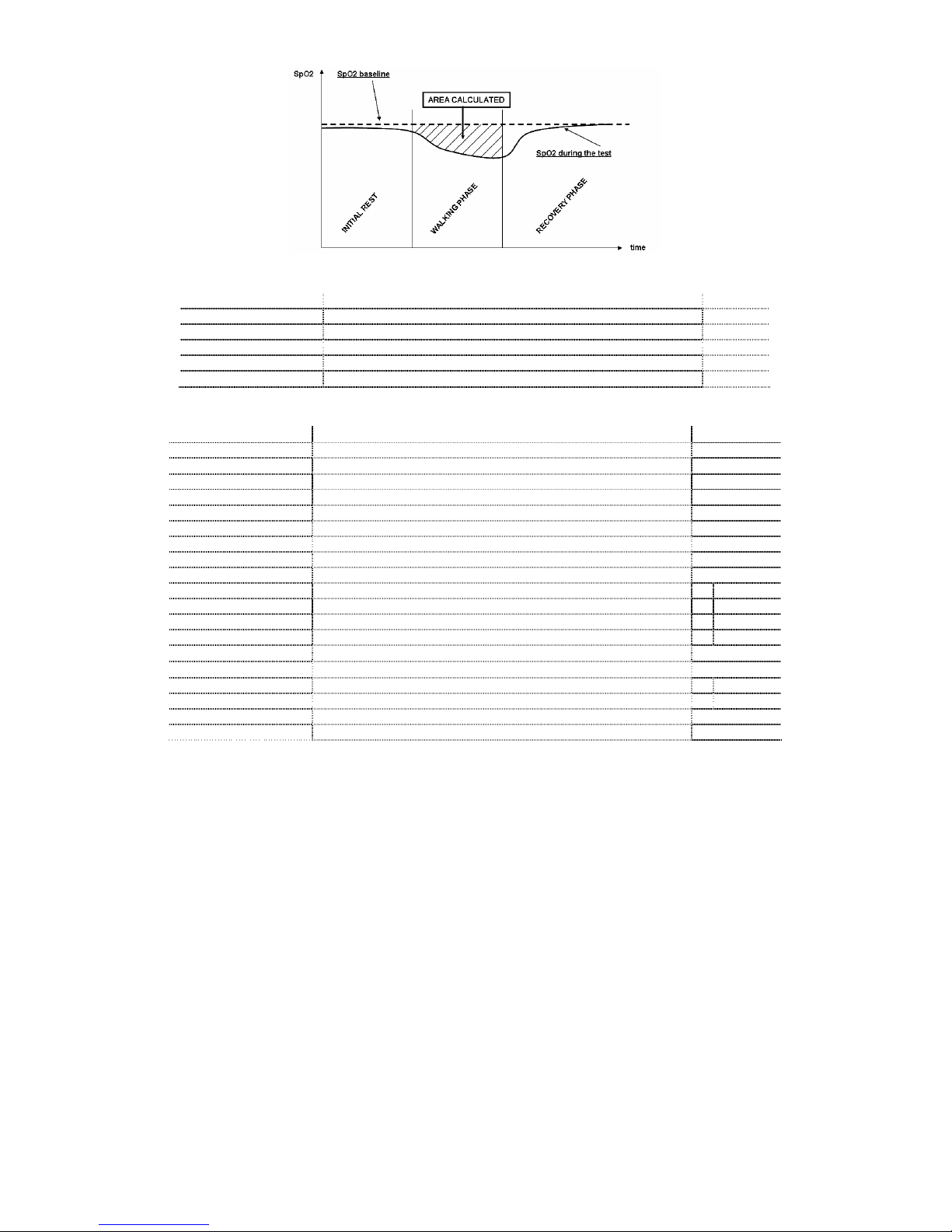
SpirolabIII – User’s Manual Code MIR 980067 REV 0 Page 15 / 47
Parameters required for walk test:
SYMBOL DESCRIPTION Units
Dyspnea Borg Baseline
Grade of dyspnea before walking \
Dyspnea Borg End Grade of dyspnea after walking \
Fatigue Borg Baseline Level of fatigue before walking \
Fatigue Borg End Level of fatigue after walking \
Walked Distance covered during walking m
Parameters measured with SpO2 Analysis:
SYMBOL DESCRIPTION Units
SpO2 Baseline SpO2 Average in first three minutes %
SpO2 Min SpO2 Minimum during analysis period %
SpO2 Max SpO2 Maximum during analysis period %
SpO2 Mean SpO2 Average during analysis period %
BPM Baseline Average pulse frequency in the first 3 minutes BPM
BPM Min Minimum pulse frequency during the analysis period BPM
BPM Max Maximum pulse frequency during the analysis period BPM
BPM Mean Average pulse frequency during the analysis period BPM
Recording time Total time measure of SpO2 hh:mm:ss
T < 90% Time passed with SpO2 < 90 % %
hh:mm:ss
T < 89% Time passed with SpO2 < 89 % %
hh:mm:ss
T < 88% Time passed with SpO2 < 88 % %
hh:mm:ss
T < 87% Time passed with SpO2 < 87 % %
hh:mm:ss
N°Events SpO2 < 89%
Fall of SpO2 below 89 % for at least 20 seconds \
∆Index [12s] Index of SpO2 fluctuation calculated in intervals of 12 seconds \
T< 40 BPM Time passed with pulse frequency < 40 BPM %
hh:mm:ss
T> 120 BPM Time passed with pulse frequency > 120 BPM %
hh:mm:ss
N°Events < 40 BPM Bradycardia events during the entire analysis period \
N°Events > 120 BPM Tachycardia events during the entire analysis period \
∆=DELTA
Acoustic signals for oximetry:
•Beep with frequency of the cardiac pulse
•Continuous beep in the case of either %SpO2or cardiac pulse going outside of the programmed alarm levels
•Continuous beep during oximetry measurement in the case of low battery level
The specifications for both the oximetry and for the cardiac pulse are the same, regardless of which of the above
mentioned oximetry sensors is used.
2 PRODUCT DESCRIPTION
SpirolabIII is a spirometer with an optional pulse oximetry module that facilitates the total valuation of lung function. It is
a powerful and compact measurement device intended for use by a physician (respiratory specialist), and which is
capable of calculating more than 30 spirometric parameters.
SpirolabIII is able to make FVC, VC, IVC, MVV and breathing profile tests, as well as the saturation of oxygen in the
blood and the heart beat.
It can operate in stand alone mode, and it can be connected to a PC or to a printer using any one of several available
methods: RS232, USB, Bluetooth.
It calculates an index of test acceptability (test quality control) and a measure of reproducibility; It also gives functional
interpretation with 11 possible levels following the latest ATS (American Thoracic Society) classification; it has an
internal memory sufficient for over 6000 spirometry tests or for 1000 hours (or 40 days) of oximetry monitoring.
The main spirometric parameters are measured and displayed and all data with Flow/Volume and Volume/time curves
can be printed out in seconds by the built-in thermal printer. The Flow/Volume curve is shown in real time on the display.
SpirolabIII – User’s Manual Code MIR 980067 REV 0 Page 16 / 47
Each test can be repeated as required. The best parameters are always available for quick viewing or printing. The
normal (predicted) values can be selected from five different authors. In general, within the European Union the ERS
(European Respiratory Society) predicted values are used.
The device also calculates the response to drug administration, i.e., the percentage change between spirometry results
obtained before and after the subject takes a drug) and the results of a bronchial challenge test or a bronchodilation
test. A comparison of data is made between POST (after-drug) and PRE (before drug administration).
The flow and volume measurement sensor is a digital turbine, based on the infrared interruption principal. This principal
ensures the accuracy and the reproducibility of the measurements without requiring a periodic calibration.
The main features of this kind of sensor are listed below:
•Accurate measurement even at very low flow rates (end of expiration)
•Not influenced by gas humidity nor density
•Shockproof and unbreakable
•Inexpensive to replace
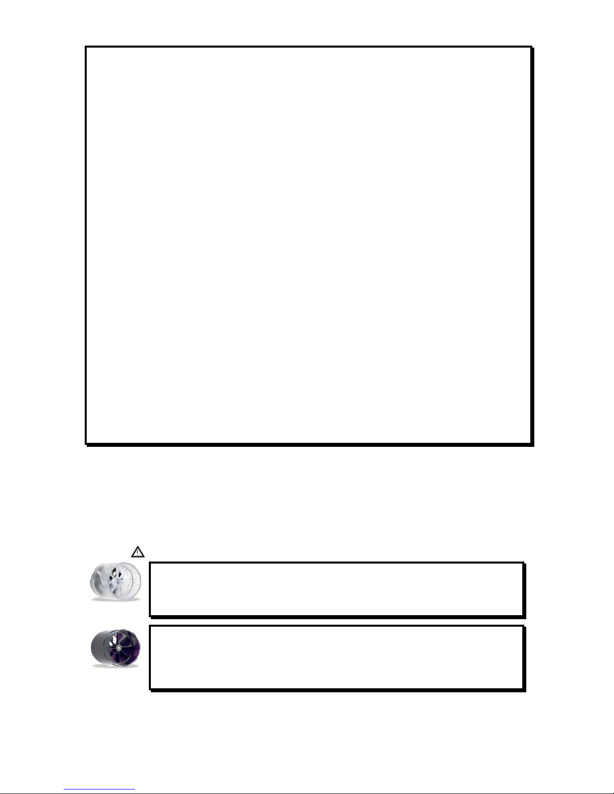
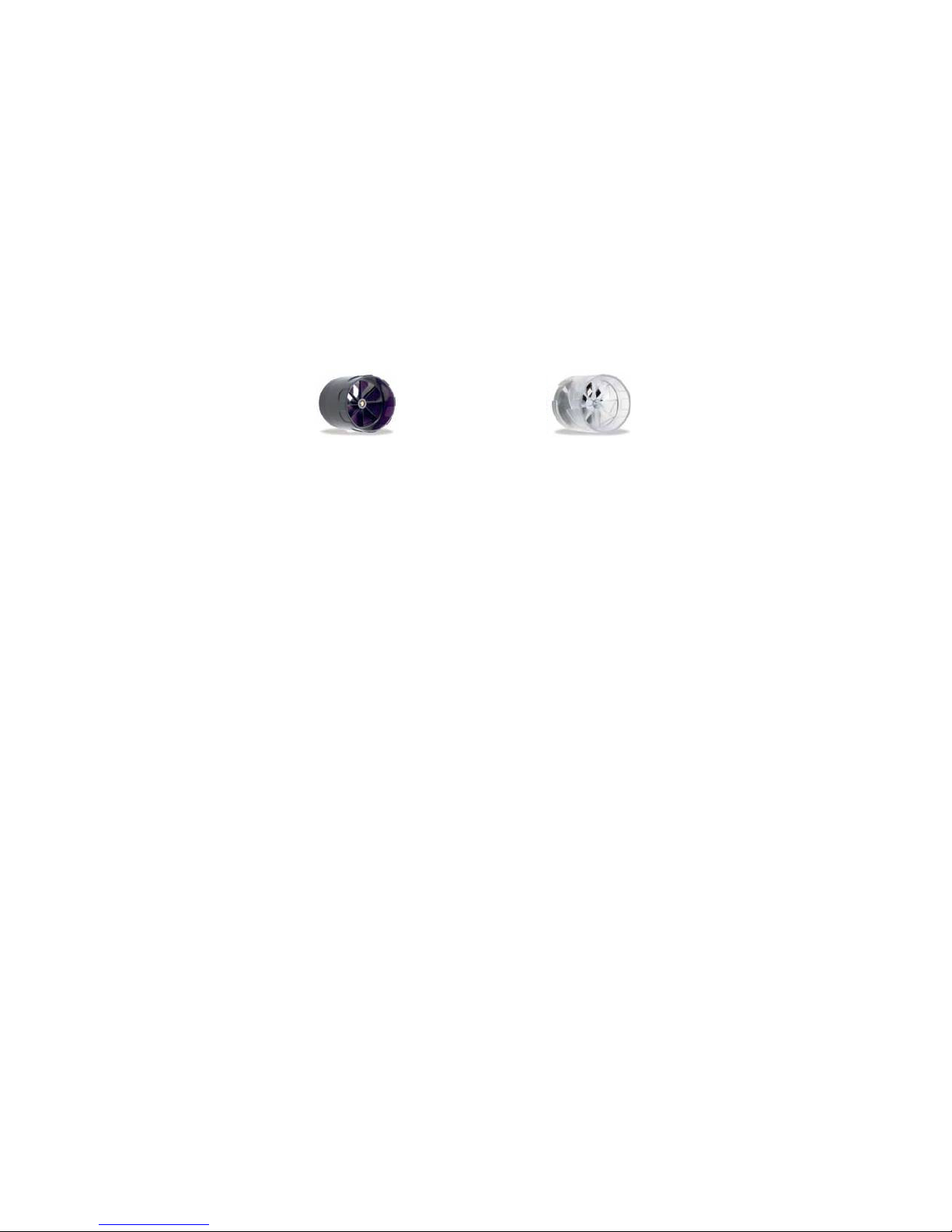
The turbine flow measurement sensor is available both in reusable and in single-patient disposable versions.
REUSABLE TURBINE
SINGLE-PATIENT DISPOSABLE
The following precautions must be observed to ensure that the characteristics of the turbine remain unaltered over time:
•For the disposable turbine: must always be substituted between patients.
•For the reusable turbine: always clean the turbine between patients, to ensure the maximum level of hygiene and
safety for the patient.
For a correct interpretation of a spirometry test, the measured values must be compared either with the so-called
normal or predicted values which are calculated from the anthropometric details of the patient or, alternatively, with the
personal best values from the clinical history of the subject.
The personal best values can vary considerably from the predicted values, which are taken from “healthy” subjects.
SpirolabIII is supplied with an RS-232 optoisolated serial communication port, which guarantees excellent electrical
protection (> 4 KV) both for the health care worker and for the subject, in compliance with the most strict European
safety standards (EN 60601-1).
The Bluetooth connection system can be used to connect the device directly to a printer (the Bluetooth system must be
installed and enabled on the printer as well).
SpirolabIII can also be connected to a PC (or to another computerised system) to configure the system. All spirometric
test results plus the related subject details stored inside the device can be transferred from the device to the PC and
then viewed within the winspiroPRO PC software (Flow/volume curves, spirometry parameters, plus optional oximetry
parameters).
The connection to the PC can be made in the following ways:
•through the RS232 port or
•through the USB port
The internal software (or firmware) of the device can be upgraded quickly and simply from a PC.
For upgrading the system consult the manufacturer or an authorized representative.
SpirolabIII gives an automatic interpretation of each spirometry test carried out, and assigns a “traffic light” feedback
(green, yellow or red) to each test or series of tests. The set up of the traffic light settings is made by the doctor
responsible for the system configuration.
Oximetry function
The oximetry sensor has two light emitting diodes (LEDs), one emits in the visible spectrum and one infrared. Both lights
then pass through the finger and are “read” by the receiver. As these lights pass through the finger, a proportion of the
light is absorbed by the blood and by the soft tissue, in function of the concentration of heamoglobin. The quantity of
light absorbed, at each frequency, depends on the degree of oxygenation of the haemoglobin inside the soft tissue.
This measurement principal ensures accuracy and reproducibility, without requiring regular calibration.
The oximetry sensor can be disinfected with isopropilic alcohol.
The operating battery is a 3.6V lithium battery.

SpirolabIII – User’s Manual Code MIR 980067 REV 0 Page 17 / 47
2.1 ILLUSTRATION OF SPIROLABIII
Thermal paper container
Flow sensor compartment
Display
Keyboard
Miniflowmeter sensor
Oximeter sensor
2.2 KEYBOARD
SYMBOL DESCRIPTION
On/Off
Adjust contrast, press several times as required
Adjust brightness, press several times as required
Advance the printer paper
Self-check key
Cancel the current operation
Select configuration menu
Correction key/cancel last data inserted
Information about options
View data in memory
Enter/modify patient data
View best test
View last test
View bronchodilation tests
Make POST test
Make oximetry test
Print
Make FVC test
Make VC test
Make MVV test
... Number keys
SpirolabIII – User’s Manual Code MIR 980067 REV 0 Page 18 / 47
Specifies female sex
Specifies male sex
Confirm last operation. This key is the ENTER key
Move cursor
2.3 CHARGING THE BATTERY
Make sure that the electrical information on the label of the charging unit corresponds to that of the power source.
Plug the power supply into an electrical outlet.
Plug the power supply jack into the socket on the back of the device.
Do not use the power supply if it is wet or damp.
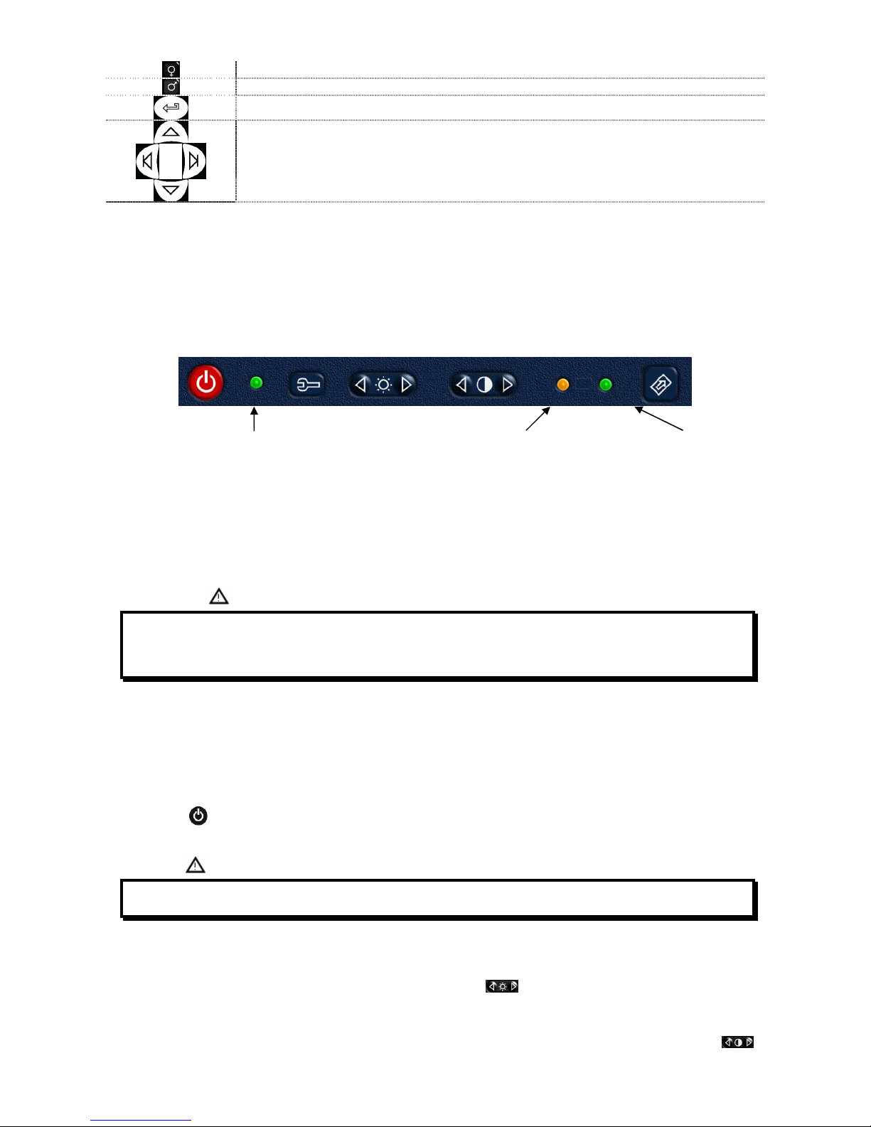
Green LED
POWER ON Orange LED
Battery charging Green LED
Battery charged
The charging process has several phrases which are indicated by two LEDs, green and orange (as shown above).
•Immediately after connecting the power supply, the orange LED starts to flash.
•After a few seconds the orange LED stops flashing and remains lit.
•For about 10 minutes the charging is partial while device automatically checks the battery condition.
•After about 10 minutes the charging starts and proceeds to a full charge.
•When charging is completed, the orange LED turns off and the green LED lights up.
' '
' * ' 1 7 9- :
%
2.4 SWITCHING ON THE SPIROMETER
First check that all the accessory items are in good condition.
Before using the device proceed with the cleaning and sterilizing operations, as described in the MAINTENANCE AND
CLEANING section.
Lift the LCD display, release the catch.
Press the red on/off key on the upper left corner of the keyboard. When the device is on, the green led on the right
hand side of the on/off key will light up.
< =( ! 3 ? ' ' '
2.5 SETTINGS
Backlight settings
To adjust the brightness of the display back light use the double key . Press several times as required, on the left
to diminish the brightness or on the right to increase it.
2.5.1 Contrast settings
To adjust the display contrast , to account for the angle of vision and the surrounding lighting, use the double key .
Press several times as required, on the left to diminish the contrast or on the right to increase it.
SpirolabIII – User’s Manual Code MIR 980067 REV 0 Page 19 / 47
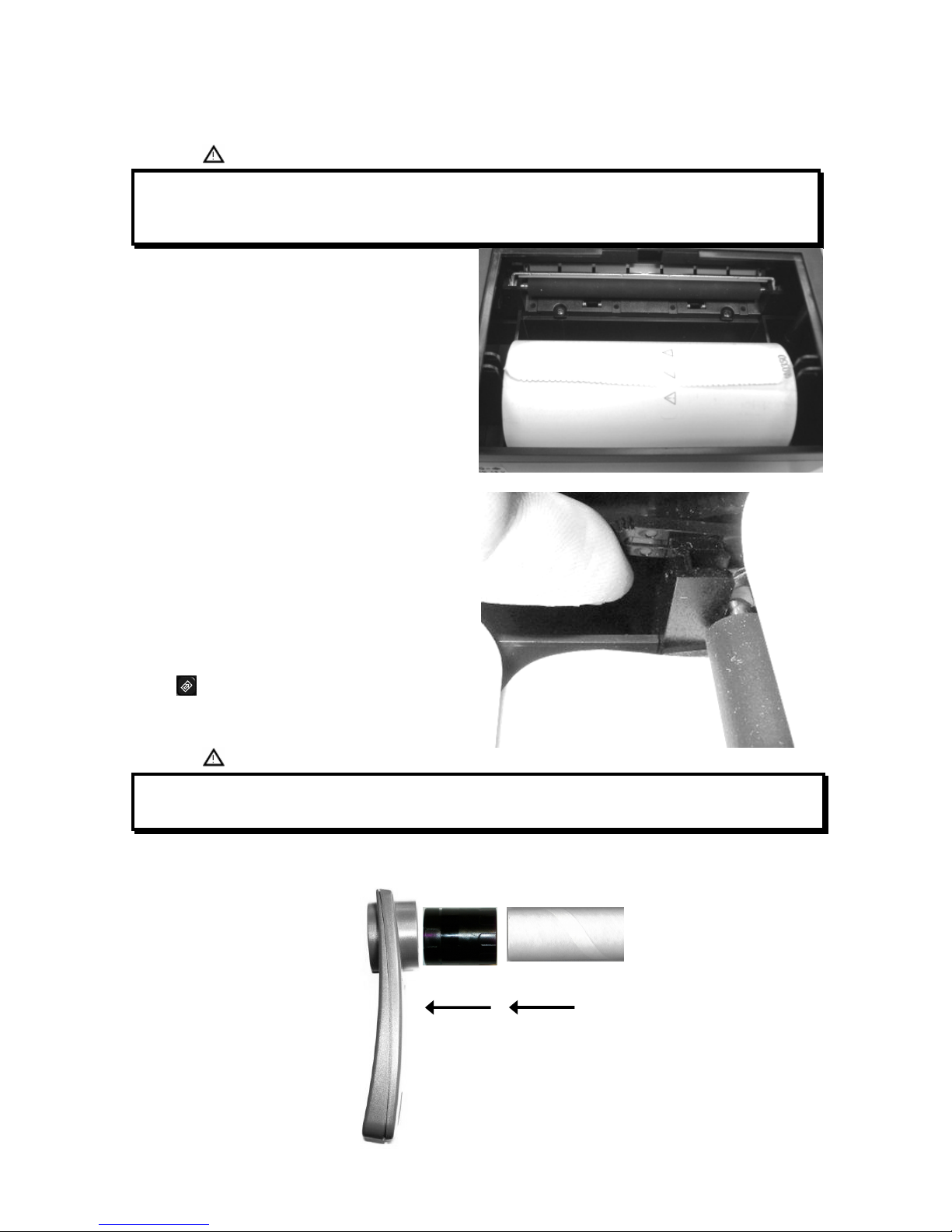
2.5.2 Loading the thermal paper
Open the lid of the thermal paper compartment and remove it from the device; remove the paper roll holder.
Insert the new roll of paper onto the paper roll holder.
'
6
Guide to the correct positioning of the paper roll holder
Push the paper into the slot located under the traction
reel (black rubber reel).
A sensor (as indicated in the image) detects the paper
and automatically advances it.
This image shows the position of the paper in relation to
the traction reel. The paper must advance through the slot
in the compartment when it is closed; close the lid of the
compartment.
If necessary make the paper advance manually by
pressing
& ' ..2 ' *
' E 7 &
2.5.3 Connecting the flow sensor
The flow sensor is made up of the elements shown in the following illustration.
Miniflowmeter Turbine Mouthpiece

SpirolabIII – User’s Manual Code MIR 980067 REV 0 Page 20 / 47
Before carrying out a spirometry test, verify that there are no foreign bodies present inside the flow sensor.
Connect the connection cable to the Miniflowmeter until hearing the ‘click’
which indicates that it has been correctly inserted. Connect the other end to
the SpirolabIII as shown in the image; again the ‘click’ will indicate the
correct insertion.
Make sure that a new disposable mouthpiece has been correctly inserted in
the turbine (mouthpiece holder).
8'
Remove the used mouthpiece and dispose of it after finishing the spirometry testing.
When the flow sensor head is not in use, we recommend that it is kept in its compartment.
Press lightly on the connector to detach the flow sensor turbine from the socket on the left hand side of the device and
proceed with the cleaning operations as outlined in the MAINTENANCE CLEANING section of the manual.
2.5.4 Switching off the spirometer
The device has an auto power-off system for reducing battery consumption. This feature can be set up from the menu by
selecting one of the following 3 options: 6, 60 or 240 minutes; the device will automatically switch off upon reaching the
pre-set time, when no activity has been made for that time.
If instead the device remains switched on when all operations are complete, switch it off manually by pressing .
When the device is switched off, the green (LED) indicator on the right hand side of the on/off key should also be off.
When the battery does not need charging then be sure to detach the power supply from the power supply socket on the
back of the device and remove the charger from the mains supply.
2.5.5 Initial settings
' '
SpirolabIII allows for the personalised setting of certain parameters through the Configuration Menu.
To access the menu, with the device switched on, press which contains the following list:
•Delete data in memory
•Print last calibration
•Turbine calibration
•Printout header text
•Change Date/Time
•Select language
•Select predicted values
•Setup printout
•Bluetooth setup
•Turbine
•Standard
•Date format
•Units format
•Auto power-off
Select the required option using or , until the symbol on the left of the screen is alongside your selection;
then press to access the option.
Use this key to recall the Configuration Menu, to set-up and/or to change certain main functions of the device.
Table of contents
Other Medical International Research Measuring Instrument manuals


Popular Measuring Instrument manuals by other brands


scigiene
scigiene CalCheck quick start guide

KBR
KBR multicount D5-3P-75A-MID quick guide

Fluid Components Intl
Fluid Components Intl AF Series Installation, operation and maintenance manual

Wohler
Wohler AMP2-16V Series user guide

Onicon
Onicon F-5100 Inline Installation and operation guide

ABB
ABB 10D1475 instruction manual