2-4
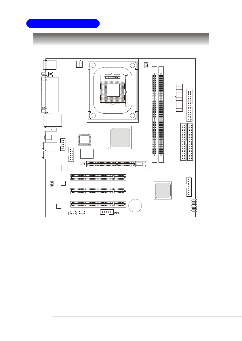
MS-6701 M-ATX Mainboard
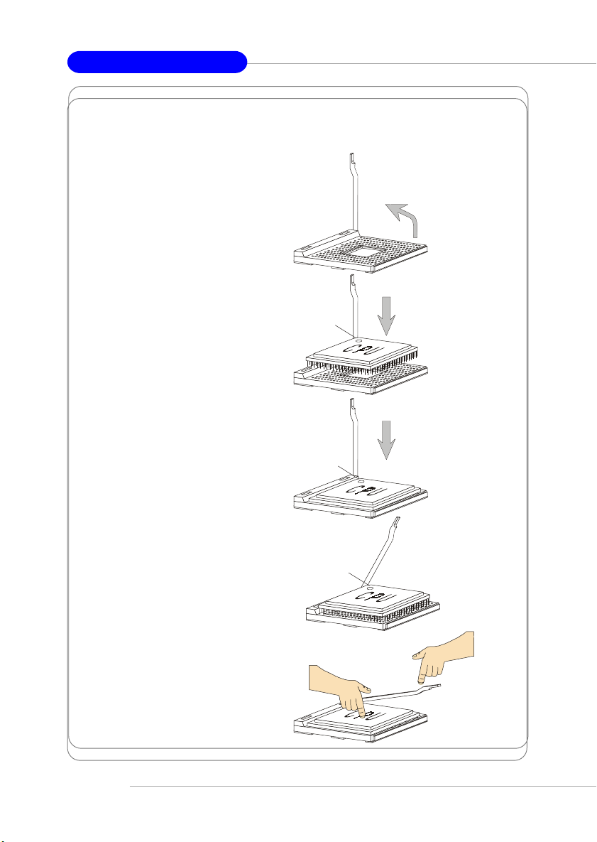
CPU Installation Procedures for Socket 478
1. Please turn off the power and
unplug the power cord before
installing the CPU.
2. Pull the lever sideways away
from the socket. Make sure
to raise the lever up to a 90-
degree angle.
3. Look for the gold arrow. The
gold arrow should point to-
wards the lever pivot. The
CPU can only fit in the correct
orientation.
4. If the CPU is correctly
installed, the pins should be
completely embedded into the
socket and can not be seen.
Please note that any violation
of the correct installation
procedures may cause
permanent damages to your
mainboard.
5. Press the CPU down firmly
into the socket and close the
lever. As the CPU is likely to
move while the lever is being
closed, always close the lever
with your fingers pressing
tightly on top of the CPU to
make sure the CPU is
properly and completely
embedded into the socket.
Open Lever
90 degree
Sliding
Plate
Close
Lever
Press down
the CPU
Gold arrow
Gold arrow
Gold arrow
Correct CPU placement
Incorrect CPU placement
X
O