MediterraneanTan HUSH SPRINTER User manual
DO NOT USE EQUIPMENT BEFORE READING THIS MANUAL
This manual contains important warnings and instructions.
Please read these instructions carefully and keep for your reference.
Please ll out the warranty card at the back to obtain warranty.
©2017 Mediterranean Tan Pty Ltd
Unit 5, 32 Essington Street, Grovedale, 3216, Australia.
email: [email protected]
International: +61 (3) 5245 8367
www.mtwb.com.au
DO NOT USE EQUIPMENT BEFORE READING THIS MANUAL
This manual contains important warnings and instructions.
Please read these instructions carefully and keep for your reference.
©2012 Solaire Pty Ltd
Ph: 1300 650 079 www.solaire.com.au
INSTRUCTION MANUAL
T
ANNING SYSTEM
(FOR PROFESSIONAL USE ONLY)
DO NOT USE EQUIPMENT BEFORE READING THIS MANUAL
HUSH endura
TM
SPRINTER
(Suitable for up to 100 sprays per day)
Non-continuous use - up to 30 minutes use
The Hush Sprinter™ sound level is: 80db
™
DO NOT USE EQUIPMENT BEFORE READING THIS MANUAL
This manual contains important warnings and instructions.
Please read these instructions carefully and keep for your reference.
©2012 Solaire Pty Ltd
Ph: 1300 650 079 www.solaire.com.au
INSTRUCTION MANUAL
TANNING SYSTEM
(FOR PROFESSIONAL USE ONLY)
DO NOT USE EQUIPMENT BEFORE READING THIS MANUAL
1

Table of Contents
1. General Safety Information: ........................................................................................................ 4
2. Set up and operate your Hush Sprinter™Spray Tan System: ................................................. 5
3. Prepare the Hush Optimiser™Spray Gun .................................................................................... 6
4. Adjusting the Hush Optimiser™Spray Gun ................................................................................. 9
5. Spraying ....................................................................................................................................... 10
6. Maintenance ................................................................................................................................. 11
7. Troubleshooting ........................................................................................................................... 13
8. Warranty Card............................................................................................................................... 17
2

FEATURES
• Designed to perform, think a lot of tans in a week.
• Motor, pre-set for Spray Tanning delivers superior airow.
• Commercial Grade Exterior Casing - easy cleaning.
• Heavy-duty rubber feet to protect oors
• 3.5 Meters lightweight, tough exible hose
• Brass quick-connections to Machine and Gun
• Easy to ll, simply place gun on the holder and ll the cup 3/4 full. The miniature gravity cup holds 250ml
• Carry Handle
• Stainless steel 0.5 mm ne needle tip
• Only 8kg with gun, 7kg without
• 37cm Long x 25cm High x 24cm Wide
• Metal Connections\
• 80 dB
• 12 MONTH WARRANTY
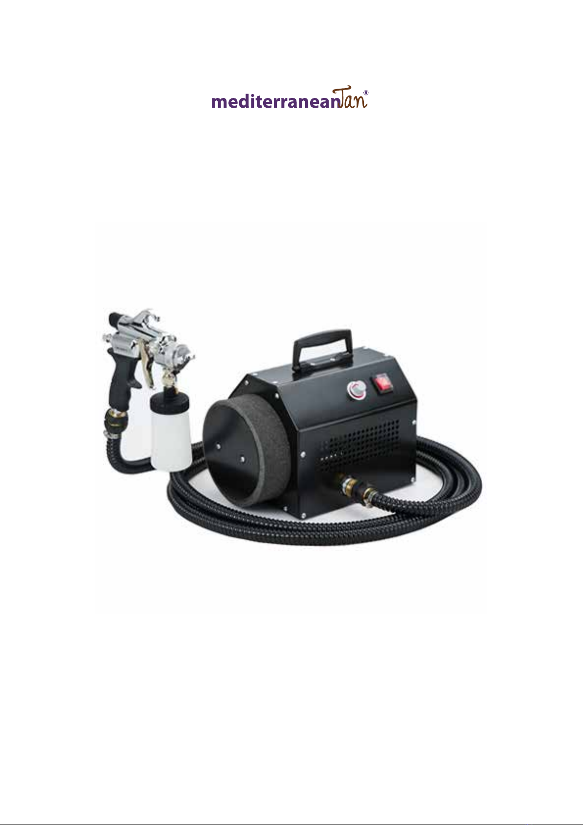
The Hush Sprinter™ By MediterraneanTan® provides a superior performance delivering a awless tan through a powerful
yet whisper quiet motor. The name says is all - Sprinter™ - when performance is required.
HUSH SPRINTER™BY MEDITERRANEANTAN®INSTRUCTION
MANUAL
Congratulations on purchasing the Hush Sprinter™ tanning system. This product has been specially designed to provide
the best application of professional spray tanning solutions.
Take a minute to read and understand how to operate your new Hush Sprinter™ tanning system and you will be able to
provide the perfect tan with every application.
Your Hush Sprinter™ is packaged with the following:
1. Hush Sprinter™ unit.
2. 3.5m lightweight, tough Flexible Hose
3. Hush Optimiser™ Spray Gun
4. Instruction Manual (see website)
5. Warranty Card
HUSH endura
SPRINTER™
3

HUSH endura
™
SPRINTER
1. General Safety Information
Read all instructions and safety precautions before operating the unit.
THIS INDICATES A CONDITION THAT WILL CAUSE SERIOUS INJURY OR LOSS OF LIFE IF THE WARNING IS IGNORED.
THIS INDICATES A CONDITION THAT COULD CAUSE SERIOUS INJURY OR LOSS OF LIFE IF THE WARNING IS IGNORED.
THIS INDICATES A CONDITION THAT MAY CAUSE MINOR INJURY AND/OR EQUIPMENT/PROPERTY DAMAGE.
GROUNDING INSTRUCTIONS
This product must be properly grounded. In the event of an electrical short circuit, grounding reduces the risk of electrical shock by
providing an alternate path for the electrical current.
This product is equipped with a cord that has a ground wire and an appropriate ground plug. Plug the unit into an outlet that is properly
installed and grounded in accordance with local codes and ordinances.
I
IMPROPER INSTALLATION OF THE GROUND PLUG CAN RESULT IN THE RISK OF
ELECTRICAL SHOCK. IF REPAIR OR REPLACEMENT OF THE PLUG OR CORD IS
NECESSARY, DO NOT CONNECT THE GROUND WIRE TO EITHER FLAT BLADE
TERMINAL. THE WIRE WITH GREEN INSULATION (WITH OR WITHOUT A YELLOW
STRIPE) IS THE GROUNDING WIRE.
1. For any question regarding proper installation of the ground plug, consult a qualied
(licensed or certied) electrician.
2. Do not modify the plug provided. If the plug does not t the outlet, have the proper
outlet installed by a qualied electrician.
3. This product is for use on a nominal 240-volt circuit and has a grounding plug that
looks like the plug in Figure 2. Make sure that the product is connected to an outlet
having the same conguration as the plug. No adapters should be used with this
product.
4. If an extension cord is required, use only a three wire extension cord that has the
same conguration as the unit cord, including the ground terminal. Make
sure that the extension cord is plugged into a properly grounded receptacle.
5. When using an extension cord, be sure it is in good condition and meets specications.
6. Ensure the Hush Sprinter™ is tagged and tested every 12 months after initial purchase to comply with Australian Electrical Safety
standards.
7. Always turn off power switch of Hush Sprinter™ and remove plug after operation.
8. Be aware to hold the solid plug body to remove from socket. Never remove the plug by just pulling the exible part of the power
cord
9. Disassemble or maintenance of the Hush Sprinter™ is to be conducted by an authorised technician only as this voids all warranty.
10. Do not operate near water or moisture as electrocution may occur.
3
1 General Safety Information:
Read all instructions and safety precautions before operating the unit.
THIS INDICATES A CONDITION THAT WILL CAUSE SERIOUS INJURY OR LOSS OF LIFE IF THE WARNING IS
IGNORED.
THIS INDICATES A CONDITION THAT COULD CAUSE SERIOUS INJURY OR LOSS OF LIFE IF THE WARNING IS
IGNORED.
THIS INDICATES A CONDITION THAT MAY CAUSE MINOR INJURY AND/OR
EQUIPMENT/PROPERTY DAMAGE.
• Risk of fire or explosion! Solvent and paint fumes can explode or ignite, causing severe
injury and property damage.
• Paints and solvents containing HALOGENATED HYDROCARBONS can react explosively
with aluminum. Always check the product’s label before using these materials in the unit.
• Hazardous vapors: Paint, solvents, insecticides and other materials may be harmful if
inhaled, causing severe nausea, fainting or poisoning.
• Make sure the room is well ventilated. Avoid all ignition sources, such as static electricity
sparks, open flames, hot objects, sparks from connecting and disconnecting power cords,
and working light switches.
• Follow the material and solvent manufacturers’ safety precautions and warnings. Do not
use liquids with flash points less than 100 degrees Fahrenheit (38 degrees Celsius).
• Static electricity can be produced by HVLP spraying. Make sure any electrically conductive
object being sprayed is grounded to prevent static sparking. The sprayer is grounded to
prevent static sparking. The spray grounded through the electrical cord. If an extension
cord is necessary, the cord must be a grounded with three wires made for the appropriate
voltage used.
• Use a respirator or mask whenever there is a chance that vapors may be inhaled. Read
all instructions with the mask to ensure that the mask will provide the necessary
protection against the inhalation of harmful vapors.
• Do not carry the turbine while spraying.
• Keep the turbine at the maximum distance from the spraying area.
4
1 General Safety Information cont’d.:
• Tipping the Spray Gun causes the Spray Gun to clog. Dried spray material also clogs the pressure delivery tube
and fittings. The Spray Gun does not function when clogging occurs.
• When not in use, be sure to disconnect the hose and place the Spray Gun into the holder in the turbine to avoid
tipping.
GROUNDING INSTRUCTIONS
This product must be properly grounded. In the event of an electrical short circuit, grounding reduces the risk of electrical
shock by providing an alternate path for the electrical current.
This product is equipped with a cord that has a ground wire and an appropriate ground plug. Plug the unit into an outlet
that is properly installed and grounded in accordance with local codes and ordinances.
IMPROPER INSTALLATION OF THE GROUND PLUG CAN RESULT IN THE RISK OF
ELECTRICAL SHOCK. IF REPAIR OR REPLACEMENT OF THE PLUG OR CORD IS
NECESSARY, DO NOT CONNECT THE GROUND WIRE TO EITHER FLAT BLADE TERMINAL.
THE WIRE WITH GREEN INSULATION (WITH OR WITHOUT A YELLOW STRIPE) IS THE
GROUNDING WIRE.
1. For any question regarding proper installation of the ground plug, consult a qualified
(licensed or certified) electrician.
2. Do not modify the plug provided. If the plug does not fit the outlet, have the proper
outlet installed by a qualified electrician.
3. This product is for use on a nominal 240-volt circuit and has a grounding plug that
looks like the plug in Figure 2. Make sure that the product is connected to an outlet
having the same configuration as the plug. No adapters should be used with this
product.
4. If an extension cord is required, use only a three wire extension cord that has the
same configuration as the unit cord, including the (round) ground terminal. Make
sure that the extension cord is plugged into a properly grounded receptacle.
5. When using an extension cord, be sure it is in good condition and heavy enough to
meet the specifications in the chart below. If an extension cord is needed the
following wire sizes must be used.
6. (See Chart 1) Figure 2
25’ cord……………………..…….10, 12, or 14 Gauge
50’ cord……………………….………..10 or 12 Gauge
100’ cord………………………………………10 Gauge
Chart 1 Extension Cord Requirements
Fig 1
Fig 2
4
HUSH endura
™
SPRINTER
2. Set up and operate your Hush Sprinter™Tanning System
1. Plug the Hush Sprinter™ tanning system unit into a proper electrical outlet. Make sure that the electric current you are
connecting to is the same as your unit. (240v). DO NOT attempt to connect the unit to the wrong electric current as this
will not only damage your unit but also void your warranty.
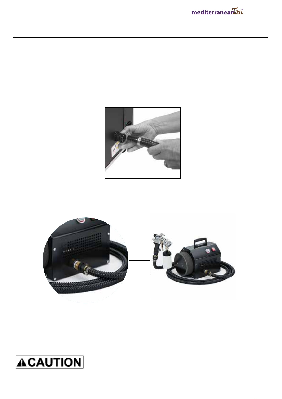
2. Next, locate the male end of the air hose and connect it to the female quick connect on the Hush Sprinter™ tanning
system.
a. To insert the male connection pull back on the ring of the black coupler located on the Hush Sprinter™
tanning system and insert the male connector on the hose. Figure 6.
Fig. 6
b. Release the ring to allow the coupler to snap into place. The hose should now be connected to the unit
Figure 7.
Fig. 7
c. To remove the air hose, pull back on the ring of the black coupler and remove
d. See page 7 for How to connect the Hush Sprinter™ to the Hush Optimiser™ spray gun.
To Turn the UNIT ON
Press the red power switch button and use the variable control to set your airow pressure.
Ifyouhavejustnishedspraying,theconnectormaybehot.AllowtheHush Sprinter™unittocooldownforabout
10 minutes before disconnecting the air hose from the Hush Sprinter™unit. Use Caution!
5
2 Set up and operate your PRINCESS Tanning System:
1. Plug the PRINCESS tanning system unit into a proper electrical outlet. Make sure that the electric current
you are connecting to is the same as your unit. (110v or 220v). DO NOT attempt to connect the unit to the wrong
electric current as this will not only damage your unit but also void your warranty.
2. Next, locate the male end of the air hose and connect it to the female quick connect on the PRINCESS
tanning system.
a. To insert the coupler pull back on the ring of the black coupler located on the PRINCESS tanning
system and connect it to the male connector on the hose. Figure 6.
Fig. 6
b. Release the ring to allow the coupler to snap into place. The hose should now be connected to the
unit Figure 7.
Fig. 7
c. To remove the air hose, pull back on the ring of the black coupler and remove
If you have just finished spraying, the connector may be hot. Allow the PRINCESS unit to cool down
or about 10 minutes before disconnecting the air hose from the turbo unit. Use Caution!
5

HUSH endura
™
SPRINTER
3 Prepare the Hush Optimiser™Spray Gun:
6

HUSH endura
™
SPRINTER
3 Prepare the Hush Optimiser™Spray Gun cont’d
1. Follow the diagram to prepare the Hush Optimiser™ Spray Gun
a. Unscrew the plastic cup from the Hush Optimiser™ Spray Gun. Pour tanning solution into the cup. Do not ll more
than ¾ full.
b. Carefully screw the cup back onto the main body of the Hush Optimiser™ Spray Gun. Screw the cup on rmly but
DO NOT over tighten. Over tightening will cause the cup to “pop” and damage the threads. Leakage can
then occur requiring replacement of the cup.
c. Locate the air cap (#1) on the Hush Optimiser™ diagram. With the gun facing towards you, slightly turn the air cap
ring (#1-1, page 6) anti clockwise to loosen the air cap. Notice that you can now rotate the air cap freely.
d. Look at Mist Applicator Patterns diagram above. Note the position of the air cap and the direction of the spray
pattern. Pattern 1 is for spraying across from side to side. Pattern 2 is for spraying up and down. Patterns 1 and 2 are
the most common positions for applying tanning solutions.
5
2 Set up and operate your PRINCESS Tanning System:
1. Plug the PRINCESS tanning system unit into a proper electrical outlet. Make sure that the electric current
you are connecting to is the same as your unit. (110v or 220v). DO NOT attempt to connect the unit to the wrong
electric current as this will not only damage your unit but also void your warranty.
2. Next, locate the male end of the air hose and connect it to the female quick connect on the PRINCESS
tanning system.
a. To insert the coupler pull back on the ring of the black coupler located on the PRINCESS tanning
system and connect it to the male connector on the hose. Figure 6.
Fig. 6
b. Release the ring to allow the coupler to snap into place. The hose should now be connected to the
unit Figure 7.
Fig. 7
c. To remove the air hose, pull back on the ring of the black coupler and remove
If you have just finished spraying, the connector may be hot. Allow the PRINCESS unit to cool down
or about 10 minutes before disconnecting the air hose from the turbo unit. Use Caution!
7

HUSH endura
™
SPRINTER
3. Prepare the Hush Optimiser™Spray Gun cont’d
e. Turn the air cap (#1) to the position you want. Again with the gun facing towards you, turn the air cap ring (#1-1, page
6) clockwise to lock the air cap in place.
f. The spray pattern can be changed from at to circle using the Pattern Adjusting knob (#12). A circle pattern (as seen
below) can be used for contouring.
2. Next, position the Hush Sprinter™ unit as far away as practical and possible from the area where you will be spraying.
3. Attach the remaining end of the hose to the Hush Optimiser™ Spray Gun as follows:
a. Locate the male connection at the bottom of the Hush Optimiser™ Spray Gun. See gure 8.
b. Pull back on the coupler of the brass connector on the air hose.
Fig 8
←FlowSolutionScrew
←Pattern Adjusting Knob
How to mist in a spot or circle
8

HUSH endura
™
SPRINTER
4. Adjusting the Hush Optimiser™Spray Gun
1. Locate the Solution Flow Screw (#22, page 7) on the Hush Optimiser™ diagram.
2. Face the front of the Hush Optimiser™ gun away from you and turn the Solution Flow Screw clockwise. This reduces
and will eventually stop the ow of solution. DO NOT over-tighten the screw as this will cause damage to the end of
the needle. Once the trigger cannot be pulled back there is no point in tightening the screw down more, this will only
damage the end of the needle.
3. Turning the Solution Flow Screw anti clockwise will increase the ow of solution and turning the solution ow screw
clockwise will decrease the ow of solution.
4. In general, 1 ½ - 2 full turns from the fully closed position will provide a good solution ow. You may nd that you want
more or less solution. You can adjust the Solution Flow Screw to your desired setting. NOTE: Opening the Solution
Flow Screw more than 3 turns will not increase the solution ow and will in fact decrease the efciency of your Hush
Optimiser™ Spray Gun.
5. In general, hold the Hush Optimiser™ Spray Gun 20-30cm from the person being sprayed. Moving the Hush
Optimiser™ Spray Gun back will increase the size of the mist pattern. Moving the Hush Optimiser™ Spray Gun closer
will decrease the size of the mist pattern. The further away you hold the Hush Optimiser™ Spray Gun, the more you will
need to increase the solution ow thus causing abnormal amounts of airborne solution (overspray).
6. Holding the Hush Optimiser™ Spray Gun closer to the person being sprayed along with a minimum ow of solution will
provide the best results, no streaks or running solution and virtually no mist in the spray area.
7. Be sure to move the Hush Optimiser™ Spray Gun at a slow, steady speed keeping the distance of the Spray Gun the
same throughout the application. This will ensure perfect results. It is actually very easy. Practice, Practice, Practice.
8. It is best to hold the Hush Optimiser™ Spray Gun in a vertical position when spraying. If you want to change the
direction of the mist pattern, rotate the position of the air cap rather than turning the Hush Optimiser™ Spray Gun on its
side. Refer to the spray gun pattern diagram on page 7/8.
9. Always hold or store the Hush Optimiser™ Spray Gun in a vertical position. It is a good habit to use, when you are not
spraying.
10. Do not over-tighten the solution ow screw (#22, page 7) as this will damage the end of the needle point. Tighten the
screw until the needle cannot be pulled back. Once this point is reached there is no point in turning the solution slow
screw anymore as this will only cause damage to the needle point.
5
2 Set up and operate your PRINCESS Tanning System:
1. Plug the PRINCESS tanning system unit into a proper electrical outlet. Make sure that the electric current
you are connecting to is the same as your unit. (110v or 220v). DO NOT attempt to connect the unit to the wrong
electric current as this will not only damage your unit but also void your warranty.
2. Next, locate the male end of the air hose and connect it to the female quick connect on the PRINCESS
tanning system.
a. To insert the coupler pull back on the ring of the black coupler located on the PRINCESS tanning
system and connect it to the male connector on the hose. Figure 6.
Fig. 6
b. Release the ring to allow the coupler to snap into place. The hose should now be connected to the
unit Figure 7.
Fig. 7
c. To remove the air hose, pull back on the ring of the black coupler and remove
If you have just finished spraying, the connector may be hot. Allow the PRINCESS unit to cool down
or about 10 minutes before disconnecting the air hose from the turbo unit. Use Caution!
9

HUSH endura
™
SPRINTER
5. Spraying
You should now be ready to spray your client. Good quality results with your Hush Sprinter™ spray tanning system are a
combination of careful preparation of your client, a proper spraying environment, a basic knowledge of the solution you will
be using and how these solutions work with your Hush Sprinter™ spray tanning system.
1. You are now ready to begin spraying.
2. The ON/OFF Switch is located at the side of the Hush Sprinter™ Unit. Turn it on. You will hear a sound similar to a
vacuum cleaner. You may also notice that air is now blowing out of the front of the Hush Sprinter™ Spray Gun. This is
correct. Air will continually ow from the air cap of the Hush Sprinter™ Spray Gun as long as the Hush Sprinter™ Unit is
running and the air hose is connected.
3. Your Hush Sprinter™ motor unit is set for the perfect atomisation of spray tan solution.
4. Open the Solution Flow Screw as described in item 4 and set the Pattern Adjustment Knob.
5. Set the mist pattern you wish to use by adjusting the air cap to the desired position. Refer to the spray gun pattern
diagram on page 7/8.
6. Direct the Hush Optimiser™ Spray Gun to the area of the body that you want to start spraying.
7. Pull back on the trigger (#32, Diagram on page 7) and move the Hush Optimiser™ Spray Gun as noted in the diagram
below. Do not wave the Spray Gun back and forth in front of your client by bending your wrist. Rather, keep your wrist
straight and move your entire arm. Movement should be steady, even and deliberate, keeping your distance the same at
all times.
9
5 Spraying/Misting
a. You are now ready to begin misting.
b. The ON/OFF Switch is located under the carry handle of the Turbo Unit. Turn it on. You will hear a
sound similar to a vacuum cleaner. You may also notice that air is now blowing out of the front of the
Spray Gun. This is correct. Air will continually flow from the air cap of the Spray Gun as long as the
Turbo Unit is running and the air hose is connected.
c. Open the Solution Flow Screw as described in item 4.
d. Set the mist pattern you wish to use by adjusting the air cap to the desired position. Refer to Mist
Pattern Diagram.
e. Direct the Spray Gun to the area of the body that you want to start spraying.
f. Pull back on the trigger (#13) and move the Spray Gun as noted in the diagram below. Do not wave the
Spray Gun back and forth in front of your client by bending your wrist. Rather, keep your wrist straight
and move your entire arm. Movement should be steady, even and deliberate, keeping your distance the
same at all times.
PROPER MISTING TECHNIQUE
10

HUSH endura
™
SPRINTER
6. Maintenance
1. Hush Sprinter™Unit.
a. There is minimal maintenance to perform on the Hush Sprinter™ unit. Make sure you keep the motor unit as far
away from your spraying area as possible.
b. Every night wipe over Hush Sprinter™ unit with a damp cloth.
PleaseNote:Ensurenoexcesswaterisusedasthiswillshortcircuittheunit.
c. Please see maintenance cleaning video at: http://www.mtwb.com.au/Main.asp?_=Sunless Education
2. Air Filter.
a. Remove the air lter at the base of the unit and wash at the end of every week under hot soapy water. Ensure it is
dry before replacing it. Replace the white lter when it can’t be washed anymore.
3. Air Hose.
a. Wipe the air hose daily with a damp cloth and store in a clean dry place.
4. Hush Optimiser™Spray Gun - Daily Clean.
a. It is important to clean your Hush Optimiser™Spray Gun daily.
b. At the end of the day or when the equipment will not be used any more, disconnect the Hush Optimiser™Spray Gun
from the air hose.
c. Carefully unscrew the cup. If there is remaining solution, either close the cup with a lid, or pour the remaining
solution into a proper storage container.
d. Rinse the cup under hot running water until clean.
e. Turn the gun upside down and allow hot running water to run into the plastic tube, pull back the trigger and allow the
water to ow out of the nozzle. Continue until clear.
f. Fill the cup about ¼ full with AIRBRUSH CLEANER. Reconnect the Hush Optimiser™Spray Gun to Air Hose.
Turn on the Hush Sprinter™ Unit. Direct the Hush Optimiser™ Spray Gun to a safe area and spray the AIRBRUSH
CLEANER through the Hush Optimiser™ Spray Gun until the cup is empty and until the Spray becomes CLEAR.
g. Turn off the Hush Sprinter™ Unit. Disconnect the Hush Optimiser™Spray Gun. Unscrew the cup.
h. Start to dismantle your Hush Optimiser™Spray Gun.
i. Unscrew and remove the Air Cap Ring (#1, Diagram on page 7). Rinse the threads under warm running water. Wipe,
the threads and dry. Add a small amount of Spray lube or Vaseline to the threads.
j. Reinstall the two pieces you just removed by reversing the removal procedure. Your Hush Optimiser™Spray Gun
should be ready for the next use.
j. Please see Spray Gun maintenance cleaning video at: http://www.mtwb.com.au/Main.asp?_=Sunless Education
11
HUSH endura
™
SPRINTER
6. Maintenance Cont’d
5. Hush Optimiser™Spray Gun - Weekly Clean.
Perform the Daily procedure then continue:
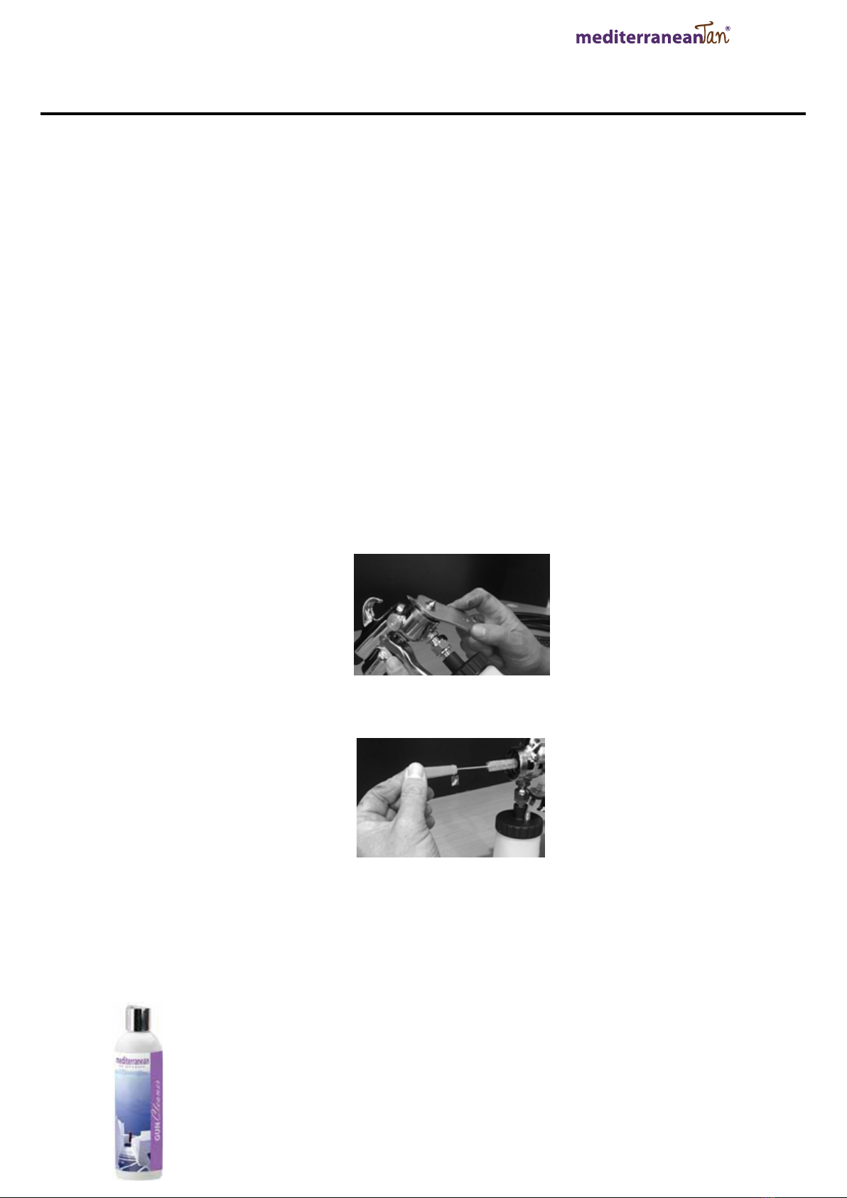
a. The Solution needle (#20, Diagram on page 6) To remove: Face the front of the gun away from you, turn the
Solution ow screw anti clockwise until it comes out of the Spray Gun. Be careful when removing the solution ow
Screw as there is a small spring (#21, Diagram on page 6) around the needle. Do not loose it. This is important to
the operation of the Hush Optmiser™ Spray Gun. Set the spring aside and pull the trigger all the way back until you
can grab the needle with your nger tips and pull it out from the back of the Hush Optimiser™Spray Gun. Once
removed, rinse under the hot running water, dip into AIRBRUSH CLEANER and dry. Add gun lubrication or vaseline
to the needle. Simply rub a small amount of Spray Gun lube or vaseline around the needle shaft and spring. Later to
reinstall repeat these steps in reverse.
b. The solution nozzle (#2, Diagram on page 6) can be removed for additional cleaning as it is recommended to, the
needle must rst be removed to do this procedure. With an adjustable wrench or spanner that is supplied when
you purchase the unit, place the tip of your adjustable wrench or spanner on the nut of the nozzle (whilst the gun is
facing you) and twist anti clockwise. Be careful.
Rinse under hot running water, take a cotton bud or the brush supplied and dip it into gun cleaner and clean inside
the threads. DO NOT USE ANYTHING METAL as it will scratch the threads or nozzle and this will cause leaking. To
reinstall repeat these steps in reverse.
c. Please see Spray Gun maintenance cleaning video at: http://www.mtwb.com.au/Main.asp?_=Sunless Education
HVLP Gun/Airbrush Cleaner:
Specially formulated to breakdown and remove spray tanning ingredients and residue from Airbrush/HVLP tips & nozzles.
When using spray tan in your Hush Optimiser™ spray gun it can leave a build-up of residue that,
overtime, can clog your Hush Optimiser™spray gun tip and interfere with the effectiveness of
your spray pattern. Mediterranean Tan’s Airbrush Cleaner is specically developed to breakdown
the residue left in your airbrush tip or spray gun nozzle. Spray Tan Gun Cleaner
Available through our Ofce – please call us!
*Excluded any parts that may be required to be replaced.
12

HUSH endura
™
SPRINTER
7. Troubleshooting
Q. Hush Sprinter™ unit turned ON. Air blows out of Hush Optimiser™ Spray Gun?
• This is correct. Air blows constantly when Hush Sprinter™ unit is ON.
Q. Hush Sprinter™ unit turned ON. Unit does not operate or blow air?
• Check that the unit is plugged in to proper electric source. Be sure there is power at the electric source. Check if the unit
has been running. The overheat protector will be activated if the unit has reached 125ºC. Allow the unit to cool if overheating.
Q. Hush Sprinter™ unit is turned ON the trigger is pulled back on Hush Optimiser™ Spray Gun but no solution comes out?
• Check that the cup is screwed rmly to Hush Optimiser™ Spray Gun.
• Check that there is no solution bubbling or leaking around the cup.
• Turn Hush Sprinter™ unit OFF. Unscrew cup. Be sure that Solution Tube (#39, Diagram on page 7) is connected and has
not come loose.
• Turn Hush Sprinter™ unit OFF. Remove air cap ring (#1-1, Diagram on page 6) remove air cap (#1-2, Diagram on page 6)
remove the needle (#20, Diagram on page 6) remove nozzle (#2, Diagram on page 6) with an adjustable wrench or spanner
which is supplied at purchase. Rinse Solution Nozzle under running water and check for dried solution that may have
blocked the hole. Reinstall Solution Nozzle, solution needle, air cap and air cap ring. Try spraying again.
Q. Solution leaks in front of trigger?
• With an adjustable wrench or spanner tighten Solution Needle Packing Screw (#28, Diagram on page 6). Do not
over tighten. This can cause Solution needle to stick and not spring back. Try spraying again. If leaking continues the
Solution Needle Packing needs to be replaced. (Rare). Remove solution needle (#20, Diagram on page 6), then remove
Solution Needle Packing Screw (#28, Diagram on page 6). Dry out the Solution Needle Packing’s Replace. Reinstall
Solution Needle Packing Screw and solution needle. Tighten all the way, and then back off slightly. (1/8 turn) Test the Hush
Optimiser™ spray gun for leakage.
Q. When Hush Sprinter™ unit is ON, Solution continues to spray from the Hush Optimiser™ Spray Gun without trigger being
pulled?
• Immediately turn Hush Sprinter™ unit OFF.
• Disconnect Hush Optimiser™ spray gun from air hose.
• Slightly adjust (loosen) Solution Needle Packing Screw (#28, Diagram on page 6). Test to see if problem is resolved.
• Check to see that Needle Spring is installed. (#21, Diagram on page 6). Remove Solution Flow Screw (#22, Diagram on
page 6). Look for Needle Spring around the back of the Solution Needle. If lost, order for replacement.
• Check Solution nozzle. Remove and clean following the spray gun weekly clean directions on page 12.
Q. Solution leaks around the top of the cup.
• Make sure there is a gasket (#36, diagram on page 6)
• Make sure the cup is screwed rmly to the body of the Hush Optimiser™ Spray Gun.
• Make sure the threads around the cup are clean and the threads inside the cup top assembly are clean.
• Replace the cup top gasket. Pry out old gasket. Install new gasket. Test Hush Optimiser™ spray gun.
13
HUSH endura
™
SPRINTER
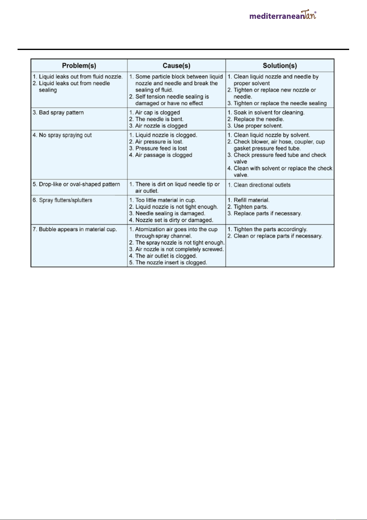
7. Hush Optimiser™Spray Gun Problems
14

HUSH endura
™
SPRINTER
RECORD OF Hush Sprinter™ USE
MODEL SERIAL# DATE PURCHASED
DATE HOURS OF USE TOTAL HOURS
15

HUSH endura
™
SPRINTER
RECORD OF Hush Sprinter™ MAINTENANCE
DATE MAINTENANCE PERFORMED
16

Solaire Warranty Card
Solaire Pty ltd
Name: Salon or Business Name:
Address:
Telephone Number: Mobile:
Email address:
Date of Purchase: Purchased from:
Proof of Receipt with matching serial number is copied and attached? Ye s No
Model: Serial Number:
I have read and understood the terms and conditions in the Solaire Warranty Card and I have completed the necessary requirements.
Purchaser’s Acknowledgement Signature: Date: / /
A warranty is provided with this piece of equipment provided it is used in conjunction with manufactures instructions and THE WARRANTY CARD IS RETURNED within 14 days
of receipt of purchase AND prior to use the purchaser acknowledges reading and fully understanding the Manufactures Instruction Manual. You must complete your spray tan gun
maintenance and equipment care training module. If you fail to complete all three of the above YOU VOID your warranty.
e most common cause of failure of any spray tan equipment is lack of cleaning, so take the time to make sure you look aer your investment. Please ensure you read the instructions
carefully and complete the spray tan gun maintenance and equipment care training module at www.solaire.com.au. You will need to register on the site prior to completing your
training. e website is also full of a whole range of products and education to help you as the spray tan specialist ensure you deliver the most professional customer service and an
award winning Solaire spray tan.
•Complete your contact details. Attach a copy of the original receipt showing the serial number. Email to: sales@solaire.com.au.
•Read the Manufactures Instruction Manual.
•Register at www.solaire.com.au and complete the spray tan gun maintenance and equipment care training module. is is found in the education tab on the le hand side of
the home page. Click on sunless education and watch the video.
MEDITERRANEAN TAN WARRANTY CARD
MEDITERRANEAN TAN PTY LTD
I have read and understood the terms and conditions in the Mediterranean Tan Warranty Card and I have completed the necessary requirements.
Mediterranean Tan spray tan.
Register at www.mtwb.com.au
www.mtwb.com.au

Solaire will extend a warranty on equipment as provided by the Manufactures Instruction Manual of the goods.
Solaire Pty Ltd warrants that products assembled by Solaire Pty Ltd shall be free from defects as it relates to Solaire Pty Ltd workmanship for a period as
outlined in the Manufactures Instruction Manual for each respective piece of equipment from the date of purchase from Solaire Pty Ltd or its distributors
or agents to the buyer.
If during the warranty period, the goods should prove defective as determined by Solaire Pty Ltd or its authorized repairer, then the Solaire can, at their
discretion, repair or replace the goods.
In no event shall Solaire Pty Ltd, manufacturer of goods, their subsidiaries and aliated companies, be liable for special, incidental, or consequential
damages, including loss of prots, whether or not caused by or resulting from negligence of seller. In addition, this warranty shall not apply to any goods
or portions thereof which have been subjected to abuse, misuse and improper installation, maintenance or operation, electrical failure or abnormal
conditions, and to goods which have been tampered with, altered, modied, repaired or reworked by anyone not approved by Solaire Pty Ltd.
Solaire Pty Ltd warranty herein is in lieu of and excludes all other warranties of seller and the distributor of the goods and their subsidiaries and aliated
companies, whether expressly implied, statutory or otherwise created under applicable law including, but not limited to, the warranty of merchantability
and the warranty of tness for particular purpose or use.
is Warranty does NOT include: misuse, damage, neglect, alterations, disassembled equipment or modications, lack of maintenance, cleaning, water
damage to electrical parts and INCORRECT VOLTAGE CONNECTION.
Warranty Procedure:
1. Email: sales@solaire.com.au to request a WARRANTY Claim Form. Fill in the WARRANTY claim form and email it to:
sales@solaire.com.au. Try to include as much detail as possible about the problem.
2. If at all possible we try to help you solve the problem and therefore you may be contacted regarding your claim either via phone or email. If we
are unable to solve the issue the equipment will need to be assessed and it will need to go to one of our Authorised repairers - we will issue you a
claim number.
3. Once you have your claim number insert the number on Warranty Claim Form.
4. Ensure equipment is clean, dry and securely wrapped to prevent any leaking of uid and well-padded and packaged to prevent damage to the
equipment during shipping.
5. Send the form with the goods to the address on the WARRANTY CLAIM FORM.
6. Send a copy of the receipt from the original purchaser showing serial number, place of purchase, date of purchase.
7. You will be required to pre - pay all shipping charges.
8. Our Authorized repairer will attend to you claim promptly and contact you to discuss aer they have assessed the claim.
Mediterranean Tan will extend the warranty on equipment as provided by the Manufacturers Instruction Manual of the goods.
Mediterranean Tan Pty Ltd warrants that products assembled by Mediterranean Tan Pty Ltd shall be free from defects as it relates to Mediterranean Tan
Pty Ltd workmanship for a period as outlined in the Manufacturers Instruction Manual for each respective piece of equipment from the date of purchase
from Mediterranean Tan Pty Ltd or its distributors or agents to the buyer.
If during the warranty period, the goods should prove defective as determined by Mediterranean Tan Pty Ltd or its authorised repairer, the Mediterranean
Tan can, at their discretion, repair or replace the goods.
In no event shall Mediterranean Tan Pty Ltd, manufacturer of goods, their subsidiaries and afliate companies, be liable for special, incidental, or
consequential damages, including loss of prots, whether caused by or resulting from negligence of seller. In addition, the warranty shall not apply to any
goods or portions there of which have been subjected to abuse, misuse and improper installation, maintenance or operation, electrical failure or abnormal
conditions, and to goods which have been tampered with, altered, modied, repaired or reworked by anyone not approved by Mediterranean Tan Pty Ltd.
Mediterranean Tan Pty Ltd warranty herein is in lieu of and excludes all other warranties of seller and distributor of the goods and their subsidiaries
and afliated companies, whether expressly implied, statutory or other wise created under applicable law including, but not limited to, the warranty of
merchantability and the warranty of tness for particular purpose or use.
This warranty does NOT include: misuse, damage, neglect, alterations, disassembled equipment or modications, lack of maintenance, cleaning, water
damage to electrical parts and INCORRECT VOLTAGE CONNECTION.
Warranty Procedure:
1. Email [email protected] to request a WARRANTY Claim Form. Fill in the WARRANTY claim form and email it to [email protected]. Try to
include as much detail as possible about the problem.
2. If at all possible we try to help you solve the problem and therefore you may be contacted regarding your claim either by phone or email. If we are
unable to solve the issue the equipment will need to be assessed and it will need to go to one of our Authorised repairers - we will issue you a claim
number.
3. Once you have your claim number insert the number on the Warranty Claim Form.
4. Ensure equipment is clean, dry and securely wrapped to prevent any leaking of uid and well-padded and packaged to prevent damage to the
equipment during shipping.
5. Send the form with the goods to the address on the WARRANTY CLAIM FORM.
6. Send a copy of the receipt from the original purchase showing the serial number, place of purchase, date of purchase.
7. You will be required to pre - pay all shipping charges.
8. Our Authorised repairer will attend to your claim promptly and contact you to discuss after they have assessed the claim.
Table of contents
Other MediterraneanTan Paint Sprayer manuals


