Medivators ADVANTAGE 78400-117 Technical specifications

ADVANTAGE®Annual Preventive
Maintenance Instructions
50097-056 Rev. A Page 1 of 12
These instructions should be followed to perform preventive maintenance on the Advantage reprocessor.
Before commencing work on the reprocessor, ensure that you have the appropriate parts and tools.
Parts Required
1. 78400-117 Advantage Annual PM Kit
Tools Required
1. Philips screwdriver
2. Straight blade screwdriver
3. 2.5mm Allen wrench
4. Needle nose pliers
5. Tubing cutter
6. Pliers
7. Wire clippers
8. Adjustable wrench
9. Silicone oil
10. Hand pump
Procedure
•Place the “Machine Disinfection” blocks in each basin.
•Remove the alcohol and detergent containers. Purge the alcohol and detergent lines by activating the
valves/pumps Y10, Y11, P0Z, and P0C in expert mode. When the lines are purged press the “release
all” button in the expert screen. Perform on both basins.
•Shutdown the computer, unplug the power to the unit and turn off the water.
•Remove the access panels on the left and right sides.
Note: While performing the PM check for internal and external fluid leaks.
ADVANTAGE®Annual Preventive
Maintenance Instructions
50097-056 Rev. A Page 2 of 12
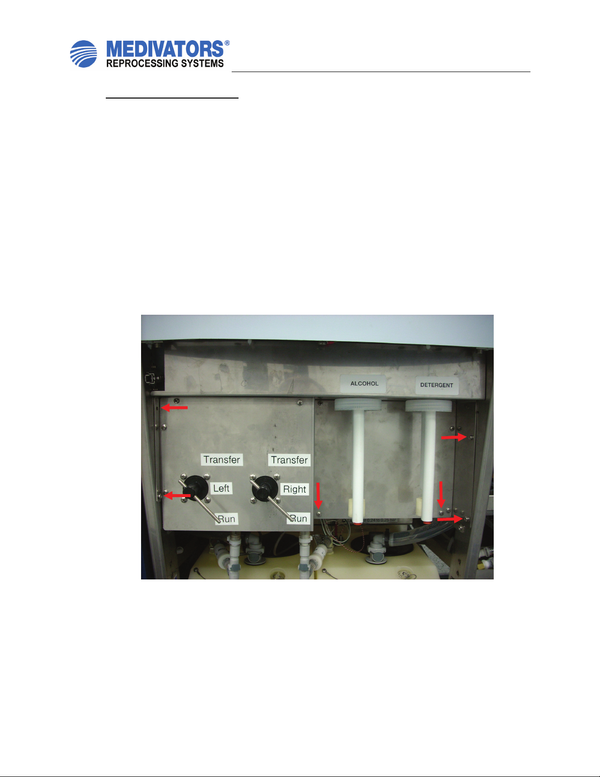
Disinfectant Pump Assembly
1. Remove the alcohol and detergent containers.
2. Remove the panel containing the transfer valves and the alcohol/detergent uptake tubes
by removing the six indicated screws. Disconnect the 2 electrical connectors and 6 tubing
connections. See figure 1.
3. Disconnect the 4 male, gray John Guest fittings from the white John Guest elbow fittings
attached to the disinfectant pump heads. While removing note the locations of the
connections. See figure 2.
4. Disconnect the two electrical connections.
5. Remove the two screws at the base of the assembly mounting plate. See figure 2.
6. Remove the entire disinfectant pump assembly and discard.
7. Place the new disinfectant pump assembly in place and attach with the two base screws.
8. Reattach the tubing fitting to the correct locations.
9. Reconnect the two electrical connections.
10. Replace the front panel and ensure all of the plumbing and electrical connections are
made on the backside of the panel.

ADVANTAGE®Annual Preventive
Maintenance Instructions
50097-056 Rev. A Page 3 of 12
Figure 1: Disinfectant Pump Assembly
Figure 2: Disinfectant Pump Assembly
ADVANTAGE®Annual Preventive
Maintenance Instructions
50097-056 Rev. A Page 4 of 12
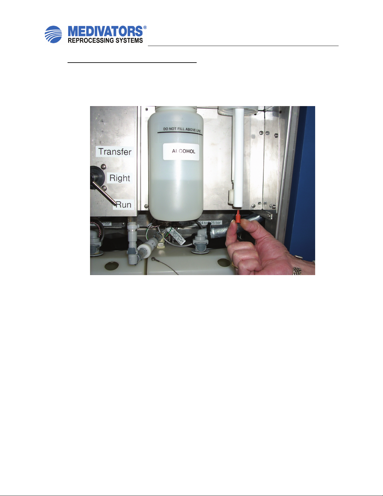
Alcohol and Detergent Uptake Check Valves
1. Remove the alcohol and detergent containers.
2. Remove the old check valves out of the bottom of the uptake tubes, discard. See figure 3.
3. Replace with new check valves, press into place.
4. Replace the alcohol and detergent containers.
Figure 3: Alcohol/Detergent Uptake Check Valve

ADVANTAGE®Annual Preventive
Maintenance Instructions
50097-056 Rev. A Page 5 of 12
Elevator Pump Diaphragm
1. Performed on both sides.
2. The elevator pump is located on the back side of the channel manifold.
3. Remove the 4 Allen screws with a 2.5mm Allen wrench. See figure 4.
4. Remove the circular assembly from the manifold. See figure 4.
5. Remove and discard the old diaphragm.
6. Place the new diaphragm in the channel manifold. When properly placed a small hole
should be visible in the center of the diaphragm. See figure 5.
7. Place the circular assembly back in its original position and reattach with the four Allen
screws.
Figure 4 and 5: Elevator Pump Diaphragm
ADVANTAGE®Annual Preventive
Maintenance Instructions
50097-056 Rev. A Page 6 of 12
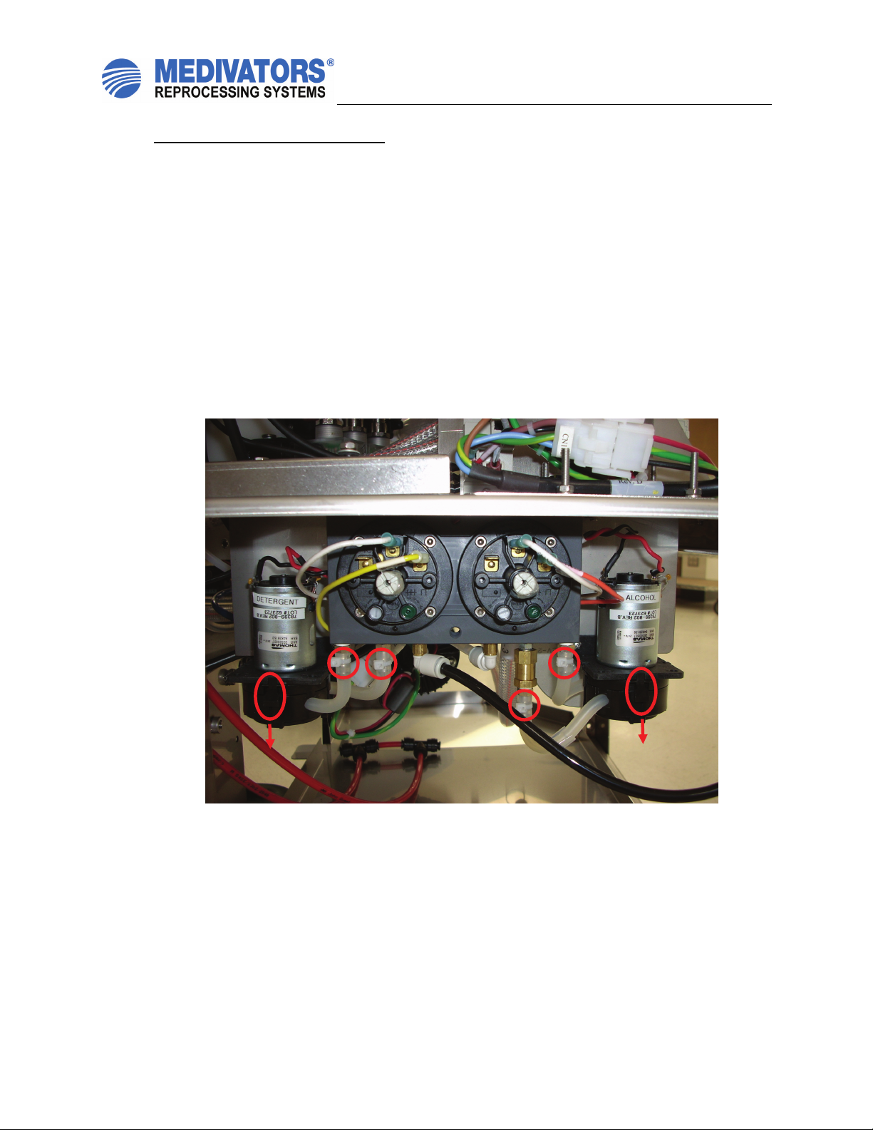
Alcohol and Detergent Pump Head
1. Performed on both sides.
2. Use wire cutters to remove the tie wraps from the tubing connections on the manifold. See
figure 6.
3. Remove the tubing from the barb fittings. Make note of the tubing positions. See figure 6.
4. Remove the old pump head by pressing in on the two black plastic tabs and firmly pull
down. Discard the old pump heads. See figure 6.
5. Place the new pump head on the motor assembly and press up firmly making sure it snaps
firmly in place. Note the orientation of the tubing.
6. The new tubing on the pump head will need to be cut to match the tubing length removed
to ensure no kinking of the tubing.
7. Connect the new tubing to the barbed fittings on the manifold again noting the original
locations.
8. Use the supplied wire ties to secure the tubing on the barbed fittings.
Figure 6: Alcohol and Detergent Pump Head

ADVANTAGE®Annual Preventive
Maintenance Instructions
50097-056 Rev. A Page 7 of 12
Channel Pump
1. Performed on both sides.
2. Check the tightness of the two band clamps on the channel pump. See figure 7.
3. If loose or signs of fluid leaks tighten the band clamps.
Figure 7: Channel Pump

ADVANTAGE®Annual Preventive
Maintenance Instructions
50097-056 Rev. A Page 8 of 12
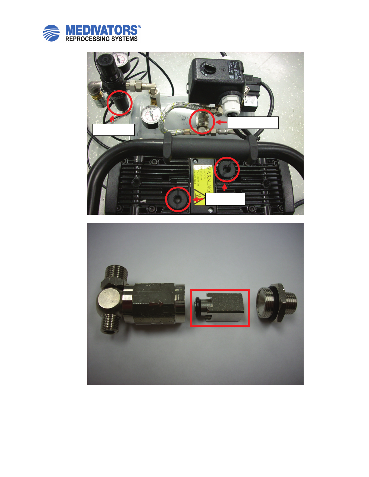
Air Compressor
Note: Skip this step if the Advantage unit being serviced does not use the air compressor.
Unplug the power from the compressor. Vent the air tank by pulling the pressure relief ring located
underneath the pressure switch.
Air Intake Filters
1. Remove the two air filters located on the top of the compressor by unscrewing
counter clockwise. Discard the old filters and install the two new filters. See
figure 8.
5µm Filter
2. Unscrew the lower housing of the 5µm filter. See figure 8.
3. Remove the old filter by unscrewing it and replace with the new filter.
4. Replace the housing o-ring with the supplied o-ring and lubricate with silicone oil.
5. Replace the lower housing, hand tighten only.
Check Valve
1. Locate the check valve assembly underneath the pressure switch.
2. Remove the two braided stainless steel hoses from the end of the check valve by
loosening the two fittings. See figure 8.
3. Unscrew the check valve housing, the base of the housing will stay on the air tank.
4. Carefully remove the housing noting the order of the internal parts.
5. Clean and inspect the inside of the housing.
6. Disassemble the new check valve and replace the internal parts of the old check
valve with the internal parts of the new check valve. Ensure all pieces go back in
the proper order. See figure 9.
7. Reattach the check valve housing to the air tank.
8. Reattach the two braided stainless steel tubing.
Note: When the compressor is repowered check for leaks.
Note: The kit includes a 0.1µm filter kit which is only used on the older style compressor. The
filter replacement procedure is the same as the 5µm filter noted above.
ADVANTAGE®Annual Preventive
Maintenance Instructions
50097-056 Rev. A Page 9 of 12
Figure 8: Air Compressor
Figure 9: Air Compressor Check Valve
5
µ
m Filte
r
A
ir Filters
Check Valve

ADVANTAGE®Annual Preventive
Maintenance Instructions
50097-056 Rev. A Page 10 of 12
Air Filters
1. Performed on both sides.
2. Each side has two air filters located towards the front of the unit.
3. Replace the filters one at time in order not to cross the tubing connections.
Basin Connector O-rings
1. Performed on both sides.
2. Replace the 8 o-rings on the basin connector posts.
3. Lightly lubricate each o-ring with silicone oil.
Basin Drain Filter
1. Performed on both sides.
2. Replace the basin drain filter located in basin drain.
Plug the Advantage power back in, turn on the water and restart the computer.
Pressure Switch Settings
There are a total of 10 pressure switches per basin (8 on the channel manifold, and 2 on the
alcohol & detergent dosing unit. There are two switch levels that must be checked for each
pressure switch:
•Upper level (Moment of switching on as pressure is increased)
•Lower level (Moment of switching off as pressure is decreased)
Sensor Adjust Value Tolerance Remarks
Leaktest 60 - 50 mmH
g
± 2 mmH
g
Jet 120 - 100 mmH
g
± 2 mmH
g
Biops
y
50 - 40 mmH
g
± 2 mmH
g
Air 120 - 100 mmHg ± 2 mmHg
Suction 50 - 40 mmHg ± 2 mmHg
Water 120 - 100 mmH
g
± 2 mmH
g
Extra 50 - 40 mmH
g
± 2 mmH
g
Elevator 280 - 220 mmHg ± 10 mmHg Activate Y10
Alcohol 80 - 70 mmHg ± 2 mmHg Activate Y10 & Y1 1
Detergent 50 - 40 mmHg ± 2 mmHg
ADVANTAGE®Annual Preventive
Maintenance Instructions
50097-056 Rev. A Page 11 of 12
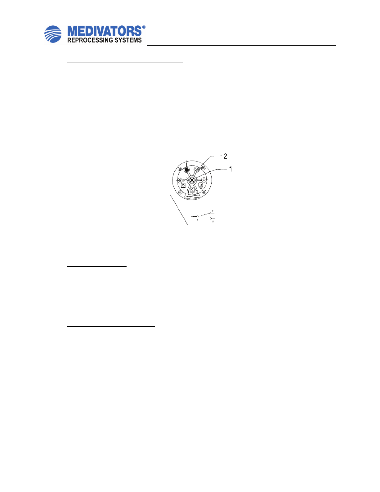
Adjusting Pressure Switches (If necessary)
1. The pressure switches should be set correctly, however, it is necessary to verify the
correct settings, and make any adjustments if needed.
2. Connect the hand pump to the appropriate channel.
3. Increase pressure using hand pump until the switch activates.
4. Verify pressure level for activation.
5. Slowly decrease pressure on hand pump until the switch deactivates.
6. Verify pressure level for deactivation.
7. If any adjustments are necessary to the pressure switches, adjust the central screw 1 to
set the upper level. Adjust screw 2 to set the difference in upper and lower levels.
Pressure Regulators
Adjust pressure regulators as follows:
General: 3.0 bar (± 0.1 bar)
Leak Test: 0.25 bar
Connectivity: 1.9 bar
Channel pump: 24 psi (± 1 psi)
Setting channel pump regulators
1. Ensure WLD block in installed in basin
2. Using the expert screen, fill basin with several inches of water by closing the drain, and
turning on water supply.
3. Turn on the channel pump, open the spray head, and open each of the channels one by
one to prime the lines.
4. After lines are primed, close the spray head and all the channels. Remember that the
elevator channel is normally open, and must be activated to close.
5. At this point, the channel pump should be pumping against a deadhead (no flow).
6. Adjust the channel pump regulator for 24 psi (± 1 psi) with the pump deadheaded.
7. Secure the regulator’s adjusting knob by pressing it in.
•Update the software if necessary

ADVANTAGE®Annual Preventive
Maintenance Instructions
50097-056 Rev. A Page 12 of 12
•Reattach the alcohol and detergent containers. Prime the alcohol and detergent lines in expert mode
for both sides.
1. For detergent activate P0Z until detergent starts entering the basin, then press “release
all”.
2. For alcohol activate Y10, Y11, and P0C until alcohol starts entering basin through the
elevator port on the hookup block, then press “release all”.
•Run test cycles on both sides and check for fluid leaks
•No waterline disinfection is needed unless work on the water supply valves or the pre-filters has been
performed
•Perform a backup, follow procedure 50096-867
Table of contents
Other Medivators Laboratory Equipment manuals


