Medivators CER User manual

WATER FILTRATION SYSTEM
INSTALLATION INSTRUCTIONS
CER/CLM
Endoscope reprocessing the way it should be™
NOTE: When replacing lter housing hand tighten only. The lter wrench should only be
used to remove a lter housing.
PURPOSE
These instructions cover the installation of the water ltration system (PN CER-1076) used with the
MEDIVATORS brand CER and CLM endoscope reprocessors.
WATER SUPPLY
Use a cold water line with a pressure of 40 to 60 PSI that will supply a ow rate of 2.5 to 3 GPM (9.4 LPM to
11.4 LPM) lter system. The cold water supply should not exceed 110°F (43°C).
FILTRATION SYSTEM
NOTE: Endoscope manufacturers recommended that endoscopes not be exposed to
temperatures above 130°F (55°C).
NOTE: A water shut-off valve is required before the lter assembly. It should be
accessible to the users.
NOTE: THE WATER SUPPLY IS REQUIRED TO BE TURNED OFF WHEN NOT IN USE.
1
2
3
Gauge #1
Gauge #2
Gauge #3
To incoming water supply
Female Quick-connect
Male Quick-connect
3/4-inch hose connection
Filter housing
Pre-lter
Filter wrench
To CER water supply
connection
3/4-inch hose
connection
Filter housing
Final Filter
Stainless steel hose
Figure 1. Filtration System

The ltration system consists of the following components:
• Filtration System main assembly (Figure 1)
• Pre Filter: 1 micron lter (reorder #: MF01-0014)
• Final Filter: 0.2-micron bacterial lter (reorder # CF01-0018)
• Filter Wrench (CW03-0000)
• Stainless Steel Hose (CH06-0000)
• Male quick-connect tting (MC10-0042)
• Female Quick-Connect (MC10-0043)
NOTE: Do not remove the Male/Female quick connectors in Figure 1. These are required
to disinfect the lters and water line.
INSTALLATION
4
15 inches
16 inches
Depth of unit is approximately 6-inches.
Figure 2. Water Filtration System Dimensions
2

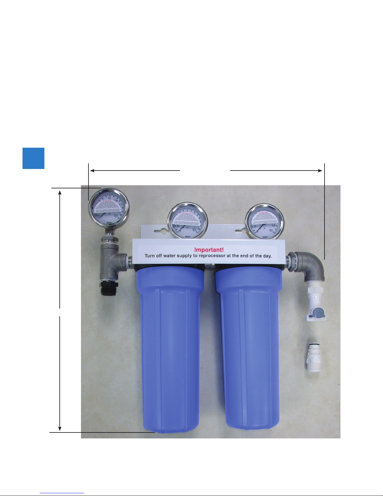
Approximate dimensions of the water lter are shown in gure 2.
• For wall mounting: Mount the lter assembly on the wall where the pressure gauges can be read easily.
Allow a minimum of 30 inches under the assembly for removal of the lter housings and 2.5 inches on
each side for connection of hoses.
• For cart mounting: Mount the lter assembly in the supplied cart. The pressure gauges should be
visible when the right hand access panel is removed.
• Tap into the facility cold water supply line and install a 3/4 inch male hose tting (not included). This
will require a qualied plumbing installer.
• Using a customer supplied hose which is connected to the cold water supply, connect the other end
of the hose to the male quick connect and attach the male quick connect to the female quick connect
on the water lter assembly. This quick connected arrangement allows the use of the transfer pump for
performing the water line disinfection.
• Attach the 3/4 inch hose connection to one end of the supplied stainless steel hose and the other end
to the water inlet of the reprocessor.
NOTE: Any time the nal lter (0.2 micron) is changed, the water line must be
disinfected (Section 6)
CAUTION: When changing lters, hand tighten the lter housing. Only use the lter
wrench to remove housing.
NOTE: The pre-lter should be changed every three months, even if water pressure is good.
The nal lter should be changed at a minimum every six months, even if the water
pressure is good.
FILTER REPLACEMENT
The accumulation of particles in a lter can cause the water pressure to drop below the minimum required
level (40 PSI). This depends on water quality which cannot be guaranteed by MEDIVATORS. The pressure
drop across the lters is used to determine when the lter(s) should be changed. For example: A pressure
differential of 5 PSI or greater between gauges on each side of a lter indicates a need for replacement. For
example, if the pressure on gauge #1 is 35 PSI when the pressure on gauge #2 is 40 PSI, a lter change is
required.
• Turn off the water supply to the ltration system.
• Press START on the reprocessor to remove the pressure from the lter housings.
• Press STOP.
• Remove lters, clean the housings with a mild general-purpose detergent and water, then rinse
thoroughly.
• Place the new 1-micron lter cartridge into the pre-lter housing. Both ends of this lter are open.
Ensure that the large O-ring is seated and centered in the end of the lter when it is inserted into the
housing. Thread the housing onto its header and hand tighten.
• Place the new 0.2-micron bacterial-retentive lter cartridge into the nal-lter housing. Only one end
of this lter is open and has an O-rings. Ensure that the O-ring ts tightly on the peg in the top of the
housing. Thread the housing onto its header and hand tighten.
5
3

NOTE: To ensure seal integrity, the use of a water-based lubricant on the post-lter O-ring
is recommended.
DISINFECTION OF FILTRATION SYSTEM
Using Liquid Chemical Germicide Transfer Pump (reorder # DSD-1087).
Figure 3. Transfer Pump and Disinfectant connected to Filtration System.
• Turn off the water supply to the ltration system.
• Disconnect the water line from the inlet side of the ltration system.
• Connect the outlet of the transfer pump to the inlet side of the ltration system.
• Insert the inlet tubing of the transfer pump into a one-gallon container of high-level disinfectant.
• Press START on the reprocessor.
• Turn on the transfer pump until the disinfectant solution starts owing continuously in the basin.
• Press STOP on the reprocessor.
• Turn off the transfer pump.
• Allow the reprocessor and the lters to soak for the time recommended on the product label of the high-
level disinfectant for high-level disinfection.
• Reconnect the water line to the inlet side of the ltration system.
• Turn on the water supply to the ltration system.
• Press START and allow the wash cycle to run in order to rinse the disinfectant out of the system. When
all of the water has drained, press STOP.
6
Filtration system
Transfer Pump
Disinfectant
4

Without using the transfer pump
• Turn off the water supply to the ltration system.
• Remove and ll each housing with approximately 38 ounces (1.12 liters) of high-level disinfectant and
replace on header (see Filtration Replacement)
• Allow the lters to soak for the time recommended on the product label of the high-level disinfectant for
high-level disinfection.
• Turn on water supply to the ltration system
• Press START and allow the wash cycle to run in order to rinse the disinfectant out of the system. When
all of the water has drained, press STOP.
5

© 2015 Medivators Inc. MI02-0107/L
MEDIVATORS Website “Resource Center”
Go to: www.medivators.com, Select “Resource Center” and “User Library” for detailed user guides and hook-up
information, report forms and logs, and product bulletins
MEDIVATORS Technical Support Toll Free: Phone: 1-800-444-4729 ·FAX: 1-866-421-7696
www.medivators.com
Manufactur
ed in the USA by:
Medivators Inc.
14605 28th A
venue North
Minneapolis, MN 55447 USA
T
oll Free: +1.800.444.4729
Medivators BV
Sourethweg 11
6422PC Heerlen
The Netherlands
Tel: +31.45.5.471.471
Cantel Medical Asia/Pacic Pte Ltd
1A International Business Park
#05-01 Singapore 609933
Tel: +65.6227.9698
Cantel Medical Devices (China) Co. Ltd.
Unit 804-805, Innov Tower Block A,
Hongmei Road, Xuhui 200233 Shanghai
Tel: +86 21 60161380
Fax: +86 21 61210913
6
This manual suits for next models
1
Table of contents
Other Medivators Water Filtration System manuals
Popular Water Filtration System manuals by other brands

EM-Technik
EM-Technik 7F800 Operation and assembly instructions

Culligan
Culligan 9" Installation, operation and service instructions

Ecosoft
Ecosoft MO-12 instruction manual

LG
LG Premium 5231JA2002A-S installation and replacement

PET
PET Ecoflo ST-500 owner's manual

PREMIER TECH
PREMIER TECH Rewatec Ecoflo EC-2.8 Quick reference guide