Hydrotech Water NOVO 665AIO User manual

Installation and Operation Manual
665AIO
Chem Free
Hydrogen Sulphide
Reduction FIlter
REVISION # 0
REVISION DATE May 4,2015
54855
FOLLOW THE INSTALLATION INSTRUCTIONS CAREFULLY. FAILURE TO
INSTALL THE UNIT PROPERLY VOIDS THE WARRANTY. BEFORE YOU
BEGIN INSTALLATION, READ THIS ENTIRE MANUAL. THEN, OBTAIN ALL
THE MATERIALS AND TOOLS
1. Avoid pinched o-rings during installaon by applying (provided with install kit) NSF cered lubri-
cant to all seals.
2. This system is not intended for treang water that is microbiologically unsafe or of unknown
quality without adequate disinfecon before or aer the system.
3. Filters are commonly exposed to high levels of iron, manganese, sulfur, and sediments. Damage
to pistons, seals, and or spacers within the control valve are not covered in this warranty due to
the harsh environment.
4. It is recommended to regularly inspect and service the control valve on an annual basis. Cleaning
and or replacement of piston, seals, and or spacers may be necessary depending how harsh the
condion are.

2
Safety Guide
For your safety, the information in this manual must be followed to minimize the risk of
electric shock, property damage or personal injury.
Be sure to check the entire unit for any shipping damage or parts loss. Also note damage to
the shipping cartons. Contact the transportation company for all damage and loss claims.
The manufacturer is not responsible for damages in transit.
Small parts, needed to install the softener, are in a parts bag. To avoid loss of the small
parts, keep them in the parts bag until you are ready to use them.
Unpacking / Inspection
PAGE
Unpacking / Inspection 2
Safety Guide 2
Proper Installation 3
Specification 4
Before Starting Installation 6
Sizing Requirements 8
Installation Instructions 9
System Start Up 11
Plumbing System Clean-Up 12
Programming Instructions 13
About The System 14
Maintenance 16
Main Repair Parts 20
Trouble Shooting 25
Warranty 26
Table of Contents
Check and comply with your provincial /
state and local codes. You must follow
these guidelines.
Use care when handling the filter tank. Do
not turn upside down, drop, drag or set on
sharp protrusions.
The system works on 12 volt-60 Hz electri-
cal power only. Be sure to use only the
included transformer.
Transformer must be plugged into an in-
door 120 volt, grounded outlet only.
WARNING: This system is not intend-
ed for treating water that is microbiologi-
cally unsafe or of unknown quality without
adequate disinfection before or after the
system.

3
Proper Installation
This water filter system must be properly installed and located in accordance with the
Installation Instructions before it is used.
Install or store where it will not be ex-
posed to temperatures below freezing or
exposed to any type of weather. Water
freezing in the system will break it. Do not
attempt to treat water over 100°F.
Do not
install in direct sunlight. Excessive
sun or heat may cause distortion or other
damage to non-metallic parts.
Properly ground to conform with all gov-
erning codes and ordinances.
Use only
lead-free solder and flux
for all
sweat-solder connections, as required by
state and federal codes.
The water filter system requires a mini-
mum water flow of three gallons per mi-
nute at the inlet.
Maximum allowable inlet water pressure is
125 psi. If daytime pressure is over 80
psi, night time pressure may exceed the
maximum. Use a pressure reducing valve
to reduce the flow if necessary.
WARNING:
Discard all unused parts and
packaging material after installation. Small
parts remaining after the installation could
be a choke hazard.

4
Specifications
Continuous operation at flow rates greater than the service flow rate may affect capacity and efficiency performance.
The manufacturer reserves the right to make product improvements which may deviate from the specifications and
descriptions stated herein, without obligation to change previously manufactured products or to note the change.
Min / Max Water Temperature = 39°F / 100°F
Min / Max Operating Pressure = 30 PSIG / 125 PSIG
Voltage = 110 volts 50/60Hz standard
Peak flow rates are intended for intermittent use only
and are for residential application only
At the stated service flow rates, the pressure drop
through these devices will not exceed 15 psig
Item # Model Media Cu Ft
Flow Rate USGPM Mineral
Tank Size
Pipe Size
Inches
Ship
Weight
Lbs
Service Peak Back-
AIO (Air Inducon Oxidizer) Chemical Free Iron Filter (Single
FILTER, NVO665FAIO75
0.75 243.5 8 x 44 3/4" 110
FILTER, NVO665FAIO10
1.0 3649 x 48 3/4" 145
FILTER, NVO665FAIO15
1.5 410 510 x 54 3/4" 250
FILTER, NVO665FAIO75M
0.75 243.5 8 x 44 3/4" 110
FILTER, NVO665FAIO10M
1.0 3649 x 48 3/4" 145
FILTER, NVO665FAIO15M
1.5 410 510 x 54 3/4" 250
Item # Model Cat Carbon
Cu Ft
Flow Rate USGPM Mineral
Tank Size
Pipe Size
Inches
Ship
Weight
Lbs
Service Peak Back-
FILTER, NVO665FAIOC75
0.75 243.5 8 x 44 3/4" 110
FILTER, NVO665FAIOC10
1.0 3649 x 48 3/4" 145
FILTER, NVO665FAIOC15
1.5 410 510 x 54 3/4" 250
15010670
15010671
15010672
15010674
15010675
15010676
15010677
15010678
15010679

5
How does the Chemical Free AIO Iron Filter
work?
This filter works by adding oxygen to the incoming wa-
ter by passing it through a bubble of compressed air.
The water is then passed through a special filter bed.
The special media not only increases the pH of the
water to enhance iron removal but also acts as a
physical barrier to trap iron precipitate.
As more water passes through this iron filter, the oxy-
gen in the unit is used up, and the media gets loaded
with iron. The regeneration process then begins in
order to replenish the supply of oxygen, and to back-
wash the precipitated iron trapped in the media bed.
The iron removal efficiency will be more effective with
high pH water.
Optional Media Beds:
• Birm - Removes iron and manganese from water.
Recommended for high pH water.
• nextSand or Multimedia- Traps precipitated iron
from the water. Recommended for high pH water.
AIO Standard Chemfree Filter
This special media not only increases the pH of the
water to enhance iron, manganese and hydrogen sul-
fide removal but also acts as a physical barrier to trap
iron precipitate.
The filter will automatically adjust the pH to neutral or
higher on acid water without an acid neutralizer. The
ability to raise pH greatly enhances the filter’s ability to
remove iron efficiently.
Replenishment of this media that raises pH will be re-
quired periodically, depending on how low the raw wa-
ter pH is the amount of manganese (Mn) present in
the water and usage rate.
AIO Birm Filter
This media acts as a catalyst for the removal of iron
and manganese from the water but require pre-
oxidation. The water is pre-oxidized from the air bub-
ble on the top of the tank and this media removes the
iron and manganese from the water. This is not rec-
ommended to remove hydrogen sulfide from the water
and requires high pH water.
The media is not sacrificial hence no replenishment is
required
IRON (Fe)
Iron concentrations as low as 0.3 ppm will
cause staining. The iron concentration, to-
gether with the flow rate demand and the
consumption rate of the water determines
the basic size filter system. The higher these
factors are, the larger the required system.
The filter system is capable of filtering out
the three main types of iron found in water
supplies: Soluble iron (also known as “clear
water” or ferrous iron), precipitated iron (also
known as “red water” or ferric iron) and bac-
terial iron (also known as iron bacteria).
There is no apparent upper limit of iron con-
centration for the filter, but special care must
be taken when selecting a filter model if your
water has a combination of high iron, very
low pH and/or manganese.
MANGANESE (Mn)
The presence of manganese can be bother-
some, even for a chemical free iron filter. As
little as 0.05 ppm of manganese can produce
a brownish or black stain. The ability of the
filter to remove manganese depends on its
concentration and the pH of the water.
Manganese tends to “coat” the filter media,
rendering it incapable of increasing the pH,
and therefore ineffective in removing either
the iron or the manganese. Manganese, how-
ever, will precipitate in the filter bed when
the pH is increased. To accomplish this a spe-
cial “MN” type media can be provided that
contains additional quantities of the pH rais-
ing component (“MN adder”). The use of
“MN” type media is for applications where
the manganese is not more than 1.5 ppm,
and the pH is at least 6.5.
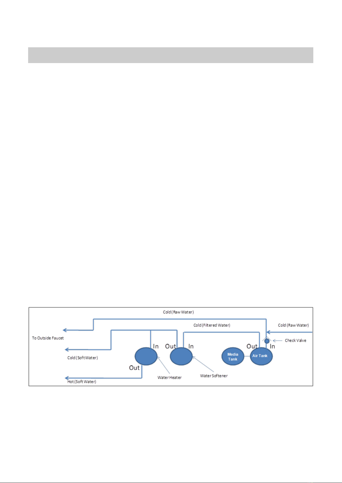
How The System Works

6
Before Starting Installation
Tools, Pipe, and Fittings, Other Materials
Pliers
Screwdriver
Teflon tape
Razor knife
Two adjustable wrenches
Additional tools may be required if modifi-
cation to home plumbing is required.
Plastic inlet and outlet fittings are included
with the filter. To maintain full valve flow,
3/4” or 1” pipes to and from the filter fit-
tings are recommended. You should main-
tain the same, or larger, pipe size as the
water supply pipe, up to the filter inlet and
outlet.
Use copper, brass, or PEX pipe and fittings.
Some codes may also allow PVC plastic
pipe.
ALWAYS install the included bypass valve,
or 3 shut-off valves. Bypass valves let you
turn off water to the filter for repairs if
needed, but still have water in the house
pipes.
5/8” OD drain line is needed for the valve
drain. A 10’ length of hose is included.
with some models.
pH
The pH of water measures its acidity or its
alkalinity. Water with a pH of less than 7.0 is
acidic, above 7.0 it is alkaline, and a pH of
7.0 is neutral. The lower the pH value is be-
low 7.0 the greater the acidity, and the high-
er the pH value is above 7.0 the more alka-
line. Acidic water (pH less than 7.0) is corro-
sive to pipes, appliances, etc. A pH of 7.0 or
higher facilitates iron removal —which is
why the filter is designed to increase the pH
when it is less than 7.0.
TANNINS (Humic Acid)
Tannins (also known as humic acid) which
are present in some water supplies, are the
result of decaying vegetable matter. If the
tannin concentration is above approximately
0.5 ppm, it will form a sticky coating on the
media, thus rendering it incapable of filtering
the iron. A chemical free iron filter is not rec-
ommended under this condition. If the tannin
concentration is less than 0.5 ppm, a chemi-
cal free iron filter may be installed.
HYDROGEN SULFIDE (H2S)
Hydrogen sulphide (often referred to as
“sulphur”), is easily detectable by its objec-
tionable “rotten egg” odour. Sulphur corrodes
iron, brass, copper and silver. A chemical free
iron filter is capable of removing sulphur in
concentrations of up to 3 to 5 ppm. Whenev-
er hydrogen sulphide is present, backwashing
must be performed at more frequent inter-
vals.

7
Place the filter tank as close as possible to
the pressure tank (well system) or water
meter (city water).
Place the filter tank as close as possible to
a floor drain, or other acceptable drain
point (laundry tub, sump, standpipe, etc.).
Connect the filter to the main water supply
pipe BEFORE the water heater. DO NOT
RUN HOT WATER THROUGH THE FIL-
TER. Temperature of water passing
through the filter must be less than 100
deg. F.
Keep outside faucets on hard water to
save soft water and salt.
Do not install the filter in a place where it
could freeze. Damage caused by freez-
ing is not covered by the warranty.
Put the filter in a place water damage is
least likely to occur if a leak develops. The
manufacturer will not repair or pay for wa-
ter damage.
A 120 volt electric outlet, to plug the in-
cluded transformer into, is needed within 6
feet of the filter. The transformer has an
attached 6 foot power cable. Be sure the
electric outlet and transformer are in
an inside location, to protect from
wet weather.
If installing in an outside location, you
must take the steps necessary to assure
the filter, installation plumbing, wiring,
etc., are as well protected from the ele-
ments, contamination, vandalism, etc., as
when installed indoors.
Keep the filter out of direct sunlight.
The sun’s heat may soften and distort
plastic parts.
Where To Install The Filter

8
Sizing Requirements
This unit is factory set for backwash every 4 days. More frequent backwash may be re-
quired based on water conditions and amount of water used.
Water Pressure
The water system must have a pump big enough to deliver the recommended backwash
rate with a minimum pressure at the inlet of the filter of 30 psi. If the existing system can-
not do this, it must be upgraded to do so. Whenever possible, the water system should be
adjusted to deliver at least 30 psi for even more satisfactory results.
Backwash Flow Rates
The most important criteria in sizing an iron filter is the capacity of the pump. The water
must pass through the filter media at a service flow rate that allows it to oxidize and collect
the iron. The filter must also be backwashed at a flow rate sufficient to dislodge and remove
the captured iron. Failure to provide sufficient water will cause a build-up of iron in the filter
media, impairing its iron removing ability and resulting in iron bleeding out into the service
water. In order for your filter to backwash and rinse properly, your pump must be capable of
providing the backwash flow rates indicated on page 4.
Check Your Pumping Rate
Two water system conditions must be checked carefully to avoid unsatisfactory operation or
equipment damage:
1. Minimum water pressure required at the filter tank inlet is 20 psi.
2. Measuring the pumping rate of your pump:
With the pressure tank full, draw water into a container of known volume, and measure the
number of gallons drawn until the pump starts again. This is draw-down. Divide this figure
by cycle time and multiply the result by 60 to arrive at the pumping rate in gallons per mi-
nute (gpm). To aid in your calculation, insert the date in the following formula:
DRAW-DOWN ______ ÷ CYCLE TIME _______ x 60 = PUMPING RATE ________ (gals)
(secs.) (Gpm)
EXAMPLE: CYCLE TIME is 53 seconds. DRAW-DOWN is 6 gallons; then, PUMPING
RATE equals:
6 gallons ÷ 53 seconds x 60 = 6.8 gpm
See chart on page 3 for minimum flow rates.
NOTE: If your pumping rate is inadequate for the model, do not install your filter until
the problem has been corrected.
Backwash Frequency

9
1. Locate the Media Tank close to a drain where the system will be installed. The surface
should be clean and level.
2. Shut off all water at main supply. On a private well system, turn off power to pump and
drain pressure tank. Make certain pressure is relieved from complete system by opening
nearest faucet to drain the system. Shut off fuel supply to water heater.
3. Cut the main supply line as required to fit plumbing to the control valve with bypass.
4. Solder or solvent weld plumbing. Do not apply heat to any fitting connected to the control
valve as damage may result to the internal parts. Check to be certain water supply pipe is
connected to the control valve inlet fitting and pipe connected to control valve outlet fit-
ting is in direction of house service.
5. Perform all plumbing according to local plumbing codes. Use a ½” minimum pipe or tub-
ing size for the drain line. Use a ¾” pipe or tubing for backwash flow rates that exceed 7
gpm or length that exceeds 20ft (6 m). NOTE: ON COPPER PLUMBING SYSTEMS BE
SURE TO INSTALL A GROUNDING WIRE BETWEEN THE INLET AND OUTLET
PIPING TO MAINTAIN GROUNDING.
6. Any solder joints near the valve must be done before connecting any piping to the valve.
Always leave at least 6" (152 mm) between the valve and joints when soldering pipes
that are connected to the valve. Failure to do this could cause damage to the valve.
7. Install ¾” check valve on inlet of bypass valve.
8. Connect the drain line to the valve.
9. Place unit in the bypass position.
10.Slowly turn on the main water supply.
11.At the nearest cold treated water tap nearby remove the faucet screen, open the faucet
and let water run a few minutes or until the system is free of any air or foreign material
resulting from the plumbing work. Close the water tap when water runs clean.
Installation Instructions

10
System Start-Up
Start-up Instructions
Key Pad Configuration
SETTINGS This funcon is to enter the basic set up informaon required at the
me of installaon.
MANUAL REGEN This buon has two funcons. The rst is to iniate an immediate or
delayed manual regeneraon. The second is while in programming
mode, pressing this key allows the user to change the value of each
seng.
DOWN / UP Increase or decrease the value of the sengs while in the program-
ming mode.
1. Plug the power transformer into an ap-
proved power source. Connect the power
cord to the valve.
2. When power is supplied to the control, the
screen will display “INITIALIZING WAIT
PLEASE” while it finds the service position.
3. Manually step the valve past the BRINE
position to the BACKWASH position. If
screen is locked, press SETTINGS for 3
seconds to unlock. Press and hold the
MANUL REGEN. Key for 3 seconds. Press
any key to skip the BRINE cycle.
4. (CARBON UNITS) Open the inlet on
the bypass valve slightly and very
slowly allow water to enter the unit.
(If the water enters too quickly it will
push the media or carbon up into the
control valve and get plugged).
5. Once the unit has filled sufficiently
that water is at least equal to the
height of the top of the media shut
down the water for 15 –20 minutes
for the carbon to soak. Unplug the
power cable. After the carbon has
soaked for the recommended time
continue by plugging the power cable
back in.
6. (CHEMFREE UNITS) Open the inlet on
the bypass valve slowly and allow water to
enter the unit. (The outlet of the bypass
should remain closed to prevent any fines
or debris from entering the plumbing sys-
tem) Allow all air to escape from the unit
before turning the water on fully then al-
low water to run to drain for 3-4 minutes.
7. Unplug the power cord from the power
supply, open inlet. Check the drain line
flow. Allow the water to run for 30
minutes.
8. Press any button to advance to the RINSE
position. Check the drain line flow. Allow
the water to run for 3-4 minutes or until
the water is clear.
9. The valve will automatically advance to
the SERVICE position. Open the outlet
valve on the bypass, then open the near-
est treated water faucet and allow the wa-
ter to run until clear, close the tap and re-
place the faucet screen.
10. Program unit.

11
Plumbing System Clean-Up
The following procedures are guidelines only
but have proven successful in most instanc-
es. Under no circumstances should any pro-
cedure outlined below be followed if contrary
to the appliance manufacturer's instructions.
Should there be any questions concerning
the advisability of performing a procedure, it
is strongly recommended the manufacturer's
authorized service outlet be consulted prior
to performing the procedure.
The plumbing system and water using appli-
ances that have been exposed, even for a
short time, to iron-fouled water need to be
cleaned of the precipitated iron that has col-
lected in them or iron bleed (staining) will
continue to be a problem.
Depending on the amount of iron in the wa-
ter and the length of time the water system
has been exposed to iron fouling, select from
the following procedures those that apply to
the type of system and appliances that need
to be cleaned to assure iron-free water at all
points of use.

12
If the water heater has been exposed to both
iron and hardness for a long period of time,
replacement of the heater tank may be the
only practical solution to prevent continued
staining originating from this source. After
completing the installation of the chemical
free iron filter, clean the water heater by fol-
lowing these instructions:
1. Shut off the energy supply to the water
heater and close the heater inlet water
valve.
2. Drain hot water tank completely. Open in-
let water valve, allowing heater tank to be
refilled with iron-free water. Continue
flushing until the water runs clear to the
drain.
3. If, after approximately 30 minutes of flush-
ing, water does not clear, terminate the
flushing operation. Refill hot water heater
with water and pour approximately 1/2
gallon of household bleach into the top of
the heater tank. Allow bleach solution to
stand in tank for 20 to 30 minutes. Flush
the tank again until water is clear at the
drain. Turn energy supply on.
NOTE: If water does not clear in approxi-
mately 10 minutes, water heater should
probably be replaced.
Water Heater
Programming Instructions
1. Press SETTINGS to enter programming. If the system has been inactive, you may
have to hold and press SETTINGS to unlock the display screen. Press UP or DOWN to
select which setting to modify.
2. To adjust a value, MANUAL REGEN. When the display flashes, the value may be
changed. Press UP or DOWN to change the value. Press MANUAL REGEN again to ac-
cept the value.
3. Press UP or DOWN to advance to the next option.
4. At any time, press SETTINGS to return to previous home screen menu.
Menu - Level 1
Press SETTINGS key
TIME
12:00AM
REG.TIME
12:00AM
DAYS
3
Example
Page 1 STAR
PLUMBing
Page 2 TEL (552)
764-1234

13
About The System
Manual Regeneration (Step / Cycle Valve)
If screen is locked, press and hold SETTINGS for 3 seconds to unlock. To initiate an imme-
diate regeneration, press and hold the MANUAL REGEN key for 5 seconds. The valve will
immediately start into manual regeneration.
To initiate a delayed regeneration, press the MANUAL REGEN key once to turn on and a re-
generation will be queued at the next pre-set regeneration time (i.e. 2:00 a.m.).. To cancel,
press the MANUAL REGEN key again.
Operation During A Power Failure
In the event of a power failure, the valve will keep track of the time and day for 48 hours.
The programmed settings are stored in a non-volatile memory and will not be lost during a
power failure. If power fails while the unit is in regeneration, the valve will finish regenera-
tion from the point it is at once power is restored. If the valve misses a scheduled regener-
ation due to a power failure, it will queue a regeneration at the next regeneration time once
power is restored.
Main Display
When power is supplied to the control, the screen will display TIME OF DAY, GALLONS RE-
MAINING, and DEALER NAME and PHONE NUMBER.
The brine tank is equipped with a safety float which prevents your brine tank from overfill-
ing as a result of a malfunction such as a power failure.
Safety Float
New Sounds
You may notice new sounds as your water softener operates. The regeneration cycle lasts
up to 180 minutes. During this time, you may hear water running intermittently to the drain.

14
Automatic Raw Water Bypass During Regeneration
The regeneration cycle can last 80 minutes after which filtered water service will be re-
stored. During regeneration, un-filtered water is automatically bypassed for use in the
household. Hot water should be used as little as possible during this time to prevent un-
filtered water from filling the water heater. This is why automatic regeneration is set for
sometime during the night and manual regenerations should be performed when little or no
water will be used in the household.
Normal regeneration time is 12:00 AM.
Periodically the filter will require a back wash to clean the trapped particles, unpack the fil-
ter bed to restore the system flow rates, and replenish the air in the contact tank.. The ta-
ble below explains the regeneration steps.
Regeneration Process
Manual Bypass
In the case of emergency you can isolate your water filter from the water supply using the
bypass valve located at the back of the control. In normal operation the bypass is open with
the on/off knobs in line with the inlet and outlet pipes.
To isolate the filter, simply rotate the knobs clockwise (as indicated by the word BYPASS
and arrow) until they lock. You can use your water related fixtures and appliances as the
water supply is bypassing the filter. However, the water you use will be hard. To resume
water service, open bypass valve by rotating the knobs counterclockwise.
Step Name
Description
#1 Back Wash
Fresh water is introduced to the bottom of the tank flowing upwards expanding
the filter media to rinse out any dirt or small particles to the drain and to un-
compact the bed to restore full service flow rates.
#2 Air-Draw
Air is drawn into the system and fills the first and second tank.

15
Maintenance
Care of Your System
To retain the attractive appearance of your new water softener, clean occasionally with mild
soap solution. Do not use abrasive cleaners, ammonia or solvents. Never subject your sof-
tener to freezing or to temperatures above 100°F.
Maintenance of your new water filter requires very little time or effort but it is essential.
Regular maintenance will ensure many years of efficient and trouble-free operation.
1. Periodically make sure your pump is performing satisfactorily to ensure sufficient water
is available for backwashing the filter.
2. Periodically test your raw and filtered water to ensure conditions are still the same for
your original settings and that the unit is working they way it is intended to. Water
testing is often the best way to determine when the filter media will require replace-
ment.
3. Periodically check that the drain line is clear and free from any obstructions.
Check to ensure all media parts are received.
The first step in replacing the media bed is to shut off the water supply to the filter. Then
place the unit into the backwash position to release any pressure in the lines. At this point,
you must disconnect the plumbing from the inlet and outlet. Then unscrew the control
valve from the fibreglass tank. Once this has been done, remove the distributor tube. Then
you can remove the filter media and two types of gravel from the tank. The quickest way to
do this is by simply tipping the tank upside down into a large drum or pail. The tank must
be rinsed out completely and have no media or gravel left in it at all.
Installation & Replacement Filter Media Pak
System Configuration
Model CYCLE TIME (MINUTES)
BACKWASH BRINE (AIR DRAW) RINSE REFILL
665AIO-1.0 15.0 45.0 0.0 0.0
665AIO-1.5 15.0 60.0 0.0 0.0
665AIO-1.0 15.0 60.0 0.0 0.0

16
Loading the Media Pak
1. Remove the tank adaptor from the second mineral tank.
2. Temporarily plug the open end of the central pipe in the tank to insure that no media
falls down into the distribution.
3. Fill mineral tank one quarter full of water to protect distribution during gravel installa-
tion.
4. Slowly and carefully add the gravel support bed and the filtration media leveling each
layer as it is placed into the tank.
5. Unplug the riser tube, carefully position the tank adaptor over it and turn it into the
threads in the fiberglass tank, tightening securely into tank. Note: Ensure that the in-
ternal O-ring in the tank adaptor fits securely over the riser tube. Silicone grease or
other food grade lubricant may be applied to the O-ring to ease installation of the riser
tube. DO NOT use petroleum based lubricants as they will cause swelling of O-ring
seals.
Load the bag(s) of media into the tank in the following order:
Chem-Free Filters
1. Coarse gravel
2. Fine gravel
3. Chem-free media / OR Carbon
Connect or reconnect the inlet and outlet and drain. The control valve should be in the back-
wash position. Slowly open the inlet valve water supply and slowly fill the filter tank until
water appears at the open drain line. Return the control to the service position and shut the
inlet off for approximately one hour to allow the media to soak in the water.
After one hour, turn inlet water on slowly and place the control into the backwash position
and plug the unit’s electrical cord into a constant power source. Let the unit continue
through its regeneration cycle automatically. The regeneration is necessary so all media
fines are backwashed down the drain to ensure clean filtered water.

17
Cleaning or Replacing Injectors
Sediment, salt and silt will restrict or clog the injector. A clean water supply and pure salt
will prevent this from happening.
The injector assembly is located on the right side of the control valve. This assembly is
easy to clean.
1. Shut off the water supply to your softener and reduce the pressure by opening a cold
soft water faucet.
2. Using a screwdriver, remove the two screws holding the injector cover to the control
valve body.
3. Carefully remove the assembly and disassemble as shown above. The injector orifice
is removed from the valve body by carefully turning it out with a large screwdriver. Re-
move the injector throat the same way.
4. Carefully flush all parts including the screen. Use a mild acid such as vinegar or Pro-
Rust Out to clean the small holes in the orifice and throat.
5. Re-assemble using the reverse procedure.

18
Replacing Drain Line Flow Control (DLFC)
1. Remove the red clip that secures the drain line elbow.
2. Remove the BLFC washer from the elbow fitting.
3. Reassemble using the reverse procedure.

19
AAA
B
D
F
E
A
C
Replacement Part Number Part Description DWG # Quantity
60010020 3/4" NPT ELBOW A 2
60010019 1" NPT STRAIGHT A 2
60010023 3/4" NPT STRAIGHT A 2
60010079 VALVE COUPLING INLET B 1
60010101 VALVE COUPLING OUTLET (METER SIDE) C 1
60010025 PLASTIC SECURE CLIP D 2
60010046 BYPASS SS CLIP E 2
60010047 BYPASS SS SCREW F 2
REPLACEMENT PARTS - CONNECTORS
Main Repair Parts - Connectors

20
Control Valve Exploded View
This manual suits for next models
18
Table of contents
Other Hydrotech Water Water Filtration System manuals
Popular Water Filtration System manuals by other brands

Mutable Instruments
Mutable Instruments Ripples user manual

Mitsubishi
Mitsubishi FR-BIF-H Series quick start guide

Hydac
Hydac FluidAqua Mobil FAM 15 Maintenance instructions

Pontec
Pontec PondoAir Set 1200 LED operating instructions

EcoWater
EcoWater ETF2100 PF owner's manual

Axi
Axi STS 6000-P35 INSTRUCTION, OPERATING, & MAINTENANCE MANUAL