Page 8
VI. LAYOUT & I/O CONFIGURATION
Inputs
I1 ‐The oponal Customer Iniate Flush input will signal the PDA/ATF‐MAX to start a Flush cycle.
IB ‐The oponal Customer Remote Alarm Reset input will signal the PDA/ATF‐MAX to remotely reset the Consecuve Flush Alarm.
The Analog/Digital Input locaons allow manufacturer to design customer specific programs. These programs are then able to re‐
ceive and process both digital and analog signals from devices such as Pressure Transducers, Flow‐meters, Level Switches, etc. In‐
puts IC & ID are the Inlet and Outlet Pressure Transducer connecons. These provide a 0‐10Vdc signal into the controller. These
signals are converted into pressure level values and compared to each other for the pressure differenal value. When the PD value
exceeds the PD setpoint, the PDA/ATF‐MAX is signaled to start a Flush cycle. The Inlet Pressure Transducer also is used to disable
the Flush Timer and Flush Signal from Differenal Pressure, should the Inlet Pressure be less than the Inlet Low Pressure Set‐point.
Outputs
(Note ‐each assigned output’s leterminal has been connected to the 24VDC power. The output’s right terminal provides the out‐
put signal)
Output #1 controls the Flush valve.
Output #2 is not assigned.
Output #3 is a relay output for the Alarm Light/Sounder ‐DP Alarm is flashing and Consecuve Flush Alarm is steady.
Output #4 Consecuve Flush Alarm signal ‐relay output turned on when the Consecuve Flush count reaches the setpoint. This
output is wired to the coil of Relay 1 (see above) to provide a Dry Contact output.
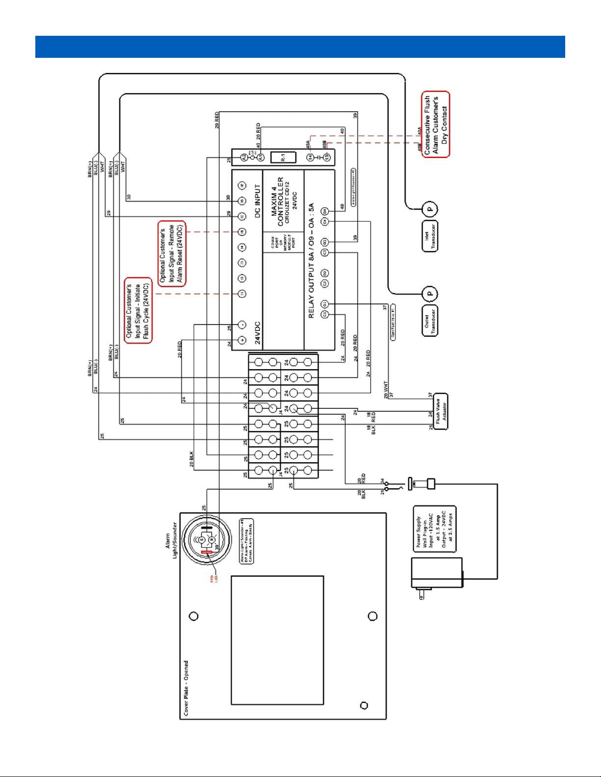
VII. ELECTRICAL CONNECTIONS
NOTE:When using an external power source, the input power to the Controller must be the same as indicated on the
upper leside of the PDA/ATF‐MAX. Typically the controller is 24 volts DC. Plug the provided 24VDC Power Supply into
a standard 120VAC Outlet, observing all state and local codes.
FlushValve
The FlushValveis connected to Output#1 terminal(+ signal, white wire), Common (‐) power termi‐nal (Power Common, black
wire), and 24VDC (+) power terminal (Power +, red wire). PleaseNote‐withpoweronandnosignal,theFlushValvewill
movetoitsclosedposion,unlitisclosed.
PressureTransducers
The PressureTransducershave a three wire connecon, white assigned to the input (IC or ID), blue to the Common (‐) terminal,
and the brown to the 24VDC Power (+) terminal .
CustomerIniatedFlushSignal(Oponal)
The oponal CustomerIniateFlushSignalinput is connected to Input I1. Please Note ‐this signal must be a discrete 24VDC
signal, that references the Common (‐) terminals.
CustomerRemoteAlarmResetSignal(Oponal)
The oponal CustomerRemoteAlarmResetSignalinput is connected to Input IB. Please Note ‐this signal must be a discrete
24VDC signal, that references the Common (‐) terminals.
ConsecuveFlushAlarmOutputSignal(DryContact,Oponal)
Output #4 is the discrete ConsecuveFlushAlarm24VDC output signal, that is connected to the coil of Relay 1 (R‐1). This relay
provides a Dry Contact connecon for Customer ConsecuveFlushAlarmsignal.
Review the Electrical Schemac secon prior to making any connecons to the controller.