Medva HLR240 BAC-1.3 User manual

INSTRUCTION MANUAL
AUTOMATIC GATE MECHANISM
HLR240 BAC-1.3
HLR360 BAC-1.3
Ed2. 27/08/18

Declaration of Conformity
Name or Company Name: Medva Mecanismos del Valles, S.L.
Address: C/ Natación 26-28 Pol. Ind. Can Roses - 08191 Rubí
Tax Identication Number (CIF/NIF): B-60528015
HEREBY CERTIFIES:
That hydraulic equipment HLR240 and R360 has been manufactured to be incorporated into a machine or to be
assembled with other machinery to manufacture a machine in accordance with Directive 2006/42/EC:
Meets the essential safety requirements of the following EEC directives.
2006/95/EC Low Voltage Directive.
2004/108/EC Electromagnetic Compatibility Directive.
Likewise, it declares that the machinery may not be operated until the machine in which it must be incorporated or of which it will be a
component has been identied and declared to comply with the terms of Directive 2006/42/EEC and subsequent amendments.
-We put the CE conformity marking on the machine
Plate number:
It is hereby certied in Rubí, on 24 May 2012
The Managing Director
ANTONIO ORANTES ZAMBRANO
SECURITY WARNING
Risk of crushing
Improper handling of machinery in operaon may pose a risk of injury to ngers and hands. During the installaon
process, extend the rod completely either hydraulically or electrically, and connect the front support manually with-
out electrical connecon. During operaon, avoid any type of handling of the rod, especially if the mechanical stop is
installed.
Electrical hazard
Contact may cause electric shock, so make sure the device is disconnected from the power supply prior to performing
any wiring manipulaon.
Ed2. 27-08-18
1 of 11

GENERAL SAFETY INSTRUCTIONS
SAFETY RULES FOR THE INSTALLER
• WARNING! In order to ensure personal safety, it is important to follow all instructions carefully. Improper installa-
tion or improper use may result in serious personal injury.
• This installation manual is an integral part of the product and must be delivered to the user. Keep this installation
manual and all information material.
• This product has been designed and built exclusively for the use indicated in this manual.
• Any application not indicated could be harmful to the equipment and/or represent a source of danger.
• To ensure proper operation of the mechanism and an adequate degree of safety, use only original spare parts,
accessories and xtures.
• Do not install the device in an explosive atmosphere. The presence of ammable gases or fumes implies a seri-
ous safety hazard.
• The mechanism has a torque and anti-crush controller in the BACN version. However, other safety devices (e.g.,
photocells, sensitive strips, etc.) must also be installed to prevent dangers arising from moving mechanical ac-
tions (crushing, dragging, shearing).
• For each installation it is necessary to use at least one light-signalling device, as well as a sign correctly attached
to the gate structure.
• Installation, electrical connection, adjustments and maintenance of the appliance must be carried out exclusively
by professionally qualied technical personnel. Wrong installation or improper use of the product can cause seri-
ous damage to people or property.
• Always install a dierential with a value of 0.03 A. and a thermomagnetic switch with an opening of the contacts
of at least 3 mm provided with overload and short circuit protection.
• Connect the yellow-green ground cable to the terminal marked with the symbol on the control panel, the safety of
this appliance is guaranteed only when the mechanism is connected to a proper ground installation according to
the applicable regulations.
• The mechanism must not be put into denitive operation before all the connections have been made, the e-
ciency of the safety devices controlled and the pushing force congured to the minimum, in compliance with the
regulations in force concerning automatic doors (Directive 89/392 and standards EN 12453 and EN 12445).
• Ensure gate structure is solid, balanced and suitable to be activated, ensure that the gate does not have friction
points during its movement
SAFETY RULES FOR THE USER
• In case of malfunction, do not attempt to repair and contact a specialist technician.
• Do not allow children or pets to approach the gate. Never let children stand or play with gate controls. Keep re-
mote controls away from children and users who are not authorized to operate them; keep controls where unau-
thorized users or children cannot access them.
• In the event of a power failure or emergency, you must know how to release the gate to be able to manipulate it
manually.
• Please keep these safety instructions. Please make sure everyone who uses or is near the gate is aware of the
hazards related to automatic gates. If you sell the property with the gate mechanism or sell the mechanism sepa-
rately, please provide the new owner with a copy of these safety instructions.
2 of 11
TECHNICAL DATA
MODEL: HLR
3 of 11
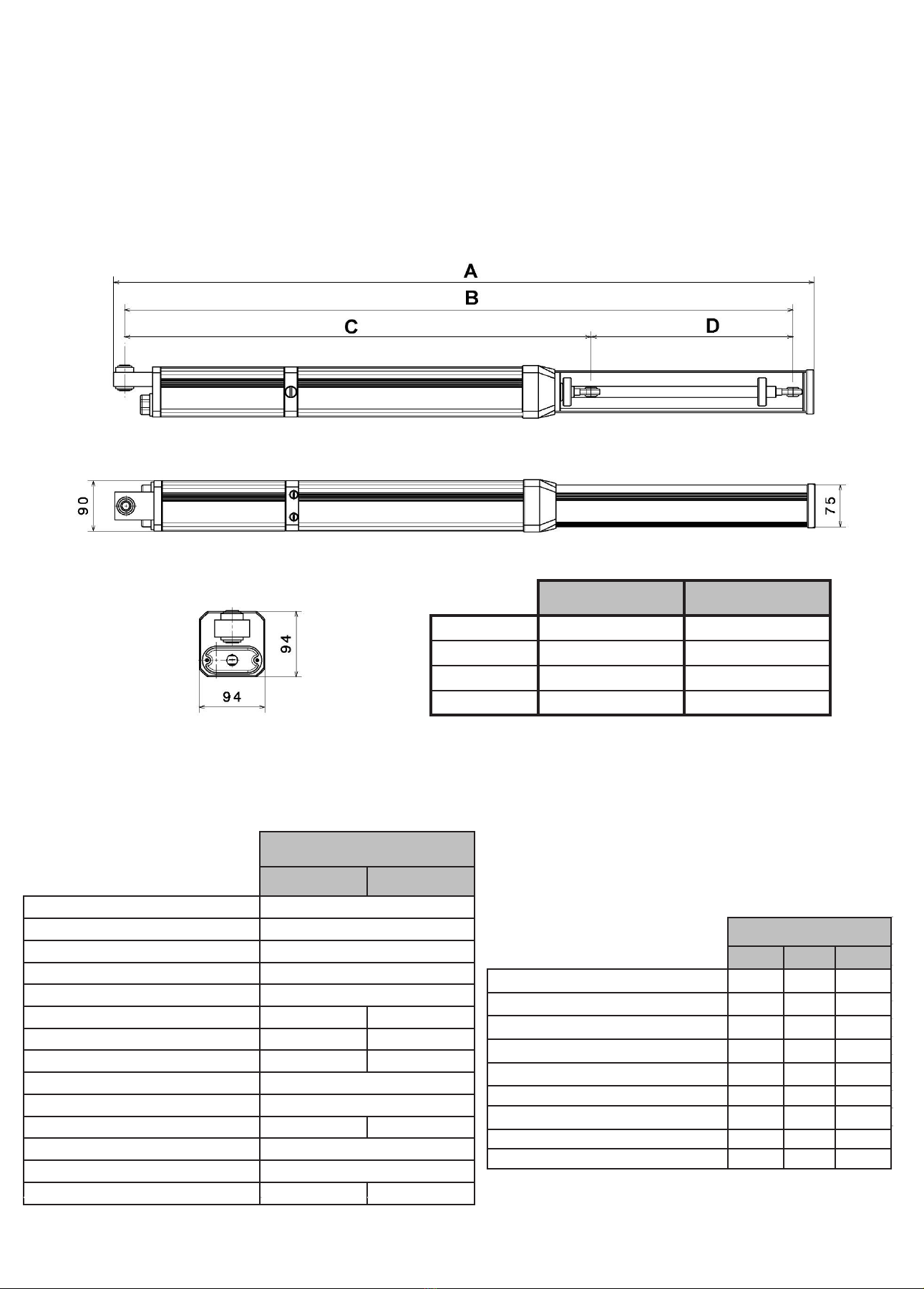
Dimensions HLR240 HLR360
A1050 mm 1290 mm
B952 mm 1192 mm
C710 mm 830 mm
D242 mm 362m/m
TECHNICAL DATA
HLR
240-1.3 360-1.3
Power supply 230 V 50HZ
Motor power rating 276 W
Absorbed consumption 1.3 A
Capacitor 12 uf
Maximum pressure 50 bar
Rod stroke length 242 mm 362 mm
Closing manoeuvre time 20 s 31 s
Opening manoeuvre time 17 s 26 s
Closing force 637 Kg
Opening force 508 Kg
Maximum gate length 4 m 6 m
Temperature range -15 to 80 °C
Thermal protection 100 °C
Group weight 11 Kg 12 Kg
FEATURES HLR
SB BAC BACN
ANTI-CRUSHING ●
HYDRAULIC CLOSURE OUTPUT ● ●
LOCK IN BOTH MANOEUVRES ● ●
LOCK AT CLOSURE ● ●
LOCK AT OPENING ● ●
REVERSIBILITY IN BOTH MANOEUVRES ●●●
WINDPROOF REGULATION ● ●
SOFT STOP AT CLOSURE ●●●
SOFT STOP AT OPENING ●●●
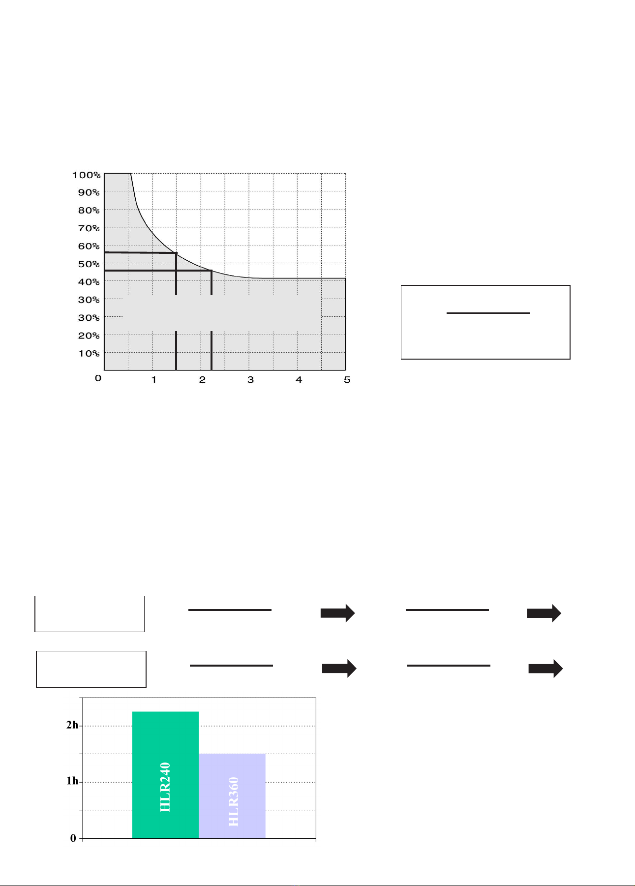
Ta+Tc
%F= x100
Ta+Tc+Tp+Ti
WORK AREA
CALCULATION FOR
HLR240
CALCULATION FOR
HLR360
EXAMPLE MODEL 360
EXAMPLE MODEL 240
(F) Utilisation Factor
USAGE FREQUENCY
The curve allows the calculation of the maximum working time (T) based on the utilisation factor (F).
To ensure proper operation it is necessary to be located inside the work area, shaded in grey.
The tests have been carried out at an ambient temperature of 22 °C; if the motor is at a higher ambient temperature or is
exposed to direct solar radiation, the utilisation factor may be reduced by up to 20%.
Time (Hours)
(T) Time (Hours)
%F: utilisation factor
Ta: opening time
Tc: closing time
Tp: pause time (between opening and closing)
Ti: time between complete manoeuvres
(opening-closing)
Graph.1
Note. To ensure the full closing and opening of the gate, it is necessary to increase the manoeuvring times by 5 sec-
onds.
There are time slots throughout the day, where vehicle trac is very high. Calculations should be made during that
time period.
Example.
What is the maximum working time for a gate that has a pause time of 20 seconds, and a time between full cycles
of 25 seconds?
Ta+Tc
%F= x100
Ta+Tc+Tp+Ti
Ta+Tc
%F= x100
Ta+Tc+Tp+Ti
Graph.2
17+20
%F= x100
17+20+20+25
26+31
%F= x100
26+31+20+25
45.12%
55.88%
CONCLUSION: when we transfer the data obtained to the
graph 1, the maximum usage period for the model 240 is 2h
and 15 min and for model 360 it is 1h and 30 min.
Whenever the dimensions of the gate and the dimensions of
assembly allow, it is advisable to use model 240.
4 of 11

Fig. 2 Fig. 3
Fig..1
ASSEMBLY DIMENSIONS
Important: all dimensions are referenced from the center of the hinge.
*Measurements in millimeters.
5 of 11
MAXIMUM
DIMENSIONS
Max 2 m Max 4 m
Max 6 m
LIGHT
400KG
HLR 240
110°
HLR 240 - 95°
HLR 360 -115°
HLR 360
95°
MEDIUM
600KG
HLR 240
110°
HLR 240 - 95°
HLR 360 -115°
HLR 360
90°
HEAVY
800KG
HLR 240
110°
HLR 360
115°
HLR
OPENING INWARDS (Fig. 2)
M A B C
85° 195 185 90
90° 180 180 90
95° 165 180 90
100° 150 180 90
105° 140 180 90
110° 125 180 90
115° 115 180 90
120º 105 180 90
OPENING OUTWARDS (Fig. 3)
M A B C
85° 200 180 100
90° 180 180 100
95° 165 180 100
100° 150 180 100
105° 125 180 100
HLR
OPENING INWARDS (Fig. 2)
M A B C
85° 130 125 70
90° 120 120 70
95° 110 120 70
100° 100 120 70
105° 93 120 70
110° 85 120 70
115º 85 115 70
OPENING OUTWARDS (Fig. 3)
M A B C
85° 130 120 80
90° 120 120 80
95° 110 120 80
100° 100 120 80
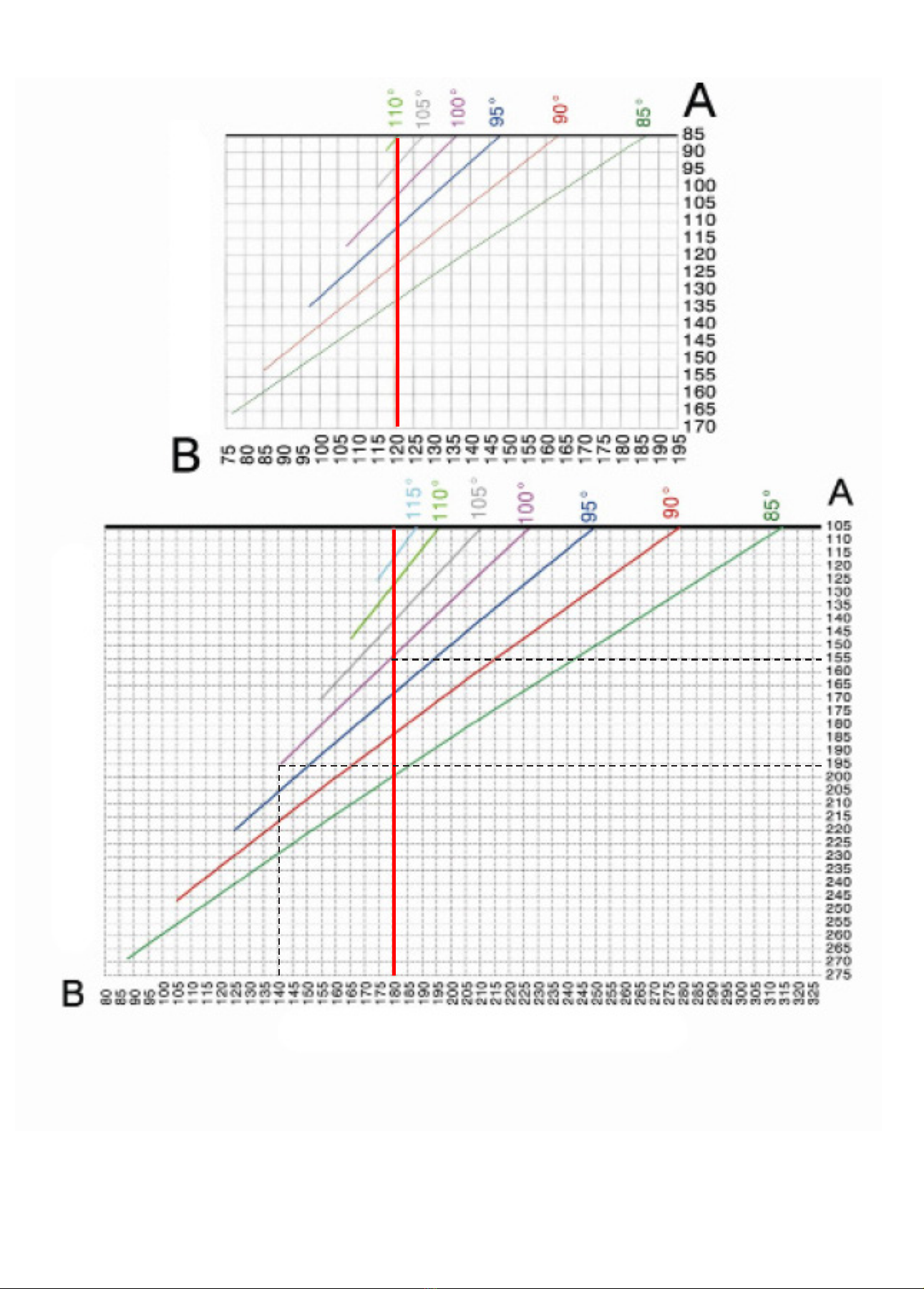
SPECIAL DIMENSIONS OPENING INWARDS (Fig. 2, page 5)
We are occasionally forced to vary the standard dimensions for reasons of space when placing the supports, the above graphs refer to the both
automatic gate mechanism models (240-360) and when the opening is inwards.
The gates' opening degrees are shown at the top of each of the graphs, from these values a cross section line emerges on which dimensions A
and B may be obtained (Fig. 2, page 5). It is important to be as close to the thick vertical line as possible.
Dimension C remain constant in both motors, model 360 C=90 mm and model 240 C=70 mm.
Example: What would be the dimension A and what engine should I use to automate a gate with a 100° opening where B=140 mm? A motor
with a 360 mm stroke length and dimension A=195 mm (see example in graph of assembly dimensions 360 with thick discontinuous line,
special dimension).
Conclusion: We cannot choose model 240 because it goes beyond the positioning limits. The 360 mm stroke length motor allows higher
dimensions than the standard.
6 of 11
ASSEMBLY DIMENSIONS 240 (C=70)
ASSEMBLY DIMENSIONS 360 (C=90)
*Measurements in millimetres.
EXAMPLE (STANDARD)
EXAMPLE (SPECIAL DIMENSION)

ASSEMBLY INSTRUCTIONS
7 of 11
Fig. 1
Fig. 2
Fig. 3
Fig. 4
Fig. 5
Fig. 6
Fig. 7
Fig. 8
Fig. 9
Fig. 10
Fig. 11
Fig. 12
Fig. 13
Fig. 14
Fig. 15

1
2
1. Place the pillar support (Fig. 1, page 7) by trimming or supplementing the support according to A and B dimen-
sions of the table on page 5. Determine the height of the support where the gate has a rigid surface to secure the
front support, taking into account that there is a 15 mm gap between supports (Fig. 1, page 5).
2. In this step we will proceed to the electrical installation of the
device.
Connect the terminals according to the following diagram.
Proceed by extending the rod electrically until the end of its
stroke.
common
GROUND
capacitor
3. Trim or supplement the gate support according to dimension C of the table on page 5. Position the motor wit
the front support, with the rod fully extended (Fig. 2, page 7) and the ball joint threaded to the maximum (Fig. 3,
page 7). With the gate closed balance the motor and with the help of a spirit level (Fig. 4, page 7) mark the posi-
tion of the support on the gate and attach it to the mark made.
4. Assemble the motor and unscrew the ball joint about 3 turns to secure the closure, place the safety ring, insert
the gasket and secure the ball joint with the nut to the support (Fig. 6, page 7).
5. Manually operate the gate and open it about 10° less than the desired position, move the ring at the end of the
stroke on the rod (Fig. 9, page 7) to the telescopic bushing (Fig. 10, page 7) and attach it with the allen screw.
Now we can activate the motor electrically. Reposition the ring if the opening is not as desired.
6. Once the motor is working correctly, proceed to adjust the limiters (Fig. 11, page 7). The limiters are in charge
of controlling the force of the device, and are independent in the opening (blue limiter) and closing (red limiter)
manoeuvres. The screws will be handled with rotations of a maximum of 45°.
Proper force adjustment reduces the risk of damage to the installation and users.
7. Then adjust the soft closing and opening stop (Fig. 12, page 7). This valve is common to control the speed of
the device before completing the closing and opening manoeuvre, avoiding annoying bumping from the door.
The manipulation will be carried out with rotations of a maximum of 10°, if we close this valve completely, the
soft stop is lost (15 mm).
8.Finally, the rod cover (Fig. 13, page 7), the gasket (Fig. 14, page 7) and the case cover (Fig. 15, page 7) will be
press-tted.
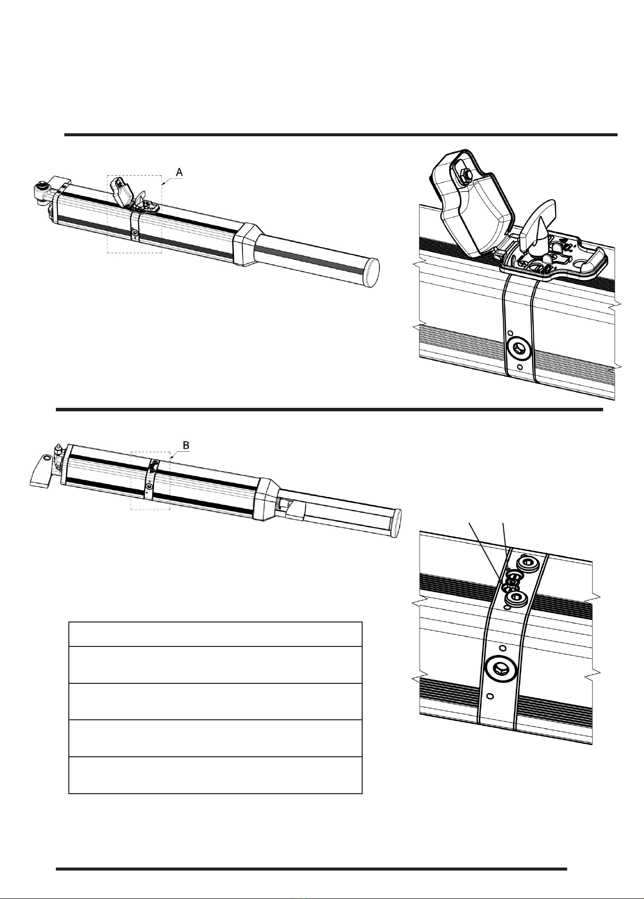
ACTIVATING THE HYDRAULIC LOCK
When the actuation of the door lock is hydraulic, we have to take into account the type of door opening;
- for inwards opening (Fig. 2 of page 5) we
must connect the hose at the output of the 1/8 G
device in position 2.
- For outwards opening (Fig. 3 of page 5) we
must connect the hose in position 1.
8 of 11
EMERGENCY UNLOCKING
This valve allows us to perform the general unlocking to be able to
operate the door manually in the event of a power outage. To move
the door manually, simply turn 360° counterclockwise.
IMPORTANT: If the valve is not tightened (clockwise) the motor
does not run.
BAC AND WINDPROOF SYSTEM
View of the motor from below.
By manipulating the red and blue valve (located in the lower
part), we can select in which manoeuvre we want the gate to be
manually reversible.
The options are:
RED BLUE
View of the motor from below.
LOCKING OPERATION
The BAC system incorporated in the HLR device oers a wide variety of possibilities. Here is how it should
be manipulated to get the most out of its performance.
IMPORTANT: The partial opening of these valves works as an excellent windproof, and the hardness of
the gate may be adjusted with the motor at rest.
The gate requires a lock for gates that are longer than 1.8 m!
9 of 11
USING THE BAC VALVES
Red open - Blue closed
Lock on opening and reversible on closing.
Red closed - Blue open
Reversible on opening and lock on closing
Red closed - Blue closed
Lock on opening and closing
Red open - Blue open
Reversible on opening and closing
2
1
Pressure
switch N.C
Pressure
switch N.C
Photocell
N.C
Limit switch
N.A
Fig.2
1
Control panel
Safety contact
Fig.1
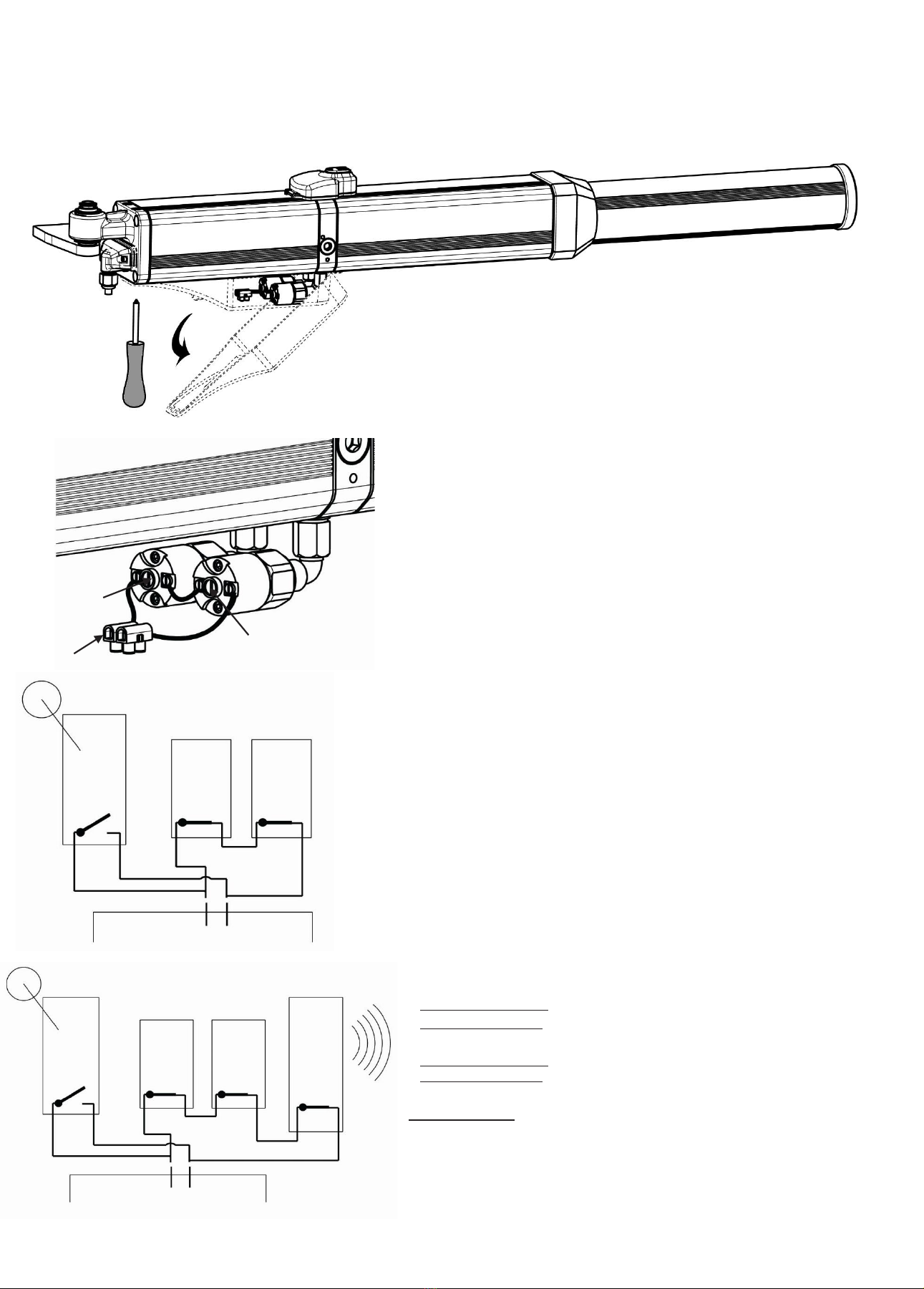
The anti-crush system oers great security throughout the gate's path, both
when closing and opening.
PRESSURE SWITCH CONNECTION.
To access the connection and regulation of the pressure switch remove the
screws located at the rear holding the pressure switch and pull it down as
indicated by the arrow (Fig. 1).
The pressure switch is a normally closed contact (NC), which opens when
the pressure regulated by the adjustment screw is exceeded (Fig. 2, No. 1).
The system consists of two pressure switches (Fig. 2), which are responsi-
ble for controlling the circuit pressure of both manoeuvres independently
when opening and closing. These are connected in series (Fig .3-Fig. 4). The
connection of the pressure switch signal to the control panel is made through
the two-joint strip (Fig.2, No. 2) to the safety contact inlet of the panel. It is
necessary to incorporate a limit switch in the closure, normally open (NO)
as indicated by the diagram in Fig.3. Its function is to override the pressure
switch when the gate reaches the end of its path, and is exercising force on its
frame. Its proper placement is essential to prevent the gate from reversing the
manoeuvre. This will be how the motor will communicate to the control panel
that it can increase the pressure because it has reached the end of its path and
it is not an obstacle that must be released. In order to be able to do without a
limit switch when opening, it is necessary for the panel to have the option that
when the gate is opening and nds an obstacle, reverses the manoeuvre for
one or two seconds so as to release the obstacle and stop. If the panel does not
have this option, we will need to place another limit switch (N.A) in parallel
when opening. In this system, it is essential for the control panel to have an
inhibition of the pressure switch during the start of the closing manoeuvre.
At start-up, the motor requires an increase in force and this option allows an
increase in pressure avoiding an unwanted reversal.
PHOTOCELL CONNECTION
When the control panel does not have an exclusive inlet for the photocell we
can connect it in series with the pressure switches (Fig. 4).
REGULATION
To increase sensitivity, turn it counter-clockwise, and to decrease sensitivity,
turn it clockwise. Turning will be done in 15-degree turns.
Handling the pressure switch according to the type of opening:
-When the door opens inwards (page 5, Fig. 2):
Opening adjustment, Fig. 1 pressure switch A (under the blue limiter)
Closing adjustment, Fig. 1 pressure switch B (under the red limiter)
-When the door opens outwards (page 5, Fig. 2):
Opening adjustment, Fig. 1 pressure switch B (under the red limiter)
Closing adjustment, Fig. 1 pressure switch A (under the blue limiter)
IMPORTANT! It must be handled in accordance with current standard UNE-
EN 12453.
Limit switch
N.A
Fig.3
Control panel
Safety contact
ANTI-CRUSHING SYSTEM
Fig. 4
Pressure
switch N.C
Pressure
switch N.C
10 of 11

*
*BAC system only
BOX CONTENT
SPARE PARTS ACCESSORIES
11 of 11
No. NAME Ref.
9 Unlock cap key 80284
10 Gusset 70141
11 Attachment bag 95008
12 Connection bag 95107
13 Unlock cap set 95138
14 End of stroke stop 95020
15 OILMEDVA-JV oil (1 litre) 70466
16 Ball joint and nut set A232.11003.K1
17 Emergency release key 80687
18 Unused unlock cap key 80858
19 16 µF capacitor 80497
20 Pillar supp. Kit and Gate supp. 240 A232.11001.K1
Pillar supp. Kit and Gate supp. 360 A232.11002.K1
21 Hydraulic lock A232.21002.00
22 Hydraulic hose (in metres) 80736
23 Hose assembly kit A232.22003.K1
No. NAME Ref.
1
HLR240SB A212.11100.00
HLR240BAC A212.11200.00
HLR240BACN A212.11201.00
HLR360SB A212.12100.00
HLR360BAC A212.12200.00
HLR360BACN A212.12201.00
2Installation manual 50208
3Pillar support 240 95006
Pillar support 360 95037
4 Protective cap 70284
5Rod cover 240 70154
Rod cover 360 70163
6 Rod cover cap 70046
7Gate support 240
Gate support 360
95007
95036
8Cable 4x0.75 L1.5m 95036
This manual suits for next models
1
Table of contents
Other Medva Gate Opener manuals

Popular Gate Opener manuals by other brands

Avidsen
Avidsen ZENIA250 quick start guide

GFA
GFA ELEKTROMAT KE 20.24-40,00 installation instructions

Chamberlain
Chamberlain ELITE Series quick start

Chamberlain
Chamberlain LA100 owner's manual

Benninca
Benninca RI.20T operating instructions

DITEC
DITEC entrematic TRAFFIC C Installation manual, maintenance, use

Allmatic
Allmatic MOVEO Series manual

tau
tau R18 series Use and maintenance manual

Merlin
Merlin G900 installation instructions

FAAC
FAAC Estate Slide E-SL 1200 Series instruction manual

Chamberlain
Chamberlain SL 1000-B1 Installation and operation instructions

Mighty Mule
Mighty Mule VEHICLE SENSOR installation manual


