TMT Automation BOXER500E User manual

FOR RESIDENTIAL
USER MANUAL
24V DC MOTOR
SLIDING GATE OPENERS
BOXER500E / BOXER800E


INSTRUCTIONS BOXER500E / BOXER800E SLIDING GATE OPENER USER MANUAL 1
INDEX
1. WARNINGS
2. INSTALLATION
2.1 STANDARD INSTALLATION DEMONSTARTION
2.2 DESCRIPTION OF DEVICE
2.3 DIMENSION OF DEVICE
2.4 INSTALLATION OF MOTOR GEAR AND GEAR RACK
2.5 CHECKING FOR INSTALLATION
2.6 EMERGENCY RELEASE
3. SETUP AND FUNCTION SETTING
3.1 WIRE CONNECTION
3.2 TRANSMITTER MEMORIZATION AND ERASING PROCESS
3.3 SYSTEM LEARNING, RESET PROCESS AND LED DISPLAY
3.4 PROGRAMMABLE FUNCTION SETTINGS
3.5 TESTING AND CHECKING
3.6 SW2/SW6 SETTING
4. TECHNICAL CHARACTERIESTICS
4.1 TECHNICAL DATA SHEET OF SERIES
4.2 H2 PHOTOCELL DATA SHEET
4.3 R1 TRANSMITTER DATA SHEET
4.4 FL2 FLASHING LIGHT DATA SHEET
5. ADDITIONAL INFORMATION
5.1 WIRE CONNECTION OF H2 PHOTOCELL (SAFETY BEAM)
5.2 GREEN BOX INSTALLATION GUIDE
P. 2
P. 3
P. 3
P. 3
P. 4
P. 4
P. 5
P. 5
P. 6
P. 6
P. 7
P. 7
P. 8
P.10
P.10
P. 11
P. 11
P. 11
P. 11
P. 11
P.12
P.12
P.13

2INSTRUCTIONS BOXER500E / BOXER800E SLIDING GATE OPENER USER MANUAL
1. GENERAL PRECAUTION:
WARNING :
This user manual is only for qualified technicians who is specialized in installations and automations.
(1) All installations, electrical connections, adjustments and testing must be performed only after reading and
understanding of all instructions carefully.
(2) Before carrying out any installation or maintenance operation, disconnect the electrical power supply by
turning off the magneto thermic switch connected upstream and apply the hazard area notice required by
applicable regulations
(3) Make sure the existing structure is up to standard in terms of strength and stability
(4) When necessary, connect the motorized gate to reliable earth system during electricity connection phase.
(5) Installation requires qualified personnel with mechanical and electrical skills.
(6) Keep the automatic controls (remote, push bottom, key selectors…etc) being placed properly and away
from children.
(7) For replace or repair of the motorized system, only original parts must be applied. Any damage caused by
inadequate parts and methods will not be claimed to motor manufacturer.
(8) Never operate the drive if you have any suspect with what it might be faulty or damage to the system.
(9) The motors are exclusively designed for the gate opening and closing application, any other usage is
deemed inappropriate. The manufacture should not be liable for any damage resulting from the improper
use. Improper usage should void all warranty, and the user accepts sole responsibility for any risks there
by may accrue.
(10) The system may only be operated in proper working order. Always follow the standard procedures by
following the instructions in this installation and operating manual.
(11) Only command the remote when you have a full view of the gate.
TMT AUTOMATION INC. shall not be liable for any injury, damage, or any claim to any person or
property which may result from improper use or installation of this system.
Please keep this installation manual for future reference.
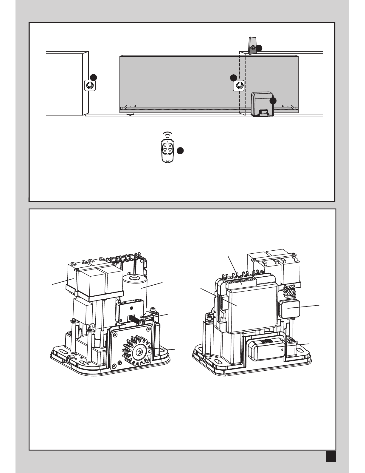
2.1 STANDARD INSATLLATION DEMONSTARATION
1. 24Vdc Sliding motor
2. Transmitter
3. safety photo Sensor
4. Flashing light
2. INSTALLATION:
4
2
1
2.2 DESCRIPTION OF DEVICE
a. Operation gear
b. Limit switch device
c. 24Vdc motor
d. Back-up batteries (Optional)
e. Release device
f. Control panel
g. Terminals of devices
h. Green Box (Optional)
e
h
f
g
a
b
c
d
INSTRUCTIONS BOXER500E / BOXER800E SLIDING GATE OPENER USER MANUAL 3
33

4INSTRUCTIONS BOXER500E / BOXER800E SLIDING GATE OPENER USER MANUAL
2.3 DIMENSTION OF DEVICE
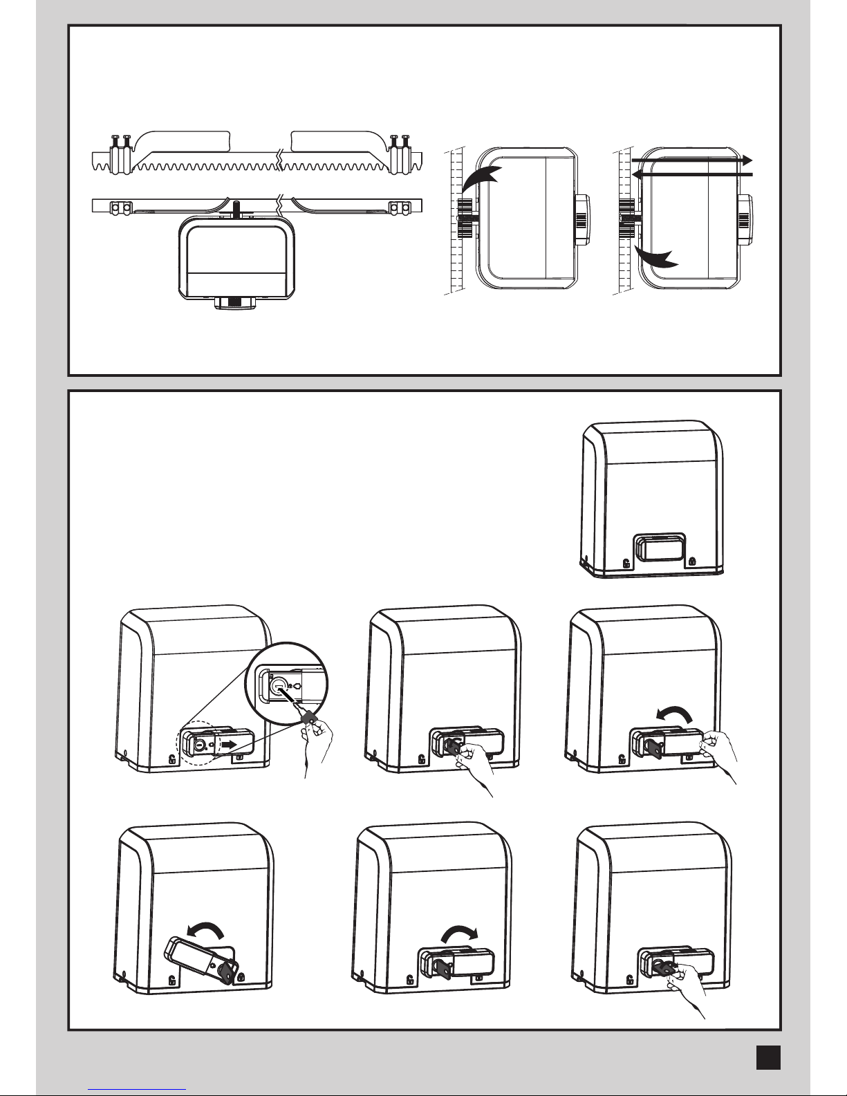
2.4 INSTALLATION OF MOTOR GEAR AND GEAR RACK
>100
25
50>25
INSTRUCTIONS BOXER500E / BOXER800E SLIDING GATE OPENER USER MANUAL 5
2.5 CHECKING FOR INSTALLATION
2.6 EMERGENCY RELEASE
In the case of power failure for emergency release of the motor,
please follow the procedure as below:
Step1. Push the lid of release chamber and move rightward
Step2. Insert the key and turn clockwise to unlock the device
Step3. Turn counter-clockwise of the bar to release the motor
To restore the automation, simply reverse the above procedure.
Step5 Step6 Step7
Step1 Step3 Step4
NO OK
DXSX
Step2

3.1. WIRE CONNECTION
3. Setup and Function Setting:
If the LED display is in normal performing refer to “4.2.1”, you can control the gate by either transmitters or the button
on the board: “UP”-clockwise moving, “SET”- stop and “DOWN”- Counterclockwise moving.
SW1
SW3
SW4
SW5
AC INPUT
1234567891011
1
23456
AC INPUT
1234567891011
1
23456
6INSTRUCTIONS BOXER500E / BOXER800E SLIDING GATE OPENER USER MANUAL
LED2
LED1
AC INPUT
1234567891011121314
1
23456
1 2 3 4 5 6 7 8 9 10 11 12 13 14
Close
Stop
GND
Pb
Ph+
Ph2
Ph1
GND
EXT-
EXT+
GND
+13.75
Light
Open
AC INPUT
1234567891011
1
23456
Green Box Antenna
6
6 7 9
9
6 8 9
6 9
10 11
PB1
PB1, KS1=:
KS1
3 4
FL2
FL2

3.2 TRANSMITTER MEMORIZING AND ERASING PROCESS
3.3 SYSTEM LEARNING, RESET PROCESS, AND LED DISPLAY
(1) To Complete the System Learning:
Step1: Press “SET”; then press “SET” + “DOWN” for 3 seconds, and the LED display shows “LE”
Step2: Press left button (A) on time, the LED display should show “LP”
Step3: The gate goes to Auto-learning, please wait for the learning process to be completed
(2) To Reset Factory Setting:
Press UP and DOWN for 3 seconds, and the LED display shows “CL”
(3) Motor current auto-detection
The LED display shows the current consumption of the motor
"0.4" : During the system learning procedure, the control panel will automatically detect the
current consumption from each motor, indicate the resistance level of the gate whiling the
motor operation. If this reading increase instantly or stay in high reading, please check if
any object in between of the gate moving area, and contact your installer for inspection.
(1) Transmitter Memorizing: Press “RF Learn” button for 2 seconds, and the LED display shows “CS”; then press the transmitter
left button (A); the LED display will blink twice and then be off. The transmitter learning is completed.
(2) Erasing Memory: Press "RF Learn" button for 5~6 seconds as right LED display is on, then wait for LED display off.
LED display
ON
2 Sec
LED display
blink twice LED display OFF
1 3
1314
ON
OFF
LED2
LED1
Press
1~3 Sec
Press
3 Sec
Push
1 2 3
4 5 6
14
LED1
LED2
LED3
ON
OFF
234567891011121314
LED1
LED2
LED3
ON
OFF
Push
3 seconds
12
! CAUTION: Before proceeding to system learning, the transmitter memorizing process has to be completed.
INSTRUCTIONS BOXER500E / BOXER800E SLIDING GATE OPENER USER MANUAL 7
1
1 2
4 5
6
3
23
14
LED1
LED2
LED3
ON
OFF
2

3.4 PROGRAMMABLE FUNCTION SETTINGS
LED Display Definition Function Value Description
Options ofGate
Opening direction
Automatic Closing
There actions of the
photocells / safety edge /
loop detector when they
detecting obstacles
Motor Speed
(% full speed)
The deceleration setting
for gate moving
Deceleration Speed
(% full speed)
Over current setting
1
2
3
4
5
6
7
1-0
1-1
2-0
2-1
2-2
2-3
2-4
2-5
2-6
2-7
2-8
3-1
3-2
3-3
4-1
4-2
4-3
4-4
5-1
5-2
5-3
5-4
5-5
6-1
6-2
6-3
6-4
6-5
7-1
7-2
7-3
7-4
7-5
7-6
7-7
7-8
Clockwise Opening
Counterclockwise Opening
No automatic closing
5 seconds
15 seconds
30 seconds
45 seconds
60 seconds
80 seconds
120 seconds
180 seconds
Please the function setting
after 8
50% Learning Speed
70% Learning Speed
85% Learning Speed
100% Learning Speed
75% of full distance
80%
85%
90%
95%
80%
60%
40%
25%
10%
2A
3A
4A
5A
6A
7A
8A
10A
LED Display Programmable Functions LED Display Programmable Functions
“-L”: The system learning is not done. “LE”: Enter learning mode and then wait for
learning instructions.
“CL”: Reset Factory Setting.
“LP”: The system learning is in progress.
The Auto-learning process of gate moving:
“Gate open to the end- stop close to the
end- stop.”
“OP”: The system is in normal operation To
program, press SET button for 3 seconds,
when the LED display change from OP to 1,
press UP or DOWN to change function
settings (1 to P). Then press SET to enter the
sub function within each group, press UP or
Down to select sub functions and press SET
for confirmation.
8INSTRUCTIONS BOXER500E / BOXER800E SLIDING GATE OPENER USER MANUAL
1. The function can adjust the direction of gate opening.
2. The factory setting is "1-1".
1. This function can cause the gate toclose automatically
after the paused time.
2. The factory setting is "2-2”: 15 Secs as the pause time.
1. Please do the function setting after H & J
2. The factory setting is “3-1”.
1.The function can adjust the running speed of motor.
2.The factory setting is "4-4".
1. The factory setting is “5-1”.
1. The factory setting is “6-4”
1. The function can adjust the running force of motor to
be compatible with the gate weight.
2. The factory setting is "7-5".

INSTRUCTIONS BOXER500E / BOXER800E SLIDING GATE OPENER USER MANUAL 9
LED Display Definition Function Value Description
Open Partially
(Pedestrian mode)
Pre-flashing
Over current reverse
setting
Open-stop-close-stop
function key
Open Partially function
key
External device control
function key
Photocell 1 function
Photocell 2 function
Photocell test function
Stop connector function
8
9
A
C
E
F
H
J
L
P
8-1
8-2
8-3
8-4
8-5
8-6
9-0
9-1
A-0
A-1
A-2
A-3
C-1
C-2
C-3
C-4
E-0
E-1
E-2
E-3
E-4
F-0
F-1
F-2
F-3
F-4
H-0
H-1
J-0
J-1
L-0
L-1
P-1
P-2
3seconds
6seconds
9seconds
12seconds
15seconds
18seconds
The flashing light blinks when
the gate starts to move.
The flashing light blinks 3 seconds
before the gate starts to move.
Stop
Reverse 1 second
Reverse 3 second
Reverse to the end
A key
B key
C key
D key
No function in transmitter
A key
B key
C key
D key
No function in transmitter
A key
B key
C key
D key
Close
Open
Close
Open
Close
Open
Close
Open
1. The function can adjust the time of opening partially.
2. The factory setting is "8-2".
1. The factory setting is "9-1".
1. The factory setting is "A-3".
2. The reverse function only operate 3 times and then stop.
3. If gate reverses, the auto close function will be cancelled.
1. The factory setting is "C-1".
1. The factory setting is "E-2".
1. The factory setting is "F-2".
1. The factory setting is "H-0".
1. The factory setting is "J-0".
1. The factory setting is "L-0".
2. If the function open
1. The factory setting is "P-1".
2. Stt
3.5 TESTING AND CHECKING
Make sure the notices included in 1.1 General safety precaution “WARNINGS” has been carefully observed.
● Release the gearmotor with the proper release key.
● Make sure the gate can be moved manually during opening and closing phases with a force of max.
390N (40 kg approx.)
● Lock the gearmotor.
● Using the Key selector switch, push button device or the radio transmitter, test the opening, closing and
stopping of the gate and make sure that the gate is in the intended direction.
● Check the devices one by one (photocells, flashing light, key selector, etc.) and confirm the control unit
recognizes each device.
Gate Status
Closed
Open
Stop during moving
Closing
Opening
Photocell 2
Stop opening
No effect
Stop opening
No effect
Closes the leaf
Photocell 1
No effect
Open
No effect
Reloads automatic closing time
Reloads automatic closing time
Photocell 1/ Photocell 2
Stop opening
Locks and, on release, reverses to open
Locks and, on release, continues opening
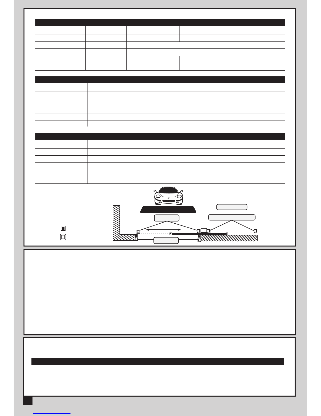
Logic F3-1 The reactions of the photocells when detecting obstacles
Gate Status
Closed
Open
Stop during moving
Closing
Opening
Safety Edge
Stop opening
Stop opening/ closing
Reverses to open for 2 seconds
Reverses to close for 2 seconds
Photocell 1
No effect
Reloads automatic closing time
Open
No effect
Reloads automatic closing time
Logic F3-2 The reactions of the safety edge/ photocell when detecting obstacles
Gate Status
Closed
Open
Stop during moving
Closing
Opening
Loop Detector
Open
Open
Open
Open
Photocell 1
No effect
Reloads automatic closing time
Open
No effect
Reloads automatic closing time
Logic F3-3 The reactions of the loop detector/ photocell when detecting obstacles
● F3 function settings:
● The position of safety devices:
Photocell 1 / Photocell 2
Photocell
Safety Edge
Photocell 1
or
Photocell 1
Loop Detector
Photocell 2
10 INSTRUCTIONS BOXER500E / BOXER800E SLIDING GATE OPENER USER MANUAL
LED1 Photocells
LED2 Photocells
LED1 will be on when the first pair of the photocells are activated.
LED2 will be on when the second pair of the photocells are activated.
LED Indication Descriptions
3.6 RECOGNITION OF LED
4.3 R1 TRANSMITTER DATA SHEET
4.4 FL2 FLASHING LIGHT DATA SHEET
Application
Frequency
Coding
Buttons
Power Supply
Operating Temperature
Dimension
Radio transmitter
433.92Mhz
Rolling code
2, for single-gate or dual-gate operation
3V with one CR2032 button type lithium battery
-20℃~+50℃
71.5mm * 33mm * 14mm
Application
Installation
Operating Temperature
Dimension
For outdoor use
Wall mounted vertically
-20℃~+50℃
85mm * 60.5mm * 40.5mm
4.2 H2 PHOTOCELL DATA SHEET
4. Technical Characteristics:
Detection type
Operating distance
Response time
Input voltage
Operating Temperature
Protection class
Dimension
Through beam
25 meters
100ms
AC/DC 12~24V
-20℃~+60℃
IP54
96mm * 45mm * 43mm
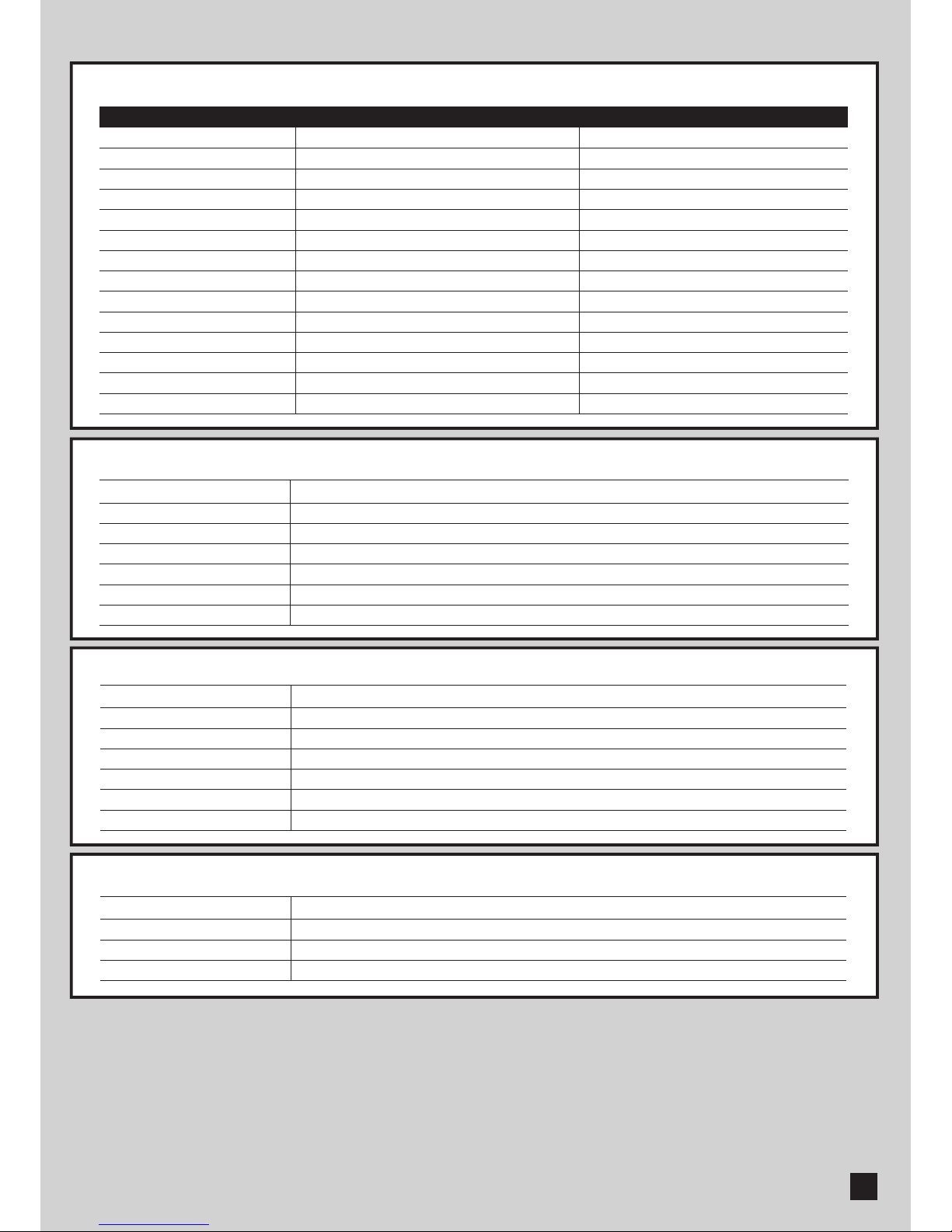
4.1 TECHANICAL DATA SHEET OF SERIES
Worm Gear
5500N
5000N
3800RPM
100W
24 Vdc
3A
Up to 500 KG
6M
5.5A for Maximum 10 secs
-20oC~+50oC
250*170*265mm
8kg
27.10 cm/s
BOXER500E
Worm Gear
8500N
8000N
2600RPM
144W
24 Vdc
3A
Up to 800 KG
8M
5.5A for Maximum 10 secs
-20oC~+50oC
250*170*265mm
9.5kg
18.55 cm/s
BOXER800E
Motor
Gear type
Peak thrust
Nominal thrust
Engine RPM
Absorbed Power
Power supply
Nominal input power
Maximum gate weight
Maximum gate length
Maximum operating current
Operating Temperature
Dimension LxWxH mm.
Weight
Speed
INSTRUCTIONS BOXER500E / BOXER800E SLIDING GATE OPENER USER MANUAL 11
5. Additional Information:
12 INSTRUCTIONS BOXER500E / BOXER800E SLIDING GATE OPENER USER MANUAL
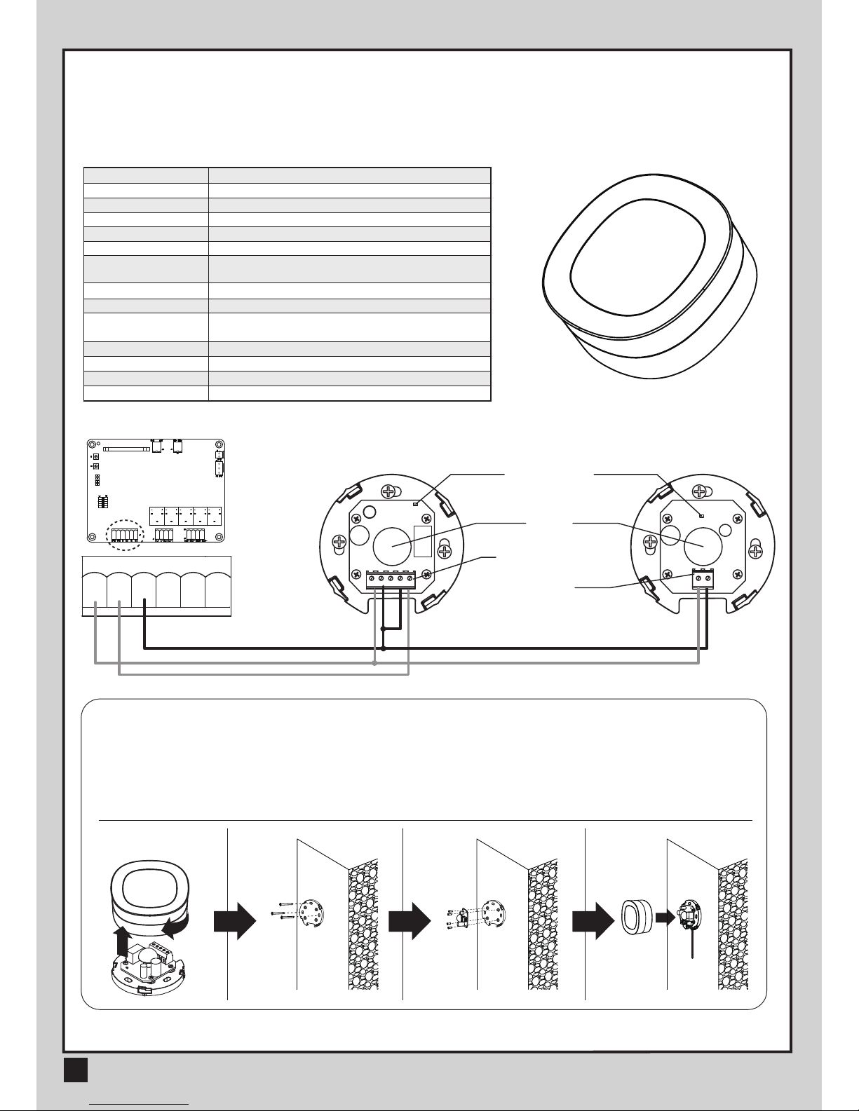
5.1. PHOTOCELL INSTALLATION GUIDE
INSTALLATION:
1. Open the cover and connect wires.
2. Mounted the receiver and transmitter on the proper position.
3. Ensure there are no obstacles between receiver and transmitter.
For optimal efficiency, the receiver and transmitter should be properly aligned.
4. Power-up the photocells and make sure the LED light on receiver and transmitter are ON.
The safety photocells are security devices for control automatic gates. Consist of one transmitter and one
receiver based in waterproof covers; it is triggered while breaking the path of the beams.
G
FO
FH+
Lens
Power LED
Indicator
Terminal Block
Power
Terminal Block
TX
RX
SPECIFICATION:
Step 1 Step 2 Step 3 Step 4
1 2 3 4 5 6 7 8 9 10 11 12 13 14
1 2 3 4 5
COMNCNO
+
-
+
-
1 2
FO1 D SFO+ G G
1 2 3 4 5 6
Detection Method
Sensing Range
Input Voltage
Contact Current
Response Time
Emitting Element
Operation Indicator
Dimensions
Output Method
Current Consumption
Connection Method
Housing Material
Water Proof
Safety Standard
Through Beam
MAX~15m
AC/DC 12~24V
TX: 30mA Max , RX: 25 mA Max
<100mS
Infrared LED/ Wave Length:940nm
RX:Red LED On (beam broken) / Off (beam aligned)
TX:Red LED On
63*63*30 mm
Relay Output
Beam aligned:RX<25ma\TX<30ma
Beam broken:RX <10ma\TX <30ma
Terminal Block
ABS / PC
IP44
CE

INSTRUCTIONS BOXER500E / BOXER800E SLIDING GATE OPENER USER MANUAL 13
OFF ON
Green Box
5+
Cable AC out
AC in
5.2 GREEN BOX INSTALLATION GUIDE
Green Box is for purpose when gate opener is in standby mode to allow it enter the power saving mode.
Installation manner:
AC IN: connect the electricity
AC OUT: connect the power of gate opener, and connect the transformer
5V CABLE: connect 3 pins white socket of control board
Please make sure the switch of Green Box is off before proceeding the system learning and installation of device. Wait
for the system learning and installation of device to be completed, power on the Green Box
Gate opener will enter power saving mode without receiving any instruction in 1 min, and red LED light on Green Box
will be activated. Gate opener start the operation, red LED light and power saving mode will turn off.
CAUTION:
In case of loop or installation of photocell which need power consumption anytime, please do not install Green Box.

14 INSTRUCTIONS BOXER500E / BOXER800E SLIDING GATE OPENER USER MANUAL
34100-XXXX
Low Voltage
24V
24V power supply
for great safety
Durability
Solid material apply
with lasting usage
EZ Instal
Easy installation
and user friendly
interface
Silence
Worm gear application
give silence operation
Manual release device
with easy use and
highly protection
Key Release
This manual suits for next models
1
Table of contents
Other TMT Automation Gate Opener manuals


Popular Gate Opener manuals by other brands

D.A.C.E
D.A.C.E DURASWING Installation and owner's manual

IQ Gate Systems
IQ Gate Systems IntelliSlide IQ-5000-HD Installation and instruction manual

DITEC
DITEC VIVAH OBBI3BFCH quick reference

RIB
RIB SUPER 4000 manual

quiko
quiko Titano QK-T4000 Use and maintenance manual

Beninca
Beninca RI.6SF Operating instructions and spare parts catalogue


