Meerstetter Engineering LTC-1141 User manual
User Manual
LTC-Family
LTC-Family:
LTC-1141
LTC-1142
Meerstetter Engineering GmbH
Schulhausgasse 12
3113 Rubigen, Switzerland
Phone: +41 31 712 01 01
Email: contact@meerstetter.ch
Website: www.meerstetter.ch
Meerstetter Engineering GmbH (ME) reserves the right to make changes without further notice to the product described herein. Information furnished
by ME is believed to be accurate and reliable. However typical parameters can vary depending on the application and actual performance may vary
over time. All operating parameters must be validated by the customer under actual application conditions.
SWISS MADE

Laser & TEC Controller
Software version 0.60
User
Manual
12.04.16 SK
24.08.18 LS
Page 2 ( 8)
5196G
Table of Contents
1LTC Hardware Overview..................................................................................................................................... 3
1.1 LED Status ...............................................................................................................................................3
1.1.1 Power........................................................................................................................................................4
1.1.2 System Core.............................................................................................................................................4
1.1.3 TEC...........................................................................................................................................................4
1.1.4 LDD...........................................................................................................................................................4
1.2 Mounting...................................................................................................................................................4
2Software.................................................................................................................................................................5
2.1 Requirements ...........................................................................................................................................5
2.1.1 Operating System.....................................................................................................................................5
2.2 Installation ................................................................................................................................................5
2.3 Access Over Ethernet...............................................................................................................................5
2.4 Software Description ................................................................................................................................6
2.4.1 Changing Parameters...............................................................................................................................7
2.4.2Resetting Subsystems..............................................................................................................................7
2.4.3 Firmware Update......................................................................................................................................7
2.4.4 Custom Lock Configuration......................................................................................................................7
3Functional Description........................................................................................................................................ 8
3.1 Laser Diode Driver....................................................................................................................................8
3.1.1 Current Modulation...................................................................................................................................8
3.2 TEC Controller..........................................................................................................................................8
4Support.................................................................................................................................................................. 8
Laser & TEC Controller
Software version 0.60
User
Manual
12.04.16 SK
24.08.18 LS
Page 3 ( 8)
5196G
This release of the user manual contains preliminary information and is not yet complete.
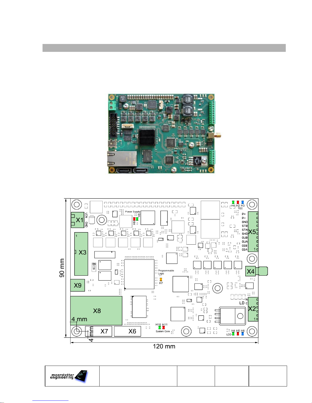
1 LTC Hardware Overview
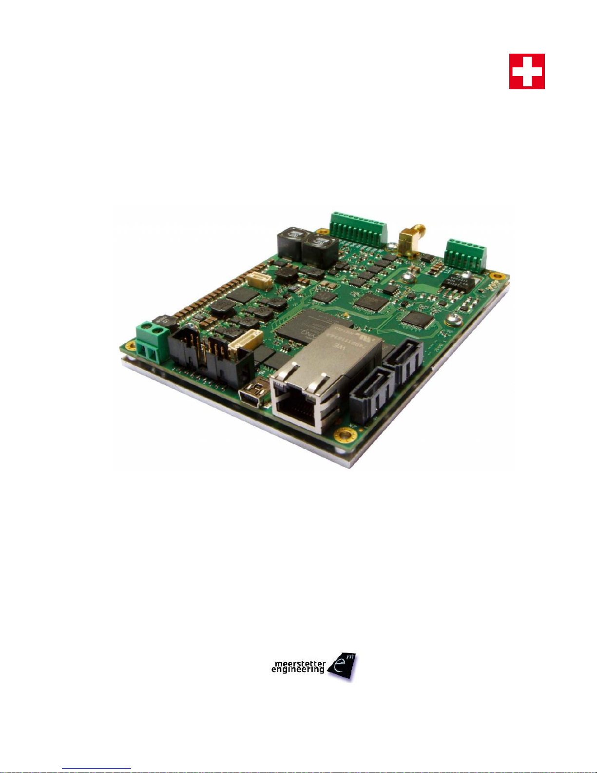
The LTC family controllers are laser diode drivers with an integrated TEC controller (based on TEC-1091).
The core of the LTC controllers consists of a system on chip featuring high performance processing capabilities in
combination with fast ADC, DAC and memory. This allows fast modulation, sampling as well as onboard data
processing.
Object (laser diode, sensor etc.) cooling is managed by the onboard TEC controller featuring high temperature
stability and high measurement precision.
1.1 LED Status

Laser & TEC Controller
Software version 0.60
User
Manual
12.04.16 SK
24.08.18 LS
Page 4 ( 8)
5196G
1.1.1 Power
H8 green steady
Power supply OK
H9 red steady
Power supply failure
H8 green & H9 red steady
System on chip running & at least one power supply rail not ready
1.1.2 System Core
H7 orange steady
Programmable logic starting up
H10 green steady
Initializing
H10 green fast blinking
Run
H11 red steady
Error
H11 red & H10 green steady
Other states:
- Firmware update
- Restart
1.1.3 TEC
H1 green steady
Initializing
H1 green slowly blinking
Ready
H1 green fast blinking
Run
H1 green & H2 red slowly
alternating
System not OK
H1 green & H2 red steady
Restart
H2 red steady
Error
H3 blue slowly blinking
TEC temperature control off (output can be enabled)
H3 blue fast blinking
TEC temperature not stable
H3 blue steady
TEC temperature stable
1.1.4 LDD
H4 green steady
Initializing
H4 green slowly blinking
Ready
H4 green fast blinking
Run
H4 green & H5 red slowly
alternating
System not OK
H4 green & H5 red steady
Restart
H5 red steady
Error
H6 blue steady
Laser Diode Driver run
1.2 Mounting
The LTC controller has to be mounted to a heatsink using four M3 screws, to prevent overheating of the system.
Laser & TEC Controller
Software version 0.60
User
Manual
12.04.16 SK
24.08.18 LS
Page 5 ( 8)
5196G
2 Software
The LTC-114x configuration software allows the setup and monitoring of the controller in a graphical way.
2.1 Requirements
2.1.1 Operating System
The compatibility of the LTC configuration software has been tested with Microsoft Windows 7, 8 and 10.
2.2 Installation
✓Connect the LTC controller using a USB cable with a mini USB-B connector
✓Download the LTC-Family Software Package (.msi).
✓Execute the MSI-file and follow the instructions
Two new icons appear on your desktop: “LTC-114x Configuration Software vX.XX” and “LTC Software vX.XX
Additionals” with further information
The “… Additionals” folder also contains the firmware upgrade file for the LDD Controller itself and some other
useful files..
Info: The MSI setup procedure will also provide you the USB driver and Microsoft.NET files if you do not have the necessary
versions already installed
✓Open the Configuration Software
The Configuration Software displays: “Not connected” because the LTC is not powered by the external power
supply
2.3 Access Over Ethernet
As an alternative to USB, the controller can be connected using an Ethernet connection.
✓Ask your network administrator for the network configuration
✓Connect the controller using the USB connection
✓Configure the IP settings in the communication subsystem (DHCP or static IP address)
✓Remove the USB connection and connect the controller to your LAN using an Ethernet cable
✓Open the menu Tools > Connection Criteria Manager
✓Select the option Use Ethernet (TCP) Connection and enter the IP address of the controller
✓Click Try to connect to a device with these criteria to establish a connection
Now you are able to connect to the controller using the LTC configuration software or connect to the IP address in
your web browser to open the status page.

Laser & TEC Controller
Software version 0.60
User
Manual
12.04.16 SK
24.08.18 LS
Page 6 ( 8)
5196G
2.4 Software Description
The LTC configuration software design corresponds to the hardware layout of the controller. Each subsystem is
divided in a block. Status information is directly displayed in the main window.
Information about subsystems and their configuration can be accessed by clicking on the corresponding field of
each subsystem.
The digital storage oscilloscope (DSO) can be accessed in tphe LDD subsystem by pressing the graph button.

Laser & TEC Controller
Software version 0.60
User
Manual
12.04.16 SK
24.08.18 LS
Page 7 ( 8)
5196G
2.4.1 Changing Parameters
Parameter values can be directly changed by clicking on the text field. An orange indicator is displayed, when a
parameter is not yet stored and active on the controller. Parameters have to be written to the controller by
pressing the enter key. This also applies for selecting options.
By clicking on the orange circle next to the text field, the value can be reset.
2.4.2 Resetting Subsystems
A subsystem can be reset by clicking on the oval status indicator.
2.4.3 Firmware Update
By performing the following steps, the firmware of the controller can be updated to the newest version which can
be found in the software package.
✓Export the configuration of the controller by clicking File > Export Config
✓Open the menu Device > Firmware Update
✓Load the *.mefw file and start the update
✓Reset the device
✓Import the saved configuration by clicking File > Import Config
2.4.4 Custom Lock Configuration
Individual parameter values can be locked so that an end user cannot vary these parameters. The Custom Lock
Settings can be saved using a password. To lock parameters, perform the following steps:
✓Open the Custom Lock Configuration by clicking Tools > Custom Lock Configuration
✓Open the subsystems in which the parameters to lock are located
✓Move the cursor to the desired parameter and set the Lock this setting flag in the tooltip pop-up window
✓To Lock the Firmware Updater open the menu Device > Firmware Update
✓To Lock the TEC Auto Tuning open the Auto Tuning window
✓Click Collect new settings
✓Set a password and click Save and apply
✓For changing the Custom Lock Configuration click Tools > Custom Lock Configuration and type the
password
Hint: This feature is only implemented in the Configuration Software Application. It is still possible to modify a locked parameter by using a self-
made application.

Laser & TEC Controller
Software version 0.60
User
Manual
12.04.16 SK
24.08.18 LS
Page 8 ( 8)
5196G
3 Functional Description
3.1 Laser Diode Driver
The characteristics of the laser diode and the laser diode driver have to be set in the LDD subsystem.
✓Refer to the datasheet of your laser diode to find the parameters forward voltage (VF) and differential
resistance of the laser diode. Add all other resistive components to this value. (E.g. cable resistance) If no
value is specified in the datasheet, use 0.1 Ω
✓Use the Driver Characteristics to limit the output of the driver
3.1.1 Current Modulation
There are two possibilities for the laser diode current modulation as an alternative to the constant current. Either
the internal signal generator can be used or a lookup table can be loaded. The Current Source Selector in the
LDD subsystem defines the source for the modulation.
3.1.1.1 Signal Generator
The signal generator can be accessed in the LDD subsystem. Possible waveforms are:
- Sine
- Rectangular
- Ramp
The amplitude and offset of the current as well as the frequency of the generator can be chosen.
3.1.1.2 Lookup Table
The lookup table has to be defined in an Excel-file (*.xlsx). An example is provided in the LTC Controller Software
vX.XX Additionals..
The lookup table defines the amplitude of the current per sampling point. A maximum of 8192 points can be
defined.
3.2 TEC Controller
Please refer to the TEC-Family User Manual for information about the TEC controller functionality.
4 Support
Please contact Meerstetter Engineering in case of questions.
http://meerstetter.ch/company/techsupport
This manual suits for next models
1
Table of contents


 manual ")