DA1468x Getting Started with the Development Kit
© 2018 Dialog Semiconductor
Figures
Figure 1: The DA1468x ProDK.............................................................................................................. 6
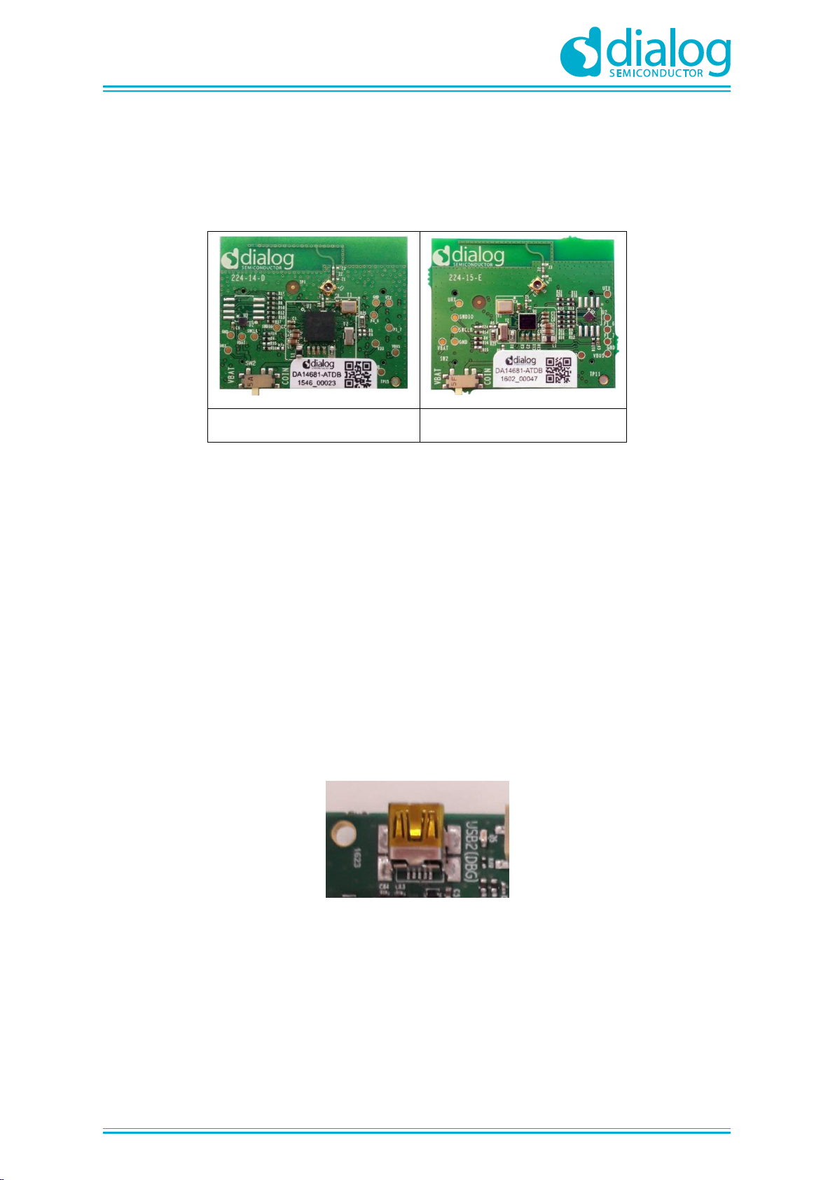
Figure 2: The daughter-boards a) QFN60 and b) WLCSP to combine with the DA1468x ProDK
Development Kit .................................................................................................................................... 7
Figure 3: USB2 (DBG) connector.......................................................................................................... 7
Figure 4: Windows driver installation..................................................................................................... 8
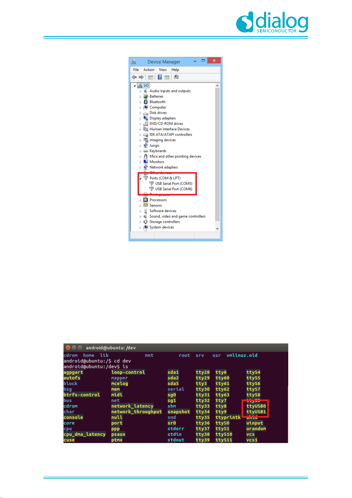
Figure 5: Device Manager Ports............................................................................................................ 9
Figure 6: Ports assigned to ProDK........................................................................................................ 9
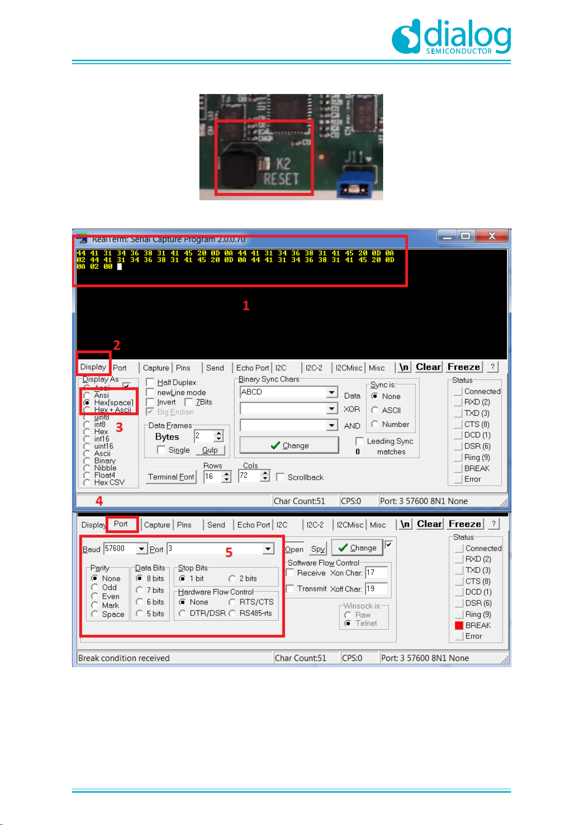
Figure 7: K2 RESET button in ProDK ................................................................................................. 11
Figure 8: Setting port and testing connectivity via RealTerm.............................................................. 11
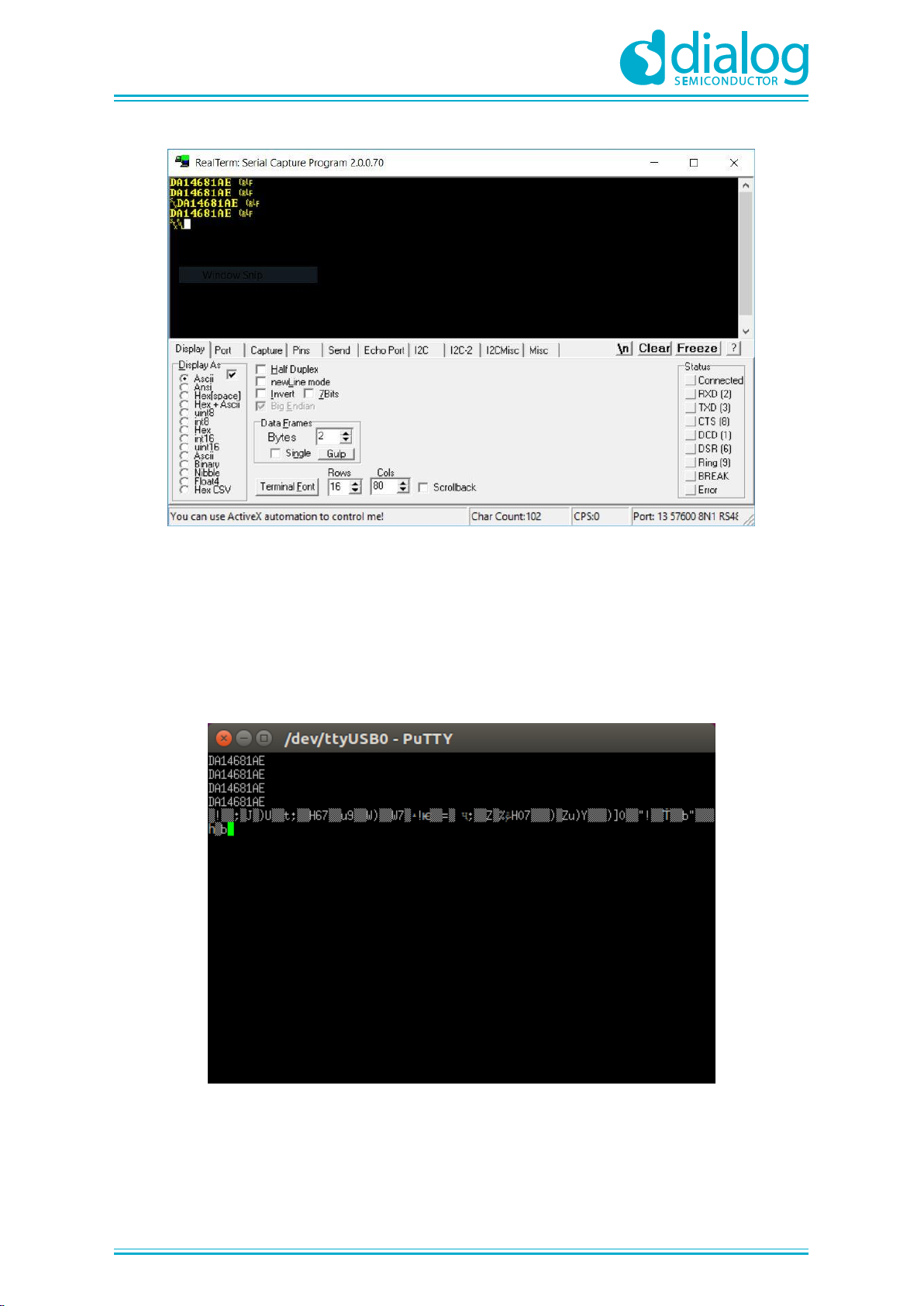
Figure 9: Chip version in RealTerm in Windows................................................................................. 12
Figure 10: Chip version in PuTTY in Linux.......................................................................................... 12
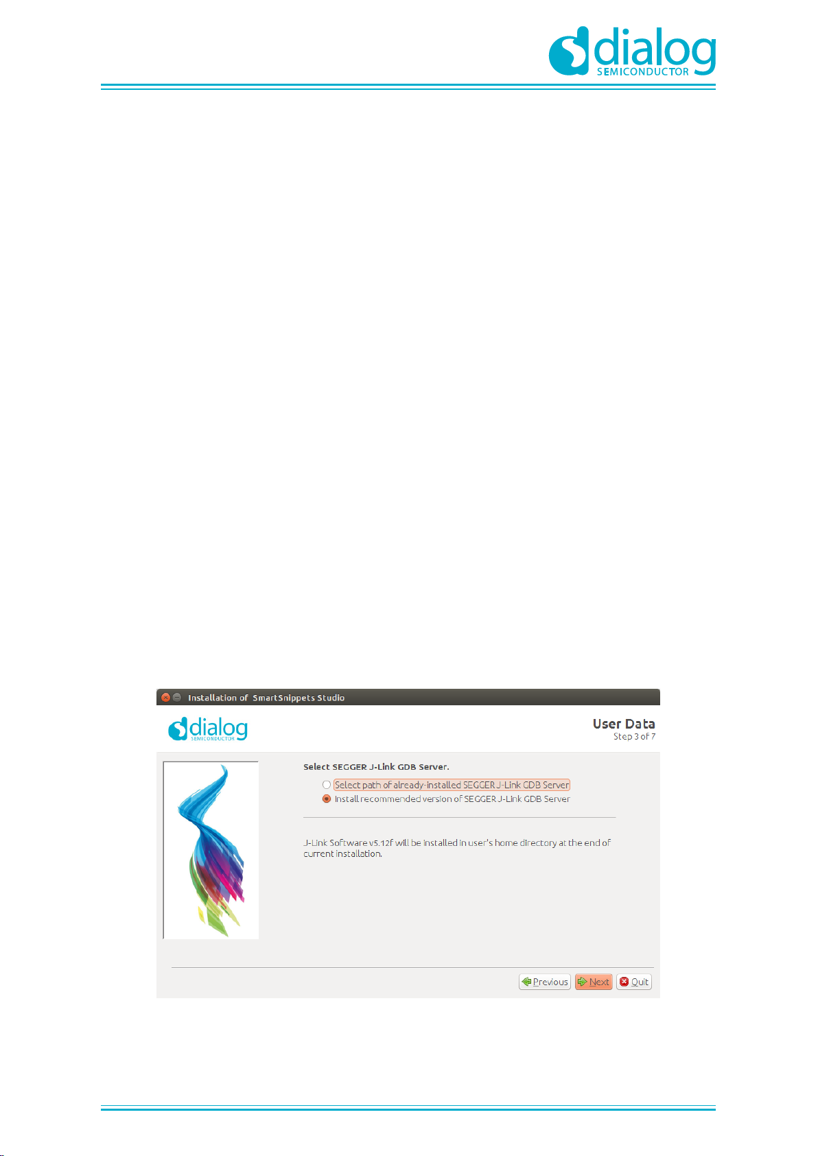
Figure 11: Automatically install J-Link................................................................................................. 14
Figure 12: Select Smart Snippets Studio install directory ................................................................... 15
Figure 13: Tools that require manual installation ................................................................................ 15
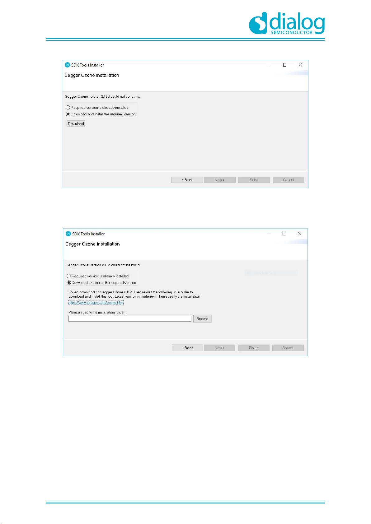
Figure 14: Start Ozone download........................................................................................................ 16
Figure 15: Automatic Ozone download failed...................................................................................... 16
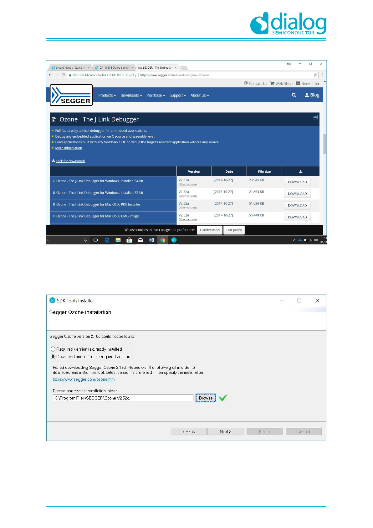
Figure 16: SEGGER Ozone download page....................................................................................... 17
Figure 17: Set Ozone installation directory ......................................................................................... 17
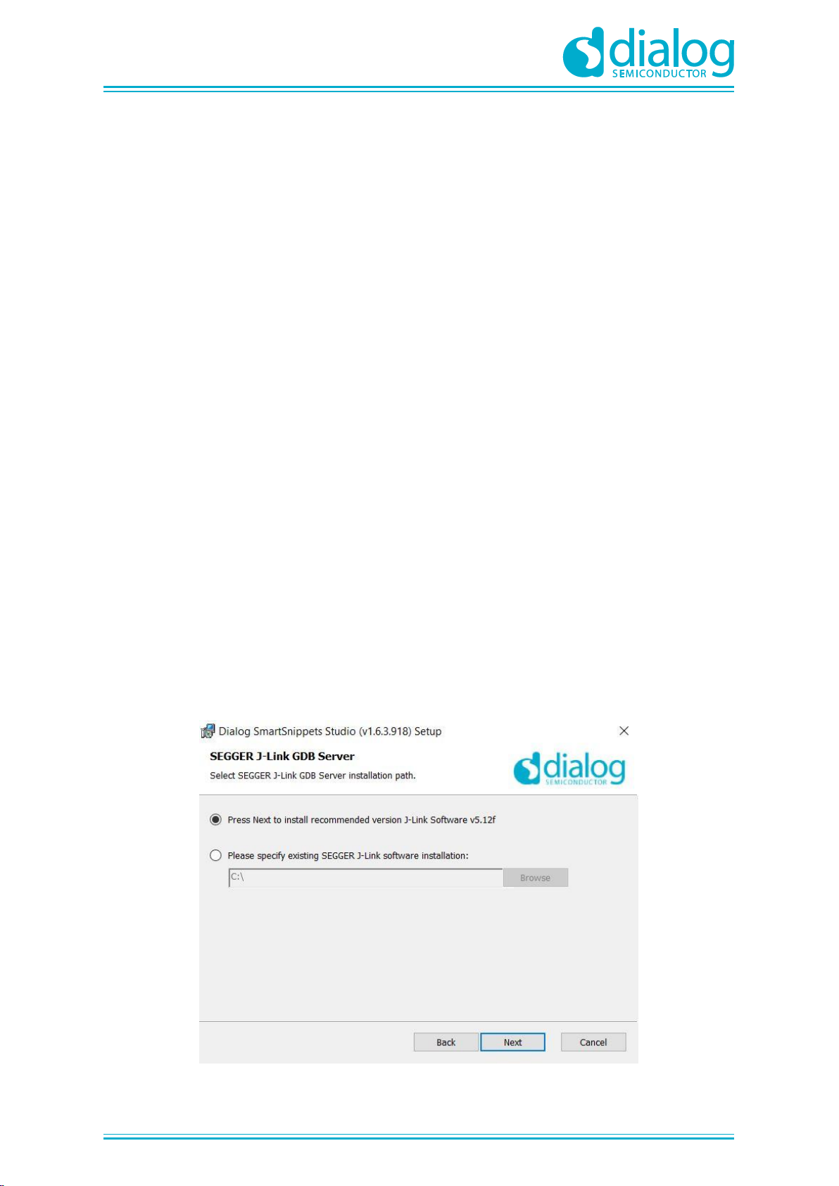
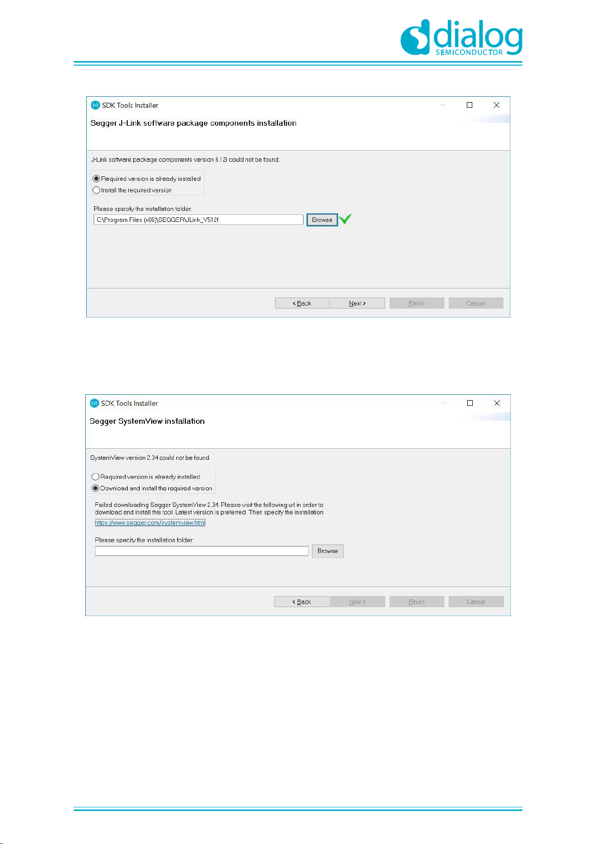
Figure 18: Set J-Link installation directory .......................................................................................... 18
Figure 19: SystemView Download fails............................................................................................... 18
Figure 20: Download SystemView installer......................................................................................... 19
Figure 21: Set SystemView installation directory................................................................................ 19
Figure 22: Automatically install J-Link................................................................................................. 20
Figure 23: Select Smart Snippets Studio install directory ................................................................... 21
Figure 24: Tools that require manual installation ................................................................................ 21
Figure 25: Start Ozone download........................................................................................................ 22
Figure 26: Automatic Ozone download failed...................................................................................... 22
Figure 27: SEGGER Ozone download page....................................................................................... 23
Figure 28: Set Ozone installation directory ......................................................................................... 23
Figure 29: Set J-Link installation directory .......................................................................................... 24
Figure 30: Download SystemView installer......................................................................................... 24
Figure 31: Set J-Link installation directory .......................................................................................... 25
Figure 32: Extract SDK to Workspace (on Windows) ......................................................................... 25
Figure 33: LED D2 on ProDK.............................................................................................................. 28
Figure 34: SmartSnippetsTM Studio welcome page........................................................................... 29
Figure 35: Project import..................................................................................................................... 29
Figure 36: Build Blinky in Release RAM configuration........................................................................ 30
Figure 37: Start Debug in RAM mode ................................................................................................. 31
Figure 38: Build Blinky in Release QSPI configuration ....................................................................... 31
Figure 39: Write Blinky to QSPI Flash................................................................................................. 32
Figure 40: Start Debug in QSPI mode................................................................................................. 32
Figure 41: Executing the Blinky project in Eclipse............................................................................. 33
Tables
Table 1: Parameters for connecting to UART1 ................................................................................... 10
Table 2: Troubleshooting Blinky.......................................................................................................... 34
Codes
Code 1: The main task in SysInit() the prvTemplateTask()................................................................. 27
Code 2: Set function for GPIO............................................................................................................. 28
Code 3: The main routine inside the prvTemplateTask().................................................................... 28