Mega Supply MEg101.3b User manual

MEgA – Měřící Energetické Aparáty, a.s.MEgA – Měřící Energetické Aparáty, a.s.
664 31 Česká 390664 31 Česká 390
Czech RepublicCzech Republic
Uninterruptible power supplies
Supply MEg101.3a and Supply MEg101.3b


Uninterruptible power supplies Supply MEg101.3a and Supply MEg101.3b
3
Uninterruptible power supplies
Supply MEg101.3a and Supply MEg101.3b
1/ CHARACTERISTICS
e uninterruptible power supplies Supply MEg101.3a and Supply MEg101.3b are desi-
gned to supply electrical power to the PQ monitor MEg39 set. eir fundamental part
consists of a HF voltage converter converting the supply voltage into 12 VDC output voltage
with high eciency. When the supply voltage is interrupted, the DC output voltage is de-
livered by the internal rechargeable battery repeatedly for a period of 1 minute. In case of
need, the delivery of electric power at the output of the power source can be blocked up. e
power supplies are equipped with overcurrent protection at their outputs and with a fuse at
the input that is accessible from outside.
2/ TECHNICAL DATA
Input of Supply MEg101.3a
Supply voltage: DC AC, f = 50 Hz
Nominal voltage: 220 VDC 230 VAC
Minimum voltage: 100 VDC 85 VAC
Maximum voltage, continuous: 250 VDC 265 VAC
Maximum voltage, short-term: 300 VDC 300 VAC
Nominal current: 50 mADC 50 mAAC
Maximum current: 150 mADC 220 mAAC
Input power: 15 W / 60 VA
Fuse PO1: FSK001 / 0,5 A-T
Insulation voltage: 4 kVAC
Overvoltage category: CATIII / 300VAC

Měřící Energetické Aparáty
4
Supply MEg101.3b input
Supply voltage: DC
Minimum voltage: 18 VDC
Maximum voltage, continuous: 69 VDC
Nominal current: 750 mADC / 18 VDC
Input power: 15 W
Fuse PO1: FSK001 / 1 A-T
Insulation voltage: 1 500 VDC
Output of Supply MEg101.3a, Supply MEg101.3b
Nominal output voltage: 12 VDC
Output voltage range: 8 VDC to 15 VDC
Maximum output current: 450 mA
Period of secured supply: 1 minute
Guaranteed number of repetitions
of secured supply: 3 times
Maximum full charging period: 10 hours
Starting current inrush: 5 A / 3 msec
Type of internal rechargeable batteries: HR 700 AAA (2 × 5)
Design data
Length × width × height: 108 × 90 × 63 mm
Weight: 0.4 kg
Installation: DIN rail TC 35
Interconnection within the set: HBUS
Terminals,
max. conductor cross-section: 4 mm2

Uninterruptible power supplies Supply MEg101.3a and Supply MEg101.3b
5
Operating conditions
Operating temperature: -20 °C to +50 °C
Operation: in interiors, with cover panel
Protection rating: IP00 / IP20 with covered terminals
Relative humidity: 20 % to 90 %
Altitude: up to 2 000 m
Operating position: arbitrary, preferably horizontal
Safety: EN 61010-1
EMC: EN 61326-1
Degree of pollution: 2

Měřící Energetické Aparáty
6
3/ SYMBOLS USED IN SUPPLY MEg101.3a AND SUPPLY MEg101.3b
User Manual
Caution, electric shock risk
Note in documentation / Warning, risk of hazard
Earth, earthing terminal for HF earthing
IP code Degree of ingress protection
e product is intended for recycling and collection points
Declaration of Conformity – European Community
4/ DESIGN
e uninterruptible power supplies Supply MEg101.3a and Supply MEg101.3b are installed
in aself-extinguishing polycarbonate case with an HBUS connector. e power supplies
are installed onto a DIN rail TC 35 by means of an upper or lower spring-loaded detents.
ey are encased or use the DIN rail cover panel. e HBUS busbar is located between
the case of the power supply unit and the DIN rail. General layout is shown on Fig. 1. Next
to the labels on the cabinet panel, there is the RUN LED, which, when lit, indicates the
presence of 12 VDC output voltage. e terminals with supply voltage and those with output
voltage are located on the bottom side of the unit and their denotations and descriptions are
presented in Tab. 1. e maximum conductor cross-section is 4 mm2. e input fuse PO1
is located in the cap hidden under the screwed-on cover located close to the input supply
voltage terminals.

Uninterruptible power supplies Supply MEg101.3a and Supply MEg101.3b
7
Tab. 1: Terminals of uninterruptible power supplies Supply MEg101.3a
and Supply MEg101.3b
Terminal
number
Terminal
identication
Terminal description
1 GND Common conductor of the PQ monitor and
Supply power unit set
2 STOP Secured output voltage blocking
3 +12 V Secured output voltage +12 VDC
14 HF earthing
16 L
+
AC power supply phase conductor or DC supply voltage
positive pole
18 N
–
AC power supply neutral conductor or DC supply voltage
negative pole
Fig. 1: Supply MEg101.3a unit

Měřící Energetické Aparáty
8
5/ SAFETY INFORMATION
Maximum attention must be paid to the following information.
Warning, warns of circumstances that constitute safety risks for the operator.
Caution, presents conditions and facts that may damage the uninterruptible power
supply units Supply MEg101.3a or Supply MEg101.3b.
• e personnel carrying out installation, putting into operation, maintenance and
removal of Supply MEg101.3a or Supply MEg101.3b power supplies must be equip-
ped and use personal protective equipment to be protected against electric shock as
well as other safety devices.
• e personnel carrying out installation, putting into operation, maintenance and
removal of Supply MEg101.3a or Supply MEg101.3b power supplies must be qua-
lied for working near dangerous voltages. ey must be trained in giving rst aid.
• Only skilled sta may operate the Supply MEg101.3a and Supply MEg101.3b
power supplies.
• e Supply MEg101.3a may be connected to a maximum AC supply voltage of
300 VAC and a maximum DC supply voltage of 300 VDC otherwise there is a risk of
electrical injury.
• e Supply MEg101.3b may be connected to a maximum DC supply voltage of
69 VDC otherwise there is a risk of electrical injury.
• It is necessary to connect protective elements into the supply circuits of the Supply
MEg101.3a and Supply MEg101.3b, refer to Fig. 2.
• e Supply MEg101.3a and Supply MEg101.3b power supplies may only be repai-
red by the manufacturer or by service organizations trained by him.
e Supply MEg101.3a and MEg101.3b power supplies are put into distribution
boards or under cover panels so that the degree of protection for the required envi-
ronment is reached as well as the mechanical impact resistance.

Uninterruptible power supplies Supply MEg101.3a and Supply MEg101.3b
9
6/ INSTALLATION AND COMMISSIONING
When uninterruptible power supplies Supply MEg101.3a or Supply
MEg101.3b are used in a way not intended by the manufacturer, the prote-
ction provided by the power supply may be impaired.
e uninterruptible power supplies Supply MEg101.3a or Supply MEg101.3b may
only be installed by a person authorized for working with input voltages and equip-
ped with personal protective equipment against electrical injury and familiarized
with the operating instructions.
Denotation of supply terminals L and N applies to mains power supply and deno-
tation + and – applies to DC power supply.
e uninterruptible power supplies Supply MEg101.3a and Supply MEg101.3b are always
installed onto DIN rail TC 35. e rails is preferably in horizontal position; the descrip-
tion on the unit panel is readable from left to right.
Wiring of Supply MEg101.3a and Supply MEg101.3b power supplies is shown on Fig. 2.
Fig. 2: Wiring of Supply MEg101.3

Měřící Energetické Aparáty
10
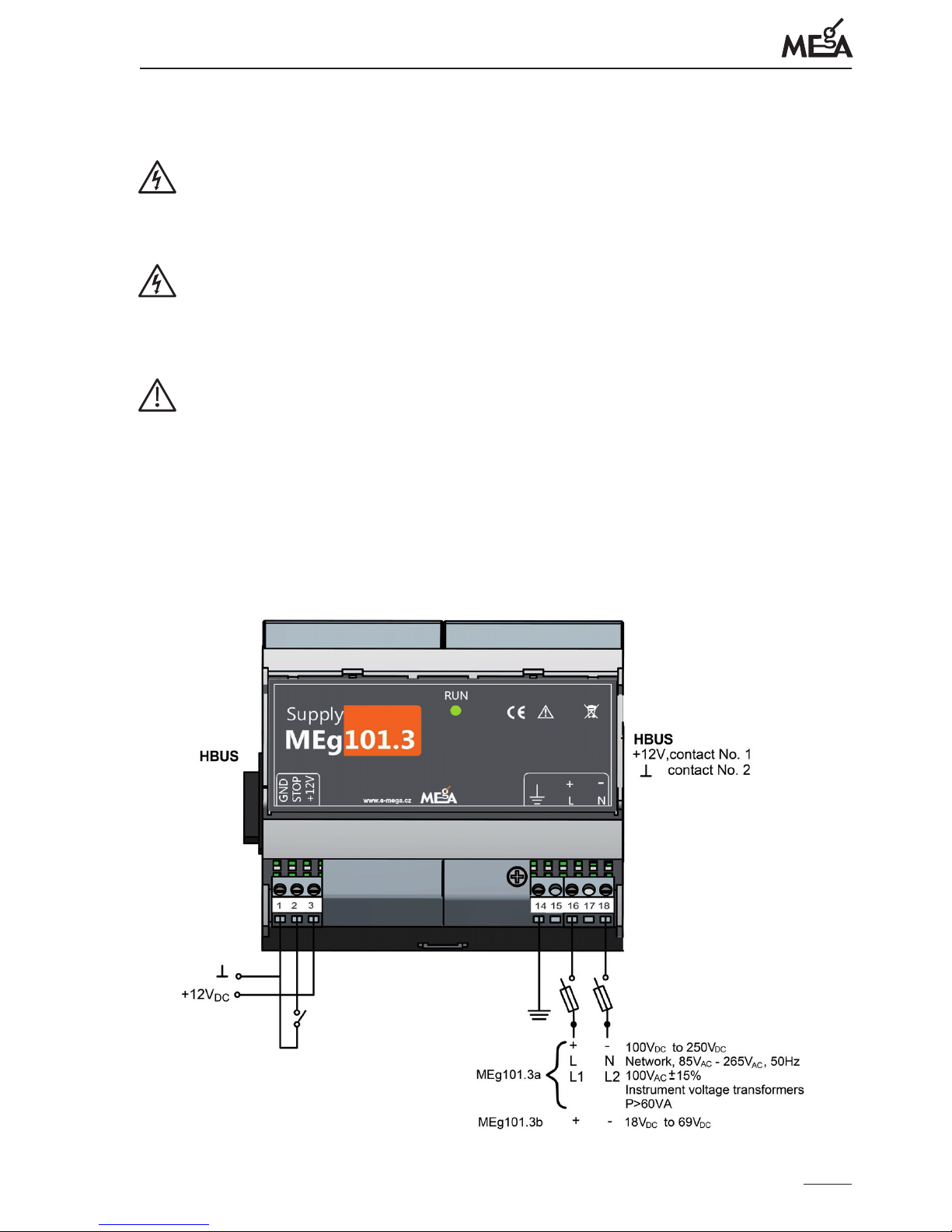
Terminal (14) of the power supply for HF earthing must be connected to the earthing
system at the place where the power supply is installed.
According to the type of the power supply, either AC or DC supply voltage is connected
to terminals (16) and (18) of the power supply.
For supplying with unearthed AC or DC voltage, it is necessary to protect both poles of
the supply voltage with fuses installed in the disconnect switch as shown on Fig. 2.
For supplying with AC or DC voltage with one of the poles earthed, the other pole must
be protected.
e Supply MEg101.3a can support input AC voltage ranging from 85 Vef to 265 Vef with
continuous maximum voltage of 300 Vef and a short-term increase in voltage up to 510 Vef.
e Supply MEg101.3a can support input line-to-line voltage from instrument voltage
transformers with the output of 60 VA and higher.
e Supply MEg101.3a can support input DC voltage ranging from 100 VDC to 250 VDC.
e Supply MEg101.3b can support input DC voltage ranging from 18 VDC to 69 VDC.
e PQ monitor MEg39 set is fed via the HBUS busbar.
When the uninterruptible power supplies Supply MEg101.3a or the Supply MEg101.3b
is used for powering external devices, the uninterruptible output voltage +12 V / max.
450 mA is available on terminals (1) and (3). Terminal (2), when is connected with ter-
minal (1), serves the purpose of blocking the function of uninterruptible voltage supply.
In this way, it is possible to block unnecessary discharging of the internal rechargeable
battery, e.g. during functional checks and inspections.
After connecting the input supply voltage, the LED RUN on the panel lights up and DC
output voltage Un = +12 V appears at the output and the internal rechargeable battery is
charged at the same time. Once the supply voltage is interrupted, the power supply pro-
vides 12 V DC output voltage for 1 minute from internal charged battery. Termination
of the uninterruptible power supply is indicated by the LED RUN going out. With the
internal rechargeable battery fully charged, the power supply is able to supply DC voltage
ranging from 8 V to 15 V at maximum current loading of 450 mA as many as three times
for 1 minute even at the temperature of -20 °C. e recurrence of uninterruptible power
supply is triggered even by a short-time restoration of the input supply voltage.
Even when the power supply is working at maximum capacity, the completely ex-
hausted battery can be recharged in 10 hours.
e uninterruptible power supplies Supply MEg101.3a and Supply MEg101.3b
have an internal voltage source, which is why it is not allowed to remove their covers
while the units are in operation.

Uninterruptible power supplies Supply MEg101.3a and Supply MEg101.3b
11
7/ REQUIREMENTS FOR MAINTENANCE
Within the warranty period, the Supply MEg101.3a or Supply MEg101.3b power
supplies may only by repaired by trained and skilled persons of the manufacturer
or service organization of the manufacturer. Contact information for manufactu-
rer‘s service is given at the www.e-mega.cz webpage.
e Supply MEg101.3a or Supply MEg101.3b must not be exposed to the eects
of chemicals.
e Supply MEg101.3a or Supply MEg101.3b power supply may only be transpor-
ted in their original packaging.
e Supply MEg101.3a and Supply MEg101.3b power supplies have no requirement for
forced cooling. When the power supply is polluted, it is suitable to clean the unit carefully
with a damp cloth without using any cleaning agents.
When the Supply MEg101.3a or Supply MEg101.3b are stored for a long time or
no input voltage has been connected for a long time, the power supply should be
connected to the nominal voltage after 1 year at the latest for at least 10 hours.
It is recommended to carry out preventive inspections every 3 years of operation.
A preventive inspection includes the following:
• checking the power source for mechanical integrity
• checking the magnitude of DC output voltage
• checking the function of blocking the output DC voltage by connecting contacts
(1) and (2) of the power source with disconnected supply voltage
• checking the capacity of the internal rechargeable battery after it has been connec-
ted to nominal supply voltage for at least 10 hours. e power source must provide
DC output voltage to the connected device in three repeated 1-minute intervals,
which are always triggered by a short-time connection of the supply voltage.

Měřící Energetické Aparáty
12
8/ DISPOSAL
After the end of utilization of the Supply MEg101.3a or Supply MEg101.3b, it is neces-
sary to have the power supply recycled in waste collection points according to electronic
waste handling rules. e power source contains a rechargeable battery.
9/ CONTENTS OF THE SET
Basic set
– Uninterruptible power supply MEg101.3a or Supply MEg101.3b
– CD with user description
Optional components of the set
– DIN rail with accessories
– HBUS
– N pcs of FSK 001/0,5 A-T fuse (MEg101.3a)
– N pcs FSK 001/1 A-T fuse (MEg101.3b)
– Single-pole disconnect switch OPVA 10-1
– Double-pole disconnect switch OPVA 10-2

Uninterruptible power supplies Supply MEg101.3a and Supply MEg101.3b
13
10/ WARRANTY
It is not allowed to open the Supply MEg101.3a or Supply MEg101.3b supplies
within the warranty period.
e Supply MEg101.3a and Supply MEg101.3b units are covered by a 24-month warran-
ty counting from the date of purchase, or 30 months at the longest counting from their
expedition from the manufacturer‘s warehouse. Defects demonstrably incurred in this
period due to imperfect construction, imperfect workmanship or unsuitable material will
be repaired by the manufacturer or any other of his service organizations free of char-
ge. During the warranty period, it is necessary to connect the power supply for at least
10 hours to the nominal supply voltage no later than after 1 year.
e warranty becomes null and void, if the user makes unauthorized modications or
changes to the power source, if he connects the supply incorrectly, in case of incorrect
or rough manipulation, or if operated contrary to the given technical terms and user
instructions.
e user will lodge a complaint about defects in the power supply and its accessories
incurred during the warranty period to the manufacturer or the service organization
authorized by him.
e manufacturer is not held accountable in any way for indirect damages caused by
using the MEg101.3a or Supply MEg101.3b power supplies. As a result of the this war-
ranty, the manufacturer is in no way liable for a sum that would exceed the price of the
power supply unit.
11/ MANUFACTURER
MEgA – Měřící Energetické Aparáty, a.s.
664 31 Česká 390, Czech Republic
tel. +420 545 214 988
e-mail: mega@e-mega.cz
www.e-mega.cz

Měřící Energetické Aparáty
14


MEgA – Měřící Energetické Aparáty, a.s.
664 31 Česká 390
Czech Republic
www.e-mega.cz
Edition: 9/2014
Uninterruptible power supplies
Supply MEg101.3a and Supply MEg101.3b
This manual suits for next models
1
Table of contents