MegaGuard ProPlus SG9265064 User manual

SG9265064
INSTRUCTION MANUAL

EC CONFORMITY
Unit SG9265064 conform to EC directives EMC - 2014/30/EU the
following harmonized standards are in use EN 60204-1, EN 61000-6-1, EN
61000-6-3.
SAFETY INSTRUCTIONS
ATTENTION: this instrument generates a 100V, 250V or 500V measuring
voltage on the two external probes.
The current is limited to 1mA and cannot make any injury to the operator.
For operator’s security, avoid to touch the electrodes directly.
Conforms to EN61010-1.
WARRANTY
This unit is guaranteed against all defects due to faulty materials and
workmanship, within 12 months from the date of purchase.
A use not conforming to what specified might be dangerous to the safety of the
operator and may damage the instrument.
In such circumstances the manufacturer is relieved of any liability and the
warranty itself will decay.
REPAIR
Repairs have not been attempted by anyone other than authorized repair
distributors.
Do not try to repair the unit by yourself.
ATTENTION: Dangerous voltage is present inside the instrument.
Protecting the environment
Separate collection. This product must not be disposed of with normal
household waste.
Should you find one day that your product needs replacement, or if it is of no
further use to you, do not dispose ofit with household waste. Makethisproduct
available for separate collection.
Separate collection of used products and packaging allows materials to be
recycled and used again.
Re-use of recycled materials helps prevent environmental pollution
and reduces the demand for raw materials.
Local regulations may provide for separate collection of electrical
products from the household, at municipal waste sites or by the
retailer when you purchase a new product.

TECHNICAL FEATURES
The MegaGuard ProPlus multi-voltage high resistance meter is a portable,
accurate, and versatile instrument designed to measure resistance between two
points, surface to ground, and surface resistivity as defined in IEC61340-5-1.
Graphic liquid crystal display 128x64 pixel, 68x51mm
Measuring range:
10V - from 1kΩ to 50GΩ
100V - from 100kΩ to 1TΩ
250V - from 500kΩ to 1TΩ
500V - from 1MΩ to 1TΩ
Accuracy:
10V - ±5% ±0.6% per GΩ
100V - ±5% ±0.6% per GΩ
250V - ±5% ±0.65% per GΩ
500V - ±5% ±0.03% per GΩ
the value of the measure is always displayed with 3 significant figures
Accuracy of measuring voltage:100V ±5% (Rmeasure > 300KΩ)
250V ±5% (Rmeasure > 2MΩ)
500V ±3% (Rmeasure > 5MΩ)
Humidity Range : to 95%RH
Resolution: 0.1%RH
Accuracy: ±2%RH(@ 25°C, 10%RH~90%RH)
±3%RH(@25°C, 1%RH~10%, 90%RH~95%)
Temperature Range : . . . . . . . . . . . . . . . . . . . . . . . . . . . . . . . . . -20°C to +60°C
Resolution: . . . . . . . . . . . . . . . . . . . . . . . . . . . . . . . . . . . . . . . . . . . . . . . . . 0.1°C
Accuracy: . . . . . . . . . . . . . . . . . . . . . . . . . . . . . . . . . . . . . . . . . . . . . . . . . ±1°C
Batteries: . . . . . . . . . . . . . . . . . . . . . . . . . . . . . . .6 stylo, 1,5V IEC type LR6
Battery life: . . . . . . . . . About 1500 measurements (15 seconds max) at 500V
LOW BATTERY = Blinking
During Low Battery condition only the 10V measurements are allowed.
Auto Shut-off after 5 minutes of inoperativity
Dimensions: . . . . . . . . . . . . . . . . . . . . . . . . . . . . . . . . . . . . . . 243x130x60mm
Weight: . . . . . . . . . . . . . . . . . . . . . . . . . . . . . . . . . . . . . . . . . . . . . . . . . 650g

PROBES AND ACCESSORIES
SG9265063: MegaGuard ProPlus meter with 2 shielded cables, batteries and case
SG9265064: MegaGuard ProPlus complete kit including meter, 2 shielded probes
2 shielded cables, batteries and case
SG9265065: Shielded probe 63mm / 2,3Kg, with two 4mm sockets
and one BNC socket
SG9265070:Concentric ring probe, one BNC socket, three 4mm sockets
SG9265047: Flat shielded probe, with two 4mm sockets
DISPLAY
MEASURED
RESISTANCE
MEASURING
VOLTAGE STABLE
READING
KEYBOARD
TEMPERATURE HUMIDITY
BATTERY LEVEL
To enter the programming mode
To increase the measurement voltage
To move to the previous menu while in programming mode
To display the measured resistance in natural or exponential format
To advance the cursor while in programming mode
To decrease the measurement voltage
To move to the next menu while in programming mode
To turn on / off the instrument and to exit programming mode
To make the measurement
To increase the value at the cursor location when you are in
programming mode

FRONT PANEL
SIGNAL shield
SIGNAL input
HV input
HV shield
BATTERY REPLACEMENT
•Open the battery cover .
•Replace the battery (only alcaline type).
•Close the battery cover.
. . . . . . . . OPERATIVE INSTRUCTIONS
ON / OFF
In order to light-up MegaGuard ProPlus press .
To shut-off MegaGuard ProPlus keep pressed the same key for 1 second
MEASURING VOLTAGE SETUP
Measuring voltage can be setted to 10, 100, 250, 500V
Then there is the mode 10 / 100V (auto) in which the instrument measures at:
10V when Rx <100KΩ
100V when Rx >100K
Ω
HV SIG

Press and hold the button for 1 second to increase the voltage
measurement.
Press and hold the button for 1 second to decrease the voltage
measurement.
Choose the most appropriate voltage depending on the resistance value being
measured and according to the IEC61340-5-1 regulation for the ESD.
DISPLAY FORMAT
The reading on the display can be setted in natural or exponential format:
NATURAL FORMAT EXPONENTIAL FORMAT
Press the button
for 1 second to switch from one format to another.
MEASUREMENT
Hold down the key Wait until the measurement is stabilized (acheck box
at the right of the measured voltage indicates it).
Even if the measure stabilizes within seconds the regulation requires to wait at
least 15 seconds for higher resistances.
Releasing the key the value of the measurement made stay displayed
and can be stored in memory (see next paragraph).
. . . . . . . . . . . . PROGRAMMING
Press and hold the button for 1 second to enter the programming
mode.

The menu of programming are 4:
- MEM
- ALARM
- ° C / ° F
- CONTRAST
Press the button
to move to the next menu.
Press the button
to move to the previous menu.
Press the button to exit programming mode.
MEM
Menu of memory where you can store the data of 100 measures (from MEM 00
to 99 MEM)
The data stored for each measurement are:
- Resistance value
- Voltage used for the measurement
- Humidity detected during measurement
- Measured temperature during measurement
Press the button
to advance the cursor
Press the button to execute the command
Available commands are:
UP to switch to the next memory cell
DOWN to switch to the previous memory cell
STORE to store in the memory cell the measurement made
CLEAR to delete the data of the current memory cell or of all the memory cells
(the choice between the two options is required immediately after the command)
NOTE: during the selection of the memory cell to be read or edited you can hold
down the "MEASURE" pushbutton to move quickly to 10 cells at a time
(10-20- 30 etc.)

ALARM
Alarm menu where you can set an audible alarm sounds when the resistance
measurement is below or above a certain threshold.
Press the button to advance the cursor
Press the button to increase the digit of the cursor.
° C / ° F
Menu for setting the unit of temperature measurement:
- ° C degrees Celsius
- ° F degrees Fahrenheit
Press the button
to switch from one format to another.
DISPLAY
Menu for setting the contrast of the LCD display (0 to 9)
The default contrast is 5.
Press the button
to increase the value of contrast.
POINT TO POINT MEASUREMENT
Point to Point Measurement Rs with 2 Measuring Probes according to IEC
61340-5-1 for measurements of working surfaces, storage racks, transport
boxes, etc

Test Surface
•Be sure that the surface under test is clean and free of grease or other chemicals
than can create an isolant layer.
•In case of doubt clean the surface with a specifical detergent, without alcohol or
silicon, so that the non conductive layer will be removed.
•Place the 2 probes (SG9265065) on the test surface.
•Select the measuring voltage according the resistance value:
Vtest: 10V for Rs :: 105Ω
100V for 105Ω< Rs :: 1012Ω
•Press the central red pushbutton, and keep it pressed until the reading is
complete.
•Continue to keep the button pressed and wait until the reading will be stable,
settling time is higher for high resistance values, for resistances over 1GΩyou
have to wait at least 10 seconds.
MEASURING WITH NON-SHIELDED PROBES
Insert the COAX/BANANA adaptor on the shielded cable as in the picture below:
Vtest
SIGNAL
SHIELD
SHIELD

Test Surface
HV SIG
HV
Vtest
SIGNAL
SHIELD
SHIELD

MEASURING RESISTANCE TO GROUND
Measuring Resistance to Ground according IEC61340-4-1 for measurements at
flooring systems, table mats, chairs etc.
Object under test
•Place the probe (SG9265065) on the test point.
•Select the measuring voltage according the resistance value:
Vtest: 10V for RG:105Ω
100V for 105Ω< RG:1012Ω
•Press the central red pushbutton, and keep it pressed until the reading is
complete.
•Continue to keep the button pressed and wait until the reading will be stable,
settling time is higher for high resistance values, for resistances over 1GΩyou
have to wait at least 10 seconds.
HV SIG
HV
Vtest
SIGNAL
SHIELD
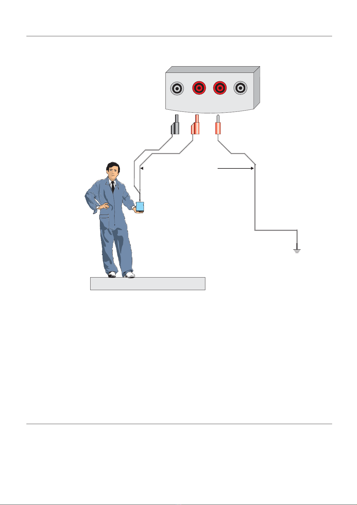
MEASURING RESISTANCE THROUGH A PERSON TO GROUND
Measuring Resistance through a Person to Ground according IEC61340-4-5/NP
for the measurement of a resistance through the combination of a person /
shoes / flooring system .
System under test
•Place the probe (SG9265065) on the operator's hand.
•Select the measuring voltage according the resistance value:
Vtest: 10V for RG:105Ω
100V for 105Ω< RG:1012Ω
•Press the central red pushbutton, and keep it pressed until the reading is
complete.
•Continue to keep the button pressed and wait until the reading will be stable,
settling time is higher for high resistance values, for resistances over 1GΩyou
have to wait at least 10 seconds.
MEASURING SURFACE RESISTANCE Rs
Measuring Surface Resistance Rs of Packaging Materials with a Ring Probe in
compliance with IEC 61340- 5- 1 for the measurement of conductive
(dissipative) packaging materials.
•Be sure that the surfaceundertest isclean andfreeof grease or otherchemicals
than can create an isolant layer.
HV SIG
SHIELD
HV
Vtest
SIGNAL

•In case of doubt clean the surface with a specifical detergent, without alcohol or
silicon, so that the non conductive layer will be removed.
•Place the concentric ring probe (9265.070) on the surface under test.
•Select the measuring voltage according the resistance value:
Vtest: 10V for Rs: 105Ω
100V for 105Ω< Rs: 1012Ω
•Press the central red pushbutton, and keep it pressed until the reading is
complete.
•Continue to keep the button pressed and wait until the reading will be stable,
settling time is higher for high resistance values, for resistances over 1GΩyou
have to wait at least 10 seconds.
Material under test
MEASURING VOLUME RESISTANCE Rv
Measuring Volume Resistance Rv with 1 cylindrical probe and a counter-
electrode according IEC61340-5-1 for measuring the volume resistance of
materials
•Place the counter-electrode (9265.047) under the material .
•Place the probe (9265.065) over the material .
•Select the measuring voltage according the resistance value:
Vtest: 10V for Rv:105Ω
100V for 105Ω< Rv: 1012Ω
(red)
Vtest
HV
(black)
SHIELD
CONCENTRIC
RING PROBE
SG9265005
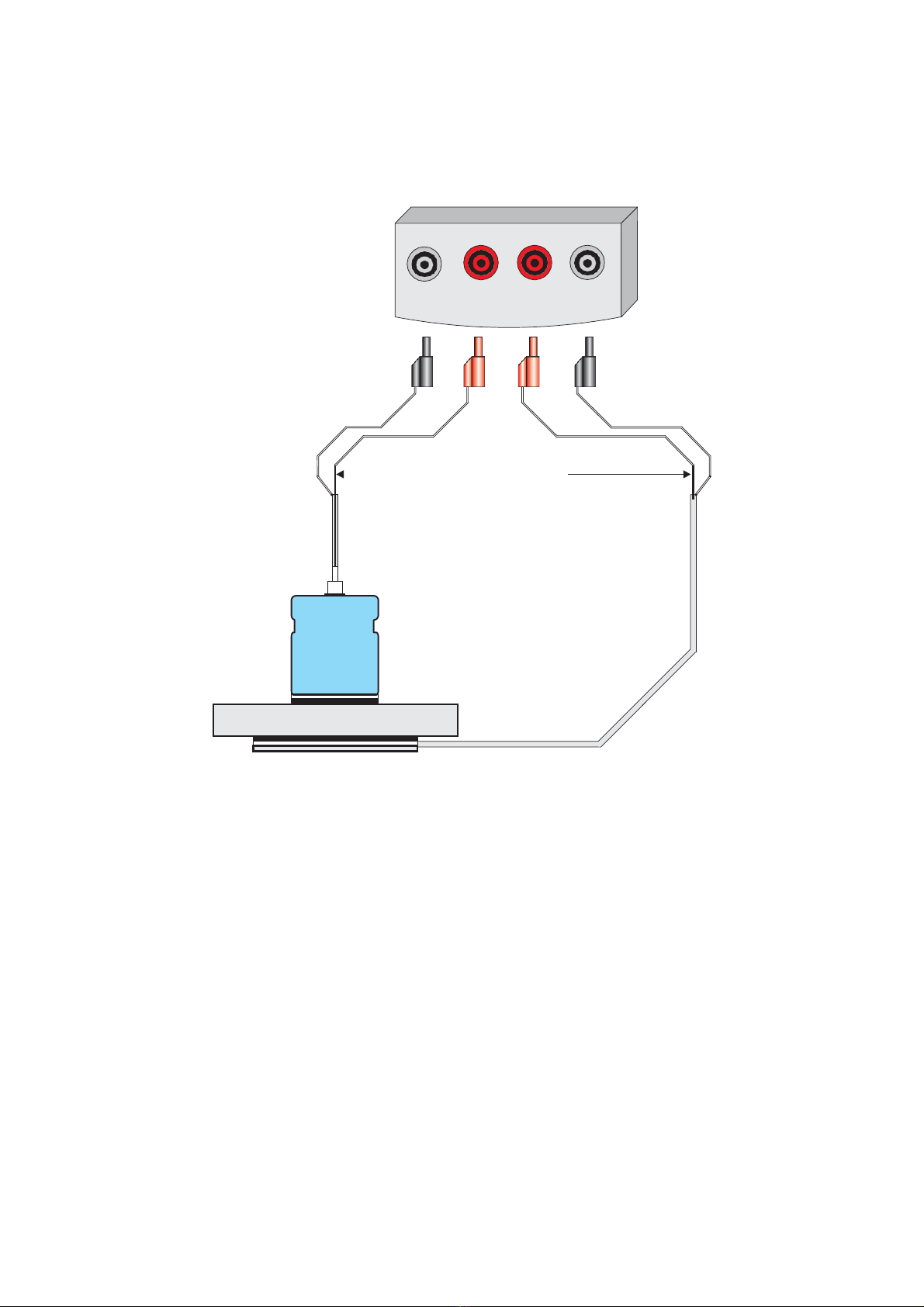
•Press the central red pushbutton, and keep it pressed until the reading is
complete.
•Continue to keep the button pressed and wait until the reading will be stable,
settling time is higher for high resistance values, for resistances over 1GΩyou
have to wait at least 10 seconds.
SHIELD
Material under test
HV SIG
HV
SHIELD
Vtest
SIGNAL
Table of contents


