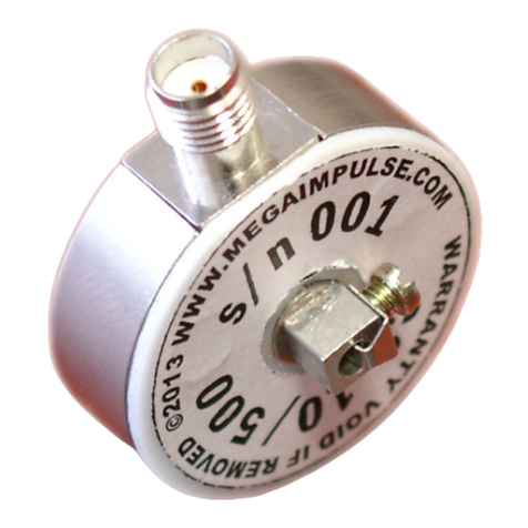
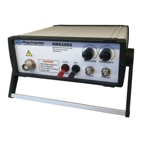
Megaimpulse RC20 User manual

RC20 RESISTIVE COUPLER
FOR NPG SERIES NANOSECOND
PULSE GENERATORS
USER MANUAL
© 2023 Megaimpulse Ltd.
V2.0 of February 07, 2023

Copyright © 2023 MEGAIMPULSE Ltd. All Rights Reserved.
MEGAIMPULSE LTD. PROVIDES THIS MANUAL "AS IS" WITHOUT WARRANTY OF ANY KIND, EITHER
EXPRESS OR IMPLIED, INCLUDING BUT NOT LIMITED TO THE IMPLIED WARRANTIES OR CONDITIONS
OF MERCHANTABILITY OR FITNESS FOR A PARTICULAR PURPOSE. IN NO EVENT SHALL
MEGAIMPULSE LTD., ITS DIRECTORS, OFFICERS, EMPLOYEES OR AGENTS BE LIABLE FOR ANY
INDIRECT, SPECIAL, INCIDENTAL, OR CONSEQUENTIAL DAMAGES (INCLUDING DAMAGES FOR
LOSS OF PROFITS, LOSS OF BUSINESS, LOSS OF USE OR DATA, INTERRUPTION OF BUSINESS AND
THE LIKE), EVEN IF MEGAIMPULSE LTD. HAS BEEN ADVISED OF THE POSSIBILITY OF SUCH
DAMAGES ARISING FROM ANY DEFECT OR ERROR IN THIS MANUAL OR PRODUCT.
SPECIFICATIONS AND INFORMATION CONTAINED IN THIS MANUAL ARE FURNISHED FOR
INFORMATION ONLY, AND ARE SUBJECT TO CHANGE AT ANY TIME WITHOUT NOTICE, AND SHOULD
NOT BE CONSTRUED AS A COMMITMENT BY MEGAIMPULSE LTD. MEGAIMPULSE LTD. ASSUMES NO
RESPONSIBILITY OR LIABILITY FOR ANY ERRORS OR INACCURACIES THAT MAY APPEAR IN THIS
MANUAL, INCLUDING THE PRODUCTS AND SOFTWARE DESCRIBED IN IT.
Products and corporate names appearing in this manual may or may not be registered trademarks or copyrights of their
respective companies, and are used only for identification or explanation and to the owners' benefit, without intent to
infringe.
Megaimpulse Ltd. contact information
Address: 28 Polytechnicheskaya str., St. Petersburg, 194021 Russia
www: http://www.megaimpulse.com
e-mail: [email protected]i.ru
fax: +7-812-297-3145

CONTENTS
Application, general view, and package content ............................................... 2
Safety manual ................................................................................................... 3
Technical specification ..................................................................................... 4
The drawing of RC20 resistive coupler ............................................................ 5
Assembling and putting into operation ............................................................. 6
Theory of the operation .................................................................................... 8
Energy loss in a cable. Calculation of the energy balance ................................ 14
Evaluation of the pulse voltage on the load and the pulse current .................... 16
Warranty ........................................................................................................... 20
RC20 User Manual 1

RC20 resistive coupler allows the precise measurement of high voltage
nanosecond pulses, including applied to (incident) and reflected from the load,
calculation of their energies and total energy balance of the discharge, as well as
estimation of the pulse voltage on the load and pulse current. Therefore,
comprehensive information about the discharge can be obtained.
Fig. 1. RC20 resistive coupler with two attached HV coaxial cables of
5 meters in length each.
PACKAGE CONTENT
Please check the package for the following items:
-RC20 resistive coupler with two attached HV coaxial cables of 5 meters in
length each;
-6 dB attenuator with N-type connectors;
-20 dB attenuator with N-type connectors;
-3 meters in length semirigid coaxial cable assembly with N-type and SMA
connectors;
-20 dB attenuator with SMA connectors;
-SMA-to-BNC adapter.
MEGAIMPULSE LTD. 2

SAFETY MANUAL
Electrical safety
RC20 resistive coupler is designed for the precise measurement of
nanosecond high-voltage pulses. Please be very careful while working with
high-voltage equipment, and operate by qualified personnel only.
Improper use may result in electric shock, strong electromagnetic
interference, or damage to other electronic equipment.
The signal from the coupler should be registered by an oscilloscope. Please
ground the oscilloscope obligatory, and divide the signal from the coupler
down to a safe level by 46 dB attenuators.
It is strongly prohibited to connect or disconnect the coupler to or from the
system while the HV pulse generator is turned on, as well as leave the N-type
connector of the coupler open, i.e. without attached attenuators. Inevitable
arcing across the open N-type connector may damage it.
Operation safety
Please read this manual before installing and using the coupler.
Make sure that all the cables are applicable and undamaged. All the
connectors should be clean, dry, and free from dust and dirt.
The coupler should operate in normal laboratory conditions. Please, avoid
dust, humidity, and temperature extremes.
Please, if you encounter any technical problems with the coupler, then
contact Megaimpulse Ltd. Do not try to repair it by yourself.
RC20 User Manual 3

TECHNICAL SPECIFICATION
Maximum HV pulse amplitude 20 kV
Maximum average power in HV cable 120 W
Pulse polarity Any
Rise time (transient response) 1.5 ns
Nominal pulse voltage attenuation of
RC20 coupler
RC20 with 46 dB attenuators
1:50 (34 dB) *)
1:10000 (80 dB)
Impedance and length of HV cables 75 Ohm, 5 m + 5 m
Output connector to the oscilloscope N-type, 50 Ohm impedance
The delay between the incident and reflected
pulses
approx. 50 ns, depending on
the coax cable length as well
as the length of the wires to
the load and load dimensions
Pulse amplitude attenuation coefficient:
per 1 meter of HV coaxial cable
per 5 meters of HV coaxial cable
k1 = 1:1.0061
k5= 1:1.031
Energy loss in dB and attenuation coefficient:
per 1 meter of HV coaxial cable
per 5 meters of HV coaxial cable
per 10 meters of HV coaxial cable
0.053 dB / k12= 1:1.0123
0.265 dB / k52= 1:1.063
0.53 dB / k102= 1:1.13
Size (for reference only) 107 х 96 х 46 mm3
*) the exact measured attenuation values are written on the coupler front label and in
the testing protocol.
To prevent damage to the coupler do not exceed the maximum pulse amplitude
and average power in HV coaxial cable.
MEGAIMPULSE LTD. 4

* All the dimensions are in mm and are given for the reference only
Fig. 2. The drawing of RC20 resistive coupler.
1 - HV coaxial cable to the NPG generator. The length is 5 meters; cable impedance
is 75 Ohm. Standard 75 Ohm coaxial connector is installed on the generator's
side.
2 - HV coaxial cable to the load. The length is 5 meters; cable impedance is 75 Ohm.
3 - N-type connector to the oscilloscope. Impedance of the output is 50 Ohm.
RC20 User Manual 5
RC20 User Manual 5

ASSEMBLING AND PUTTING INTO OPERATION
Please follow the next steps. It will help to prevent damage to the equipment
and personnel injury.
Step 1.
Unpack the package and check the presence of the following items:
-RC20 resistive coupler with two attached 5 m HV coaxial cables;
-6 dB attenuator with N-type connectors;
-20 dB attenuator with N-type connectors;
-3 m semirigid coaxial cable assembly with N-type and SMA connectors;
-20 dB attenuator with SMA connectors;
-SMA-to-BNC adapter.
Step 2.
Assemble the attenuators, measurement cable, and adapter in the following order:
-6 dB N-type attenuator;
-20 dB N-type attenuator;
-3 m semirigid coaxial cable assembly with N-type and SMA connectors;
-20 dB SMA attenuator;
-SMA-to-BNC adapter.
Attach them to the output N-type connector of the coupler as is shown in Fig.4. It
is important to keep this order for the best signal-to-noise ratio and to prevent
damage to the coupler in case of a lost connection in the cable assembly.
To prevent contacts damage, please hold the attenuator body fixed and
rotate the nut only when you attach the attenuator to the coupler.
It is strictly forbidden to apply HV pulses without the attenuators attached.
Fig.3. a) when you attach the attenuators please hold the body fixed and rotate the
nut only;
b) it is strictly forbidden to apply HV pulses without the attenuators
attached.
a)
b)
MEGAIMPULSE LTD. 6

Fig.4. RC20 resistive coupler assembling and connection.
Step 3.
Connect the HV cables to the NPG-series pulse generator and to the load as well
as connect RC20 to the oscilloscope.
Set the input impedance of the oscilloscope to 50 Ohm.
Set the external attenuation to 1:10000 or, which is more correct, to the exact
attenuation value specified in the testing protocol. Alternatively, it is possible to
calculate the pulse amplitude manually by setting the external attenuation 1:1. It is
recommended to set the vertical scale to 5 kV/div in the first case or to 500 mV per
division in the second.
Set the horizontal scale to 10 ns per division.
Step 4.
Turn on the generator and register the incident and reflected pulse waveforms by
the oscilloscope.
RC20 User Manual 7

THEORY OF THE OPERATION
RC20 resistive coupler allows the precise measurement of the output pulse
waveform of NPG-series HV pulse generators (incident pulse for the load), as well
as the pulse waveform reflected from the load. To prevent distortion, the nanosecond
pulses, similar to high-frequency signals, should be transmitted from a generator to
load through high-frequency transmission lines, for example, coaxial cables. Most
of NPG generators have 75 Ohm impedance output coaxial connector and operate
with HV coaxial cables having 75 Ohm impedance as well. According to basic
principles of HF transmission lines, the pulse energy can be absorbed by the load
completely in the case of ideal impedance matching only, i.e. if the load impedance
is fixed and equal to the cable impedance. Unfortunately, this is impossible in the
discharge applications. The impedance of the discharge gap changes from a high
before the breakdown down to typically less than one Ohm after it. Part of the pulse
energy inevitably reflects from the load and travels back to the generator. RC20
coupler is a measurement tool of the incident and reflected pulse waveforms, which
allows us to calculate the energy of both pulses, and therefore, determine the energy
balance or energy efficiency of the discharge. In addition, the evaluation of the pulse
voltage on the load and pulse current is possible.
Let us consider the basic relationships between the incident and reflected pulses
as well as RC20 operation principles in more detail. The reflection coefficient
which is defined as a ratio of the reflected
VR
and incident
VI
signals is equal to:
=
[1]
, where
ZLOAD
is the impedance of the load;
ZCABLE
is the impedance of the cable.
According to equation [1], if the load impedance
ZLOAD
is higher than
ZCABLE
, then
is within 0…1 and the reflected pulse has the same polarity. If the load impedance
is lower than
ZCABLE
, then is within -1…0 and the reflected pulse has opposite
polarity. = 1 and = -1 in two extreme cases of open or short load, and the reflected
pulse amplitude is equal to the incident one.
The pulse voltage on the load
VLOAD
and pulse current
ILOAD
are equal to:
= + [2]
== () / [3]
If the load impedance
ZLOAD
is higher than
ZCABLE
, then the reflected pulse has the
same polarity, pulse voltage amplitude on the load is equal to the sum of the incident
and reflected pulses, i.e. higher than the incident one, and the pulse current through
the load is the incident pulse current minus the reflected one, i.e. lower than the
incident pulse current (see Fig.5).
MEGAIMPULSE LTD. 8

Fig.5. Pulse voltage on the load and pulse current in the case of high impedance
load. The incident pulse is marked by red, reflected one by blue; the
propagation directions of both pulses are pointed by the arrows.
If the load impedance
ZLOAD
is lower than
ZCABLE
, then the reflected pulse has
reversed polarity. Equations [2] and [3] are also applicable. The pulse voltage on the
load is lower than the incident one, but the pulse current through the load is higher
(see Fig.6).
Fig.6. Pulse voltage on the load and pulse current in the case of low impedance
load. The incident pulse is marked by red, reflected one by blue; the
propagation directions of both pulses are pointed by the arrows.
The pulse energy can be calculated from its waveform measured in the cable by
the following equation:
=()
[4]
, where
V(t) is the captured waveform of the incident VI(t) or reflected VR(t) pulse;
ZCABLE = 75 Ohm is the cable impedance.
The absorbed by the load energy ELOAD can be easily calculated from the energies
of the incident EIand reflected ERpulses:
= [5]
RC20 User Manual 9

Of course, the energy loss ELOSS in cables should be taken into account for the
precise calculation of ELOAD. This question will be discussed in the next chapter in
more detail. RC20 operation in case of low and high impedance loads are
schematically shown in Fig.7 and Fig.8.
Fig. 7. The incident (red) and reflected (blue) pulses for short or low-impedance
load. The reflected pulse has reversed polarity. The propagation directions
of the incident and reflected pulses are pointed by the arrows.
The operation in the case of short or low-impedance load is shown in Fig.7. The
reversed polarity of the reflected pulse clearly indicates the load impedance is lower
than the cable impedance ZCABLE = 75 Ohm. The registered by oscilloscope delay
between the incident and reflected pulses is equal to the propagation time from the
coupler to the load and back. The specific propagation time along HV coaxial cable
is about 5 ns per meter, which gives ca. 50 ns of delay in cable in both directions
plus the propagation delay in cable-to-load wires and the load itself. The exact delay
should be measured in each particular application.
The high-impedance load operation is shown in Fig.8. The reflected pulse polarity
is unchanged. The delay between pulses is the same, i.e. ca. 50 ns.
The operation with the discharge load is schematically shown in Fig.9. Before the
breakdown the impedance of the discharge gap is high and the reflected pulse has
the same polarity. After the breakdown the impedance drops dramatically, and the
polarity changes. Similarly, the waveforms allow to calculate the incident and
reflected pulse energies (eq. [4]), calculate the energy which goes into the discharge
(eq. [5]), as well as estimate the pulse voltage on the load and pulse current (eq. [2]
and [3]).
MEGAIMPULSE LTD. 10

Fig. 8. The incident (red) and reflected (blue) pulses for high-impedance load or
open cable. The reflected pulse has the same polarity. The propagation
directions of the incident and reflected pulses are pointed by the arrows.
Fig. 9. The incident (red) and reflected (blue) pulses for the discharge load. The
reflected pulse changes the polarity from positive to negative, which
indicates high impedance of the load before the breakdown and low after it.
The propagation directions of the incident and reflected pulses are pointed
by the arrows.
RC20 User Manual 11

As an example, the oscillograms of the incident and reflected waveforms for the
first and the second pulses in a burst registered by RC20 coupler in case of 1 mm
gap discharge at ambient pressure are shown in Fig.10 and Fig.11. The pulse-to-
pulse interval within a burst is 10 µs (100 kHz repetition rate). One can see for the
second pulse; the discharge occurs when the amplitude is much lower because of
the presence in the gap of the excited products from the previous discharge.
It is recommended to use the oscilloscope with 1 GHz bandwidth and
10 GS/s or more.
Fig. 10. The incident and reflected waveforms of the first pulse in a burst for
1 mm gap discharge. The reflected pulse changes the polarity after the
gap breakdown. The discharge point is marked by arrow.
The scales are 5 kV/div and 10 ns/div.
Incident pulse
Reflected pulse
Discharge
point
MEGAIMPULSE LTD. 12

Fig. 11. The incident and reflected waveforms of the second pulse in a burst for
1 mm gap discharge. The discharge occurs at much lower voltage.
The scales are 5 kV/div and 10 ns/div.
Discharge
point
RC20 User Manual 9RC20 User Manual 13

ENERGY LOSS IN A CABLE
CALCULATION OF THE ENERGY BALANCE
Unfortunately, significant energy loss occurs in HV cable during the pulse
transfer, and this loss should be considered when you calculate the energy balance.
The measured energy loss (for the NPG pulse) on one meter of new HV cable is
equal to 0.053 dB which corresponds to attenuation coefficient k12= 1:1.0123. It
means the pulse energy decreases by 1.0123 times while the pulse travels along one
meter of HV cable. The cable length between RC20 coupler and the load is 5 meters.
Therefore, the energy loss on 5 meters of travel is 0.265 dB, or the attenuation
coefficient is k52= 1:1.063. The same attenuation occurs while the pulse travels back
from the load to the coupler, and the total attenuation is k102= k52× k52= 1:1.13.
Generally speaking, the energy loss depends on the frequency. The curve presented
in Fig.12 is taken from the HV cable datasheet. According to the information from
the manufacturer, the energy loss may increase up to two times due to cable aging,
i.e. degradation of the insulator and oxidation of the cable braid.
Therefore, it is reasonable to check the cable loss at least once per year. Please
increase the gap up to the discharge is eliminated completely. The incident and
reflected pulse waveforms should be similar to Fig.13. The incident pulse energy
divided by the reflected energy gives k102coefficient.
Fig.12. The energy loss per one meter of HV coaxial cable depending on the
frequency.
MEGAIMPULSE LTD. 14

Let us estimate the energy balance based on the captured incident and reflected
pulse waveforms shown in Fig. 10.
Calculated from the waveform the incident pulse energy is 24.026 mJ (eq.[4],
integral from 0 ns to 50 ns of the oscillogram). The pulse energy is attenuated by
1.063 times while it travels from the coupler to the load. Therefore, the energy of
the pulse applied to the load is 24.026/1.063≈22.60 mJ.
The reflected pulse energy is 16.163 mJ (eq.[4], integral from 50 ns to 100 ns).
And again, it is attenuated by 1.063 times while the pulse travels from the load to
RC20 coupler. Therefore, we should multiply the registered energy of the reflected
pulse by 1.063 to get the real reflected pulse energy 16.163*1.063≈17.18 mJ.
Total energy balance:
Energy of the incident pulse applied to the load 22.60 mJ
Energy of the reflected pulse from the load 17.18 mJ
Energy that goes into the discharge 22.60 - 17.18 = 5.42 mJ
One can see that only 24% of the pulse energy goes into the discharge, and
most of the pulse energy reflects back.
The energy balance calculation for the second pulse in a burst (Fig.11) gives
the following results:
Energy of the incident pulse applied to the load 20.99 mJ
Energy of the reflected pulse from the load 19.01 mJ
Energy that goes into the discharge 20.99 - 19.01 = 1.98 mJ
9.4% only of the second pulse energy goes into the discharge. The quite low
efficiency is explained by the very low impedance of the gap.
RC20 User Manual 15

EVALUATION OF THE PULSE VOLTAGE ON THE LOAD
AND THE PULSE CURRENT
RC20 can help to evaluate the pulse voltage on the load and the pulse current. At
first, the exact delay between the incident and reflected pulses should be measured.
It depends on the cable length as well as on the length of the connecting wires and
discharge electrodes. Please increase the gap between electrodes so the discharge is
eliminated completely. The pulse energy is reflected back from the load in this case,
and the reflected pulse waveform should be similar to the incident one. The typical
oscillogram of the incident and reflected pulses is shown in Fig.13, where the pulse-
to-pulse delay is measured by the interval between two peaks.
Fig.13. Measurement of the delay between incident and reflected pulses. The scales
are 5 kV/div and 10 ns/div.
Let us evaluate the pulse voltage on the load and pulse current for the oscillogram
in Fig.10. According to eq.[2] and eq.[3], and taking into account the pulse-to-pulse
delay, the voltage on the load and the current are equal to:
=()+( )[6]
= (() ( ))/ [7]
MEGAIMPULSE LTD. 16
The delay between incident and reflected pulses

Fig.14. Calculation of the pulse voltage on the discharge and pulse current:
blue solid line – calculated pulse voltage on the discharge,
red solid line – calculated pulse current through the discharge,
blue dash line – incident pulse
VI(t)
divided by 1.031 (k5),
blue dash-dot line – reflected pulse
VR(t-delay)
multiplied by 1.031 (k5).
Special attention should be taken to the stray parameters of the load. The
equivalent electrical circuit of the discharge reactor is shown in Fig.15, where
LSTRAY
is the stray inductance of the wires between the coaxial cable and the electrodes as
well as the electrodes itself,
CSTRAY
is the stray capacitance of the discharge gap, and
RPLASMA
is non-linear resistance of the plasma.
Fig.15. The equivalent electrical circuit of the discharge reactor.
CSTRAY
can be made as low as 1 pF and below, which results in its minor influence.
Indeed, the current through
CSTRAY
is equal to:
RC20 User Manual 17

=
[8]
The typical voltage rise rate of NPG generators is 5 kV/ns, which gives the
estimation of the pulse current through
CSTRAY
about 5 amperes while the total current
through the discharge is equal to a few hundred amperes.
Usually, the influence of
LSTRAY
is much higher. Exactly the stray inductance
is
responsible for the negative half-wave of the calculated voltage pulse on the load in
Fig.14 at t = 6 ns and after.
RC20 allows us to measure
LSTRAY
precisely, which may be useful for the discharge
simulation. In addition, changing the stray parameters can help to adjust the pulse
waveform on the load. Please short-circuit the discharge gap. The load becomes just
inductive, and the oscillogram should be similar to the typical one shown in Fig. 16.
Fig. 16. The oscillogram of the incident and reflected pulses when the discharge
gap is shorted. The scales are 5 kV/div and 10 ns/div.
The voltage on the inductance, is equal to:
=
[9]
MEGAIMPULSE LTD. 18
Table of contents
Other Megaimpulse Measuring Instrument manuals
Popular Measuring Instrument manuals by other brands

Aktakom
Aktakom ATE-3012 user manual

Metrohm
Metrohm Titrando 890 manual

Global Specialties
Global Specialties LCR-58 user manual

PASCO
PASCO OS-8525A instruction sheet

Precision Digital Corporation
Precision Digital Corporation PD6800-0L1 instruction manual

Eaton
Eaton Eclipse Series Installation and operation manual