manuals.online logo
Brands
  1. Home
  2. •
  3. Brands
  4. •
  5. Growatt
  6. •
  7. Measuring Instrument
  8. •
  9. Growatt TPM-CT-C-EU User manual

Growatt TPM-CT-C-EU User manual

2.
3.
4.
5.
TPM-CT-C-EU (DTSU666) Three-phase
Smart Meter Quick Guide
TPM-CT-C-EU(DTSU666) Three-phase
Smart Meter Quick Guide
1.
Overview
1.5(6)A
0.015A
0.5% of range maximum
A B C D
Item
Number
Description
A
1
Three phase meter
B
1
User Manual
C
1
RS485 cable (standard length 15m)
D
3
Current Transformer
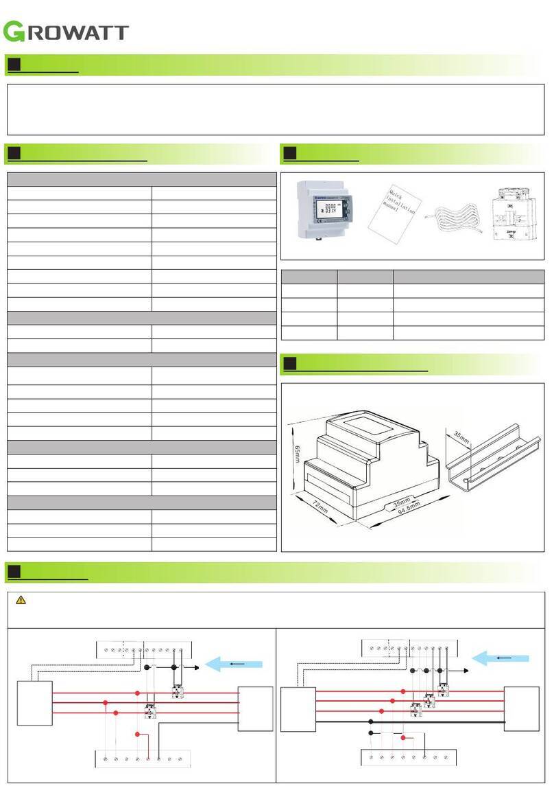
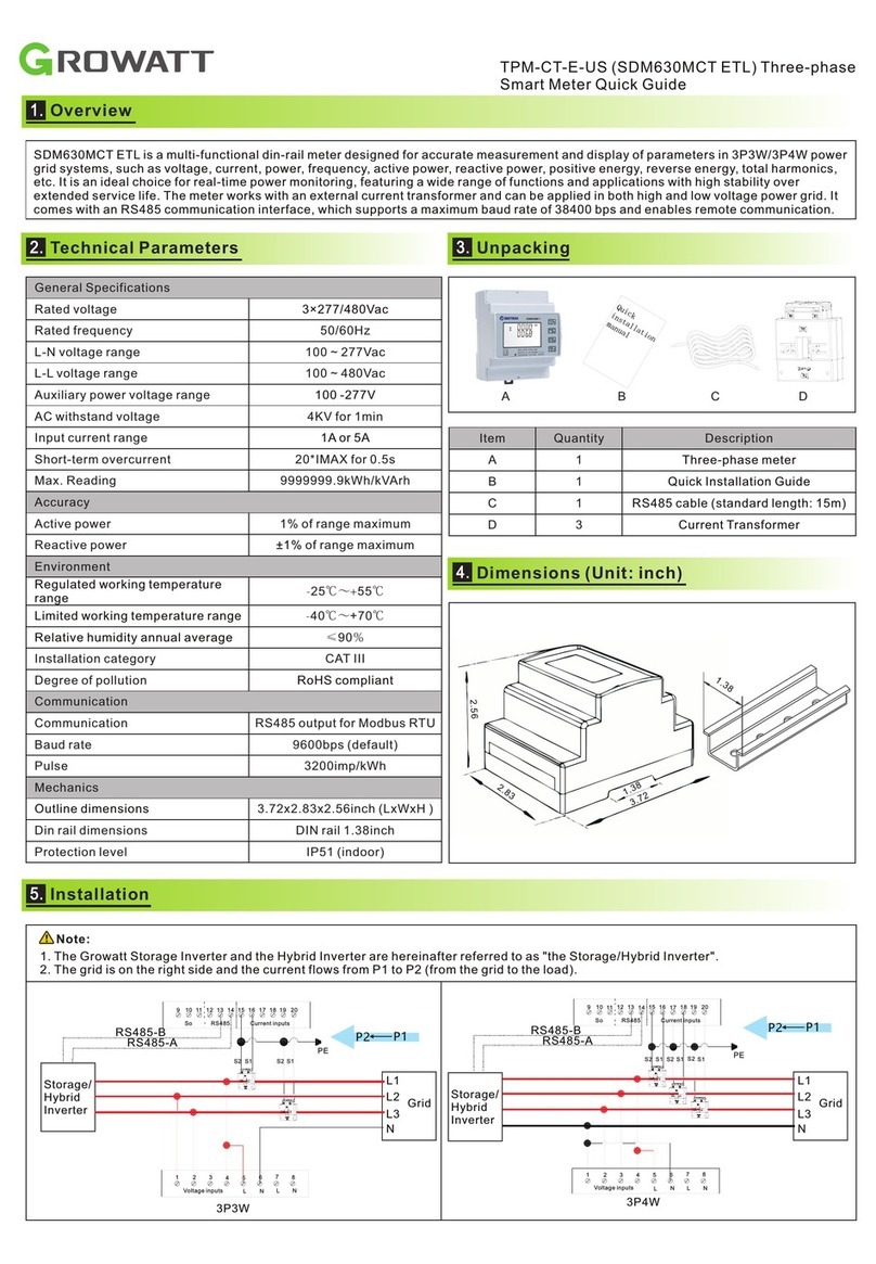
D. Connecting the meter to the Storage/Hybrid Inverter
1. The Growatt Storage Inverter and the Hybrid Inverter are hereinafter collectively referred to as “the Storage/Hybrid Inverter”.
2. The grid is on the right side and the current flows from P1 to P2 (from the grid to the load).
Note:
A. Voltage sampling and power supply wiring
Wiring of the L1 voltage sampling line: corresponding to meter Pin 2;
Wiring of the L2 voltage sampling line: corresponding to meter Pin 5;
Wiring of the L3 voltage sampling line: corresponding to meter Pin 8;
Wiring of the N voltage sampling line: corresponding to meter Pin 10.
B. Current transformer wiring
Please refer to the diagram above. The grid is on the right and the
current flows from P1 to P2 (from the grid to the load).
Wiring of the L1 CT: S1 Line corresponding to meter Pin 1, S2 Line
corresponding to meter Pin 3;
Wiring of the L2 CT: S1 Line corresponding to meter Pin 4, S2 Line
corresponding to meter Pin 6;
Wiring of the L3 CT: S1 Line corresponding to meter Pin 7, S2 Line
corresponding to meter Pin 9.
C. RS485 cable wiring
Connect the RS485A to Pin 14 and RS485B to Pin 13 (The network
cables delivered with the inverter are labeled as 485-A and 485-B; if
you are using the cables purchased yourself, make sure to
differentiate between 485-A and 485-B.)
E. When connecting the smart meter to WIT, connect one end of
the cable to Terminal 13 (485B) and Terminal 14 (485A) of the
smart meter and the other end to Pin 6 (485A) and Pin 7 (485B) of
the COM1 port.
Note: In most cases, the red cable is used for 485A and the black
cable for 485B.
Red(484A)---COM1(6)
Black(484B)---COM1(7)
COM1
F. Dismantle the 16-pin connector delivered with WIT and set
aside the water-proof plug. Route the cables through each part
sequentially, then connect them to Pin 6 and Pin 7. Finally,
connect the connector to the COM1 port of the inverter.
G. The standard RS485 cable length is 15m. If a longer RS485
cable is required, please use an intact cable and make sure the
RS485 cable is less than 100m (the recommended length is less
than 25m).
36910
14710
1314161719212425
2325358381112
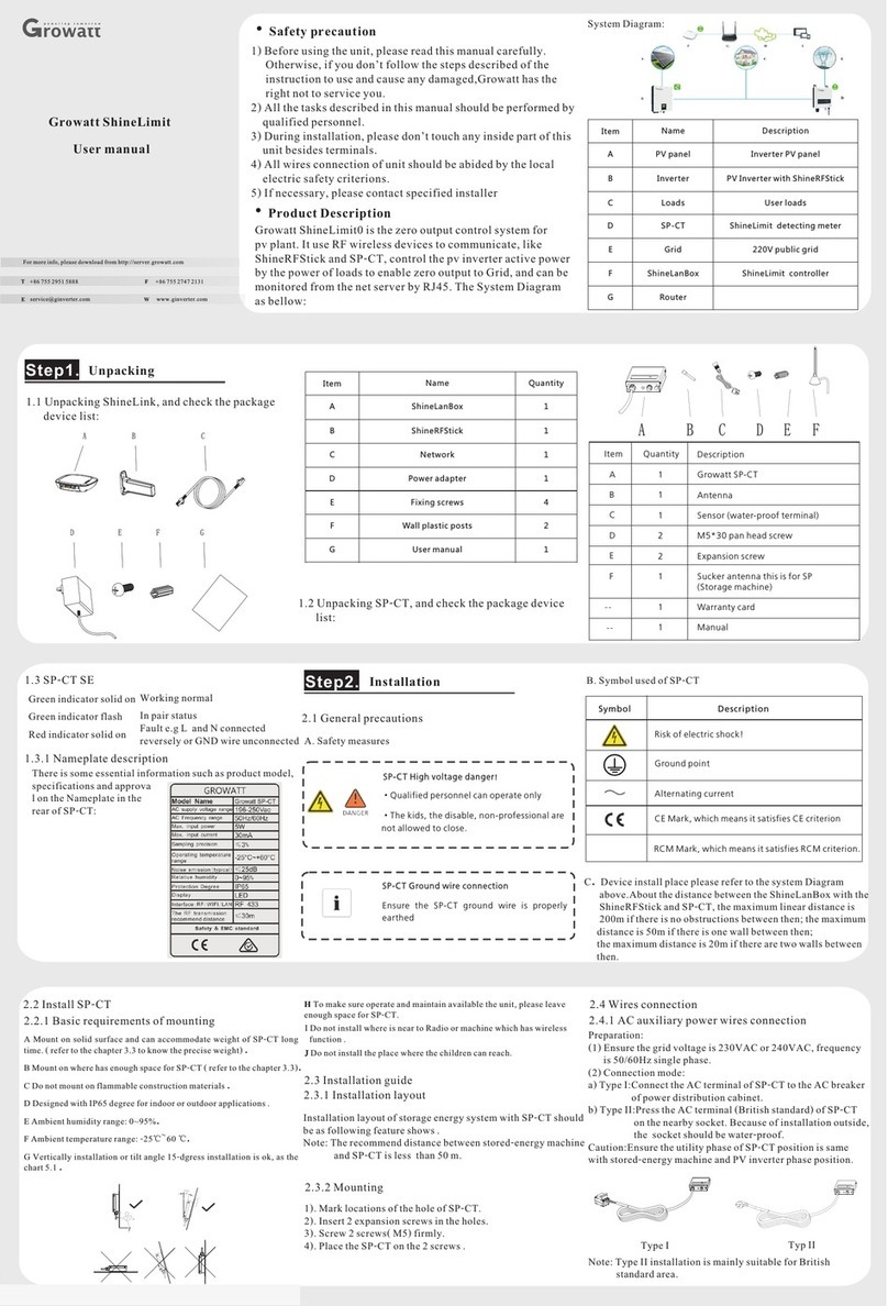
The system wiring diagram is shown as follows. In case that the meter is not
operating properly, you can refer to it to check the wiring. For the Growatt
Storage/Hybrid Inverter, please connect the meter to the COM1 port.
1. Connect the L/N input and output cables correctly.
Please ensure that the input voltage and input current
are within the permissible range; otherwise the meter
will be damaged.
2. The input and output wires of the meter should be
correctly connected; otherwise, the meter will not be
able to operate properly.
Note:
Storage/Hybrid Inve rter
COM1
6
7
GRID
LOAD
Grid-T
Secondary load
Primary load
AC
Breaker
Load
Break er
Main
Breaker
EART H
S1
S1
S1
S2
S2
S2
Power cable
sample cable
communication ca ble
P1:Grid
side
P2:PCS
side
369 10
14710
13 14 16 17 19 21 24 25
232 535 838 11 12
Grid-N
Grid-S
Grid-R
Load -T
Load -R
Load -S
Load -N
Grid -PE
Load -PE
Grid
L1
L2
L3
N
RS485-A
RS485-B
369 10
232 535 838 11 1 2
14710
13 14 16 1 7 19 2 1 24 2 5
S1
S2
S1
S1
S2
S2
PE
P2←P1
Storage
/Hybrid
Inverter
DTSU666 series three phase four wire electronic energy meter (din-rail) is designed based on power monitoring and energy metering
demands for electric power system, communication industry, construction industry, etc. as a new generation of intelligent instrument
combining measurement and communication function, mainly applied into the measurement and display for the electric parameters in the
electric circuit including three voltage, three current, active power, reactive power, frequency, positive&negative energy, four-quadrant
energy, etc. Adopting the standard DIN35mm din rail mounting and modular design, it is characterized with small volume, easy installation
and easy networking. It is compatible with Growatt Three-phase Storage/Hybrid Inverters.
36910
14710
1314161719212425
2325358381112
COM1(6、7)
Download
Manual
Growatt New Energy
Shenzhen Growatt New Energy CO.,LTD
4-13/F, Building A, Sino-German (Europe) Industrial Park,
Hangcheng Ave, Bao'an District, Shenzhen, China
+86 755 2747 1942
www.ginverter.com
T
E service@ginverter.com
W
GR-UM-341-A-00
7.
8.
Service and contact
Note: The communication address of the meter and the Growatt Three-phase Storage/Hybrid inverter is 04 by default, the baud rate is 9600.
If the meter fails to communicate with the inverter, you can check the parameter settings by following the instructions:
Button description: “SET” button represents“confirmation”,or“cursor shift”(when entering digits),“ESC” button represents “exit”, “→”( )
button represents“add”. The password is 701 by default.
Diagram 2 Setting examples for modifying current ratio
Diagram 3 Setting examples for modifying communication address and baud rate
Troubleshooting
Fault phenomenon
Reason analysis
Solution
Metering inaccuracy
1. Wiring error, check whether the corresponding
phase sequence of voltage and current is correct.
2. Check if the output line of the current transformer
is reversely connected.
3. The transformer ratio is not set, and the meter
displays the secondary data.
1. Refer to the wiring diagram to check the wiring.
2. If the transformer ratio setting is wrong, please
set the voltage ratio and current ratio correctly.
3. If the issue still exists, please contact your local
supplier.
RS485 communication error
(Inverter error 401)
1. The RS485 communication cable is
disconnected, short circuit or reversely connected.
2. The address, baud rate, data bit and parity bit of
the meter are not in accordance with the inverter .
1. If there is a problem with the communication
cable, please replace the communication cable.
2. Set the address, baud rate, data bit and parity bit
of the meter through buttons.
3. If the issue still exists, please contact your local
supplier.
NO
Display interface
Instruction
NO
Display interface
Instruction
1
Imported active energy
=10000.00KWh
10
Phase C current =5.002A
2
Exported active energy
=2345.67KWh
11
Combined phase active power
=3.291KW
3
Communication protocol is
ModBus-RTU. N1 indicates
none parity, 1 stop bit.
9600 indicates that the baud
rate is 9600bps.
004 indicates that the meter
default address is 04.
12
Phase A active power
=1.090KW
4
13
Phase B active power
=1.101KW
5
Phase A voltage =220.0V
14
Phase C active power
=1.100KW
6
Phase B voltage =220.1V
15
Combined phase power factor
PFt=0.500L
7
Phase C voltage =220.2V
16
Phase A power factor
Pfa=1.000L
8
Phase A current =5.000A
17
Phase B power factor
Pfb=0.500L
9
Phase B current =5.001A
18
Phase C power factor Pfc =-
0.500L
6.
The displayed interfacial electrical parameter and power data
are both primary-side data (which is calculated basen on the
value of the current and the voltage). The energy measurement
value is displayed in seven bits, with the display range from
0.00kWh to 999999.9 kWh.

This manual suits for next models

1

Other Growatt Measuring Instrument manuals

Growatt Smart Meter-US User manual

Growatt

Growatt Smart Meter-US User manual

Growatt TPM-CT-E-EU User manual

Growatt

Growatt TPM-CT-E-EU User manual

Growatt Lucas User manual

Growatt

Growatt Lucas User manual

Growatt Shine3G Instruction sheet

Growatt

Growatt Shine3G Instruction sheet

Growatt MIN TL-X Manual

Growatt

Growatt MIN TL-X Manual

Growatt ShineLink-X User manual

Growatt

Growatt ShineLink-X User manual

Growatt MOD 3-15KTL3-X User manual

Growatt

Growatt MOD 3-15KTL3-X User manual

Growatt ShineMaster User manual

Growatt

Growatt ShineMaster User manual

Growatt TPM-E SDM630-Modbus V3 User manual

Growatt

Growatt TPM-E SDM630-Modbus V3 User manual

Growatt ShineWiFi-X User manual

Growatt

Growatt ShineWiFi-X User manual

Growatt ShineWiFi-S Instruction sheet

Growatt

Growatt ShineWiFi-S Instruction sheet

Growatt TPM-CT-E-US User manual

Growatt

Growatt TPM-CT-E-US User manual

Growatt ShineWiFi Instruction sheet

Growatt

Growatt ShineWiFi Instruction sheet

Growatt ShineLink-X Operating and maintenance instructions

Growatt

Growatt ShineLink-X Operating and maintenance instructions

Growatt ShineWiFi-X User manual

Growatt

Growatt ShineWiFi-X User manual

Growatt SPH Series User manual

Growatt

Growatt SPH Series User manual

Growatt ShineWiFi-X Instruction sheet

Growatt

Growatt ShineWiFi-X Instruction sheet

Growatt ShineVision User manual

Growatt

Growatt ShineVision User manual

Growatt ShineWiFi-X User manual

Growatt

Growatt ShineWiFi-X User manual

Growatt Shine GPRS-F User manual

Growatt

Growatt Shine GPRS-F User manual

Growatt ShineLimit User manual

Growatt

Growatt ShineLimit User manual

Popular Measuring Instrument manuals by other brands

Herutu 21UD instruction manual

Herutu

Herutu 21UD instruction manual

Casella HB4056-01 dBadge2 Field guide

Casella

Casella HB4056-01 dBadge2 Field guide

Orbitalum ORBmax operating instructions

Orbitalum

Orbitalum ORBmax operating instructions

Omega FTB700 user guide

Omega

Omega FTB700 user guide

Magnescale SR75 Supplement

Magnescale

Magnescale SR75 Supplement

National Instruments NI PXIe-5105 Getting started guide

National Instruments

National Instruments NI PXIe-5105 Getting started guide

Endress+Hauser Liquicap M FMI52 Brief operating instructions

Endress+Hauser

Endress+Hauser Liquicap M FMI52 Brief operating instructions

C-LOGIC 8900 user manual

C-LOGIC

C-LOGIC 8900 user manual

PR electronics 5714 user manual

PR electronics

PR electronics 5714 user manual

ATAGO PAL-24S instruction manual

ATAGO

ATAGO PAL-24S instruction manual

Emerson Micro Motion LNG Series Configuration and Use Manual

Emerson

Emerson Micro Motion LNG Series Configuration and Use Manual

Agilent Technologies 3200D operating guide

Agilent Technologies

Agilent Technologies 3200D operating guide

PCE Instruments PCE-428 user manual

PCE Instruments

PCE Instruments PCE-428 user manual

Nordson Sealant Equipment PRO-METER V2K Customer product manual

Nordson Sealant Equipment

Nordson Sealant Equipment PRO-METER V2K Customer product manual

Altana BYK byko-visc RT Lite Short instructions

Altana

Altana BYK byko-visc RT Lite Short instructions

AMTAST RHS-4ATC operation instruction

AMTAST

AMTAST RHS-4ATC operation instruction

Honeywell Q340A installation instructions

Honeywell

Honeywell Q340A installation instructions

PRÜFTECHNIK VIBXPERT II Short instructions

PRÜFTECHNIK

PRÜFTECHNIK VIBXPERT II Short instructions

manuals.online logo
manuals.online logoBrands
  • About & Mission
  • Contact us
  • Privacy Policy
  • Terms and Conditions

Copyright 2025 Manuals.Online. All Rights Reserved.