Megamoto MM-B212 MXS User manual

MM-B212 MXS
(MEGA MAX SUSPENSION)
ASSEMBLY INSTRUCTIONS
READ ALL OF THE INSTRUCTIONS BEFORE REMOVING
BIKE FROM THE STEEL SHIPPING CRATE AND
ASSEMBLING THE BIKE. MAKE SURE YOU UNDERSTAND
THE INSTRUCTIONS BEFORE YOU BEGIN.

MM-B212 MXS ASSEMBLY INSTRUCTIONS
WEAR PROTECTIVE GLOVES WHEN HANDLING THE STEEL CRATE
UNPACKING
A
B
C
A. After removing the outer carboard
box, remove the Parts Box between
the 2 front forks. Open the parts box.
Locate the axle bolt, 2 spacers, and
nut that secure the 2 front forks to
the top of the steel shipping crate.
Remove the nut, 2 spacers and axle
bolt and place in the Parts Box.
B. Slide each fork out of the fork
supports on the top of the steel crate.
(Picture shows upper crate removed
for clarity.)
Axle Bolt
2 Spacers
Nut
C. Place the forks on a soft surface like
a towel or moving blanket along with
the parts in the Parts Box.
Steel tubes that hold the forks
PARTS BOX

MM-B212 MXS ASSEMBLY INSTRUCTIONS
UNPACKING
WEAR PROTECTIVE GLOVES WHEN HANDLING THE STEEL CRATE
D
E
F
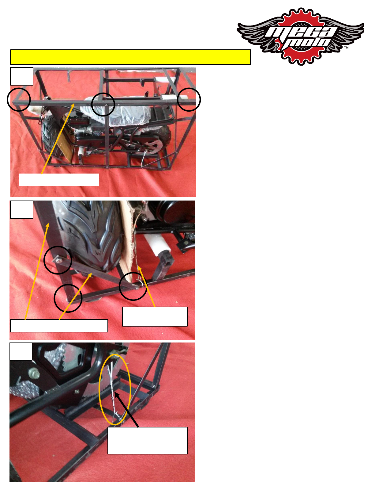
D) Remove the 6 nuts and bolts
that secure the top of the steel
shipping crate and lift off and
discard the top.
Top steel shipping crate
E) Remove the 18 nuts and bolts
that secure the vertical and angled
steel crate supports and remove
the supports and discard. Remove
the front wheel/tire assembly. Cut
and remove the 2 steel wires that
secure the front of the minibike
frame to the bottom of the steel
shipping crate.
Vertical and angled supports
Cut the 2 wires on the
front of the minibike
F) Leave the 2 rear steel wires
that secure the minibike to the
bottom of the steel shipping crate.
These will help to secure the bike
until you have completed the
assembly.
Do not cut the 2 wires at
the rear of the minibike
until assembly is complete.

MM-B212 MXS ASSEMBLY INSTRUCTIONS
UNPACKING
WEAR PROTECTIVE GLOVES WHEN HANDLING THE STEEL CRATE
G
H
I
G) Cut the zip tie that secures the
handlebar assembly at the top of the
minibike frame.
H) Cut the zip tie that secures the
handlebar at the bottom of the steel
shipping crate. Remove the bubble
wrap from the handlebar.
I) Cut the ties that secure the front
fender, located on top of the rear
wheel. Remove the bubble wrap.
Remove the front wheel. Sort the
parts and arrange them as shown in
the next 2 pages to make assembly
easier.

FRONT FORK , UPPER FORK PLATE, and FRONT NUMBER PLATE
NUMBER PLATE
1) FRONT FORK ASSEMBLY (1PC)
2) AXLE NUT (1PC)
3) AXLE SPACERS (2PCS)
4) FRONT AXLE (1PC)
5) FORK BOLTS (2PCS)
6) STEERING STEM NUT (1PC)
7) STEERING STEM FLAT
WASHER (1PC)
8) UPPER FORK PLATE
PARTS:
10
99) FRONT NUMBER PLATE (1PC)
10) FRONT NUMBER PLATE
BOLTS, (2PCS) and NUT (1PC)
MM-B212 MXS ASSEMBLY INSTRUCTIONS
1
234
56
7
8
FORKS, AXLE, UPPER FORK PLATE

FRONT FENDER
11) FRONT FENDER with MOUNTING BRACKET (1PC)
12) FRONT FENDER NUTS (2PCS)
13) FRONT FENDER BOLTS (2PCS)
PARTS:
MM-B212 MXS ASSEMBLY INSTRUCTIONS
11
12 13

FRONT FORK:
MM-B212 MXS ASSEMBLY INSTRUCTIONS
1
2
1) After removing all of the ties
and wrapping that secure the
handlebar and front fork, rest the
handlebar over the lower fork
plate. Keep the brake lever on the
left, (as seen when seated on the
bike) and the throttle and switch
on the right. Make sure not to
twist the wires, cable, and hose.
2) Place the upper fork plate over
the steering stem. The number
plate bracket should be facing
forward.
3) Place the steering stem flat
washer over the steering stem.
3
LOWER FORK
PLATE
STEERING STEM

FRONT FORK:
MM-B212 MXS ASSEMBLY INSTRUCTIONS
4) Install the steering stem nut
onto the steering stem and
hand tighten.
5) Install the chrome end of
one fork into the lower fork
plate and push it up until it
reaches the upper fork
plate. There is no specific
left or right fork, either one
can go on the left or right.
6) Line up the top of the fork
with the hole in the upper
fork plate.
7) Install the upper fork bolt
and tighten by hand.
4
5
67

FRONT FORK:
MM-B212 MXS ASSEMBLY INSTRUCTIONS
8 8) Install the fork and upper
fork bolt on the other side
and hand tighten.
9) Tighten the two upper fork
bolt securely. (34 N.m/25
ft.lb.)
9
10 10) Tighten the 2 fork
pinch bolts securely,
(12N.m/9 ft.lb)

MM-B212MX (MEGA MAX) ASSEMBLY INSTRUCTIONS
12
13
HANDLEBAR
12) Flip the handlebar back
and insert the bolts on the
bottom of the handlebar
clamps into the 2 holes in the
top fork plate.
13) Make sure the wires,
cable, and hose are located
in front of the upper fork
plate and under the top
number plate bracket as
shown.
11) Tighten the steering stem
nut securely. (54 N.m/40
ft.lb.)
11

MM-B212MX (MEGA MAX) ASSEMBLY INSTRUCTIONS
HANDLEBAR
Front of fender is
rounded
Rear of fender is
square
15) Install the front fender by
bringing the fender up to the lower
fork plate and aligning the holes in
the fender bracket and lower fork
plate. Install the 2 bolts from the
top through the lower fork plate
then the fender plate.
15
16 16) Install the nuts on the bolts
and tighten securely, (10N.m/7
Ft.lb)
Install the nut
with the wide
flat part up,
against the
fender bracket.
14 14) Install the 2 nuts on the
handlebar clamp bolts with
the large flat surface of the
nut up against the upper
fork plate and tighten
securely (26 N.m or 19 ft.
lbs)

MM-B212MX (MEGA MAX) ASSEMBLY INSTRUCTIONS
17
18
19
18) Insert the axle bolt
about 1 inch into the right
fork leg, as viewed sitting on
the bike, left as pictured.
19) Install one axle spacer
on the axle bolt.
FRONT WHEEL
17) The small tabs on the
lower part of the black fork
legs should face in. If they
don’t, rotate the black fork
legs so that the tabs face in.

MM-B212MX (MEGA MAX) ASSEMBLY INSTRUCTIONS
20
21
22
20) Next you will insert the axle
bolt into the axle bearing…
21) Then push through to the
other side of the wheel until
about 1 inch of the axle bolt
comes through.
22) Place the other axle spacer
on the axle bolt and align the
hole in the fork leg with the axle
spacer and bolt.
FRONT WHEEL
Position the
front wheel
as pictured,
the tread
pattern in
the position
of a “V” as
shown.

MM-B212MX (MEGA MAX) ASSEMBLY INSTRUCTIONS
25
23
24
23) Push the axle bolt all the
way through the spacer and the
hole in the fork leg.
24) Install the nut with the large
flat spot facing toward the wheel.
25) Tighten the nut securely (54
N.m/ 40 lb. ft)
FRONT WHEEL

MM-B212MX (MEGA MAX) ASSEMBLY INSTRUCTIONS
NUMBER PLATE
26
27
26) Locate the 2 number
plate mounting brackets on
the front of the forks at the
steering head. Place the
number plate over the
mounting brackets and align
the holes on the plate with
the threaded holes in the
brackets.
27) Insert the top screw
first and finger tighten,
then insert and tighten the
bottom screw. Tighten the
top screw.

MM-B212MX (MEGA MAX) ASSEMBLY INSTRUCTIONS
28
29
28) Cut the 2 steel ties that secure
the rear of the minibike to the
lower steel shipping crate. Tilt the
minibike slightly to the left, as
viewed sitting on the bike, or left
as pictured and turn the handlebar
clockwise all the way. The
handlebar grip should be higher
than the brake master cylinder.
PURGE AIR FROM BRAKE LINE
DURING SHIPPING SOME AIR MAY HAVE ENTERED THE BRAKE HOSE. THIS PROCEDURE WILL PURGE AIR FROM THE HOSE
AND ENSURE PROPER BRAKE PERFORMANCE.
BRAKE MASTER
CYLINDER
29) Gently pull the brake lever
toward the handle, DO NOT PULL
THE LEVER ALL THE WAY TO THE
HANDLEBAR. Pull the lever only
about ½ inch. Remove the small
black plastic wedge placed between
the lever and the master cylinder
30) Release the lever then pull it
to the handle bar again, only
about ½ inch. Repeat this process
several times. Then pull the lever
slowly toward the grip as far as it
will go. The lever should offer
resistance the more it is pulled
toward the grip and should not
be able to be pulled all the way
to the grip. Repeat 38 and 39
until the brake lever offers firm
resistance and will not pull all the
way to the grip.
30
Remove the small black plastic wedge
from the lever.

ADD OIL
31) BEFORE YOU START THE
BIKE YOU MUST ADD 20oz. OF
10W30 MOTOR OIL TO THE
ENGINE.
Add oil into the oil filler neck
on the front of the engine.
NOTE: Whenever checking the
engine oil level, the bike
should be on level ground and
held vertical on its two
wheels, not resting on the side
stand as the proper oil level
will not be indicated on the
dipstick.
32) After adding oil, place the
dipstick squarely in the filler
hole but do not screw it in. Pull
out the dipstick and see where
the oil level is on the dipstick.
Add as needed. Replace the
dipstick and tighten .
Proper Oil Level
Oil is not provided with the mini bike. 20oz of 10W30 Motor Oil is needed.
31
32
MM-B212MX (MEGA MAX) ASSEMBLY INSTRUCTIONS

MM-B212MX (MEGA MAX) ASSEMBLY INSTRUCTIONS
ALWAYS WEAR PROTECTIVE GEAR SUCH AS A HELMET,
GLOVES, BOOTS, LONG SLEEVE SHIRT, AND PANTS
WHEN RIDING.
BE SURE TO OIL THE CENTRIFUGAL CLUTCH
BEFORE AND AFTER EACH RIDE AS
INSTRUCTED IN YOUR OWNER’S MANUAL.
STARTING AND RUNNING THE BIKE
33
34
35
Assembly is complete. The
minibike can be rolled off of the
bottom steel shipping crate.
33) Add regular gasoline to the
gas tank. Non ethanol fuel mixed
with a fuel stabilizer like Sta-Bil is
best.
34) Move the grey choke lever to
the left, the “START” position,
and the black fuel lever to the
right “ON” position. Allow
time for fuel to flow into and
fill the carburetor, about 1
minute.
35) Press the smaller button on
the engine stop switch, located
on the right handlebar. This is the
ON position.

MM-B212MX (MEGA MAX) ASSEMBLY INSTRUCTIONS
38
37
36 36) Pull the pull start lever
quickly to start the engine. Pulling
it slowly will not turn the engine
fast enough to start the engine.
The pull start does not have to be
pulled all the way out to start, just
a fast and frim pull from your
extended arm until your hand is
pulled to your chest will work.
37) After the bike has had a short
time to warm up, move the choke
lever to the right “RUN” position.
Leave the fuel lever ON.
STARTING AND RUNNING THE BIKE
38) To turn off the engine, press
the large button on the engine
stop switch, this is OFF.

STARTING AND RUNNING THE BIKE
MM-B212MX (MEGA MAX) ASSEMBLY INSTRUCTIONS
39 39) When you are done riding,
move the fuel lever to the left to
the “OFF” position.
BE SURE TO OIL THE CENTRIFUGAL
CLUTCH BEFORE AND AFTER EACH RIDE
AS INSTRUCTED IN YOUR OWNER’S
MANUAL.
Other Megamoto Motorcycle manuals