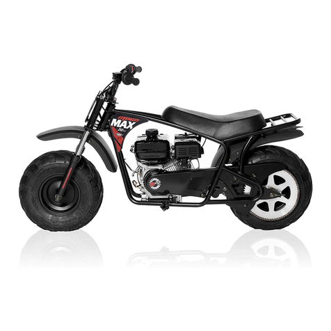
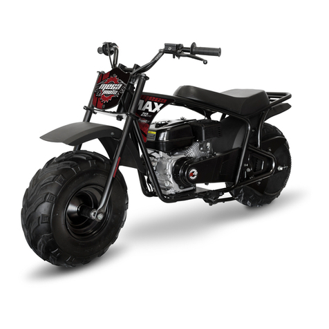
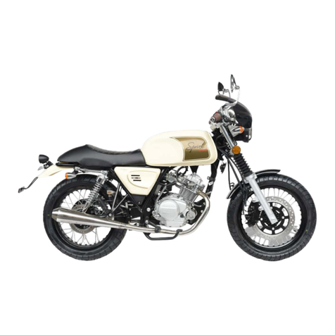
Megamoto MM-B212 PRO User manual

MM-B212 PRO
ASSEMBLY INSTRUCTIONS
READALLOFTHEINSTRUCTIONSBEFOREREMOVING
BIKEFROMTHESTEELSHIPPINGCRATEAND
ASSEMBLINGTHEBIKE.MAKESUREYOUUNDERSTAND
THEINSTRUCTIONSBEFOREYOUBEGIN.

MM-B212 PRO ASSEMBLY INSTRUCTIONS
WEARPROTECTIVEGLOVESWHENHANDLINGTHESTEELCRATE
UNPACKING
A
B
C
A. Afterremovingtheoutercarboard
box,removethePartsBoxbetween
the2frontforks.Openthepartsbox.
Locatetheaxlebolt,2spacers,and
nutthatsecurethe2frontforksto
thetopofthesteelshippingcrate.
Cuttheziptiethatsecuresthefront
brakecalipertotheaxlebolt.
Removethenut,2spacersandaxle
boltandplaceinthePartsBox.
B. Slideeachforkoutofthefork
supportsonthetopofthesteelcrate.
(Pictureshowsuppercrateremoved
forclarity.)
AxleBolt
2Spacers
Nut
C. Placetheforksonasoftsurfacelike
atowelormovingblanketalongwith
thepartsinthePartsBox.
Steeltubesthatholdtheforks
PARTSBOX

MM-B212 PRO ASSEMBLY INSTRUCTIONS
UNPACKING
WEARPROTECTIVEGLOVESWHENHANDLINGTHESTEELCRATE
D
E
F
D)Removethe6nutsandbolts
thatsecurethetopofthesteel
shippingcrateandliftoffand
discardthetop.
Topsteelshippingcrate
E)Removethe18nutsandbolts
thatsecuretheverticalandangled
steelcratesupportsandremove
thesupportsanddiscard.Remove
thefrontwheel/tireassembly.Cut
andremovethe2steelwiresthat
securethefrontoftheminibike
frametothebottomofthesteel
shippingcrate.
Verticalandangledsupports
Cutthe2wiresonthe
frontoftheminibike
F)Leavethe2rearsteelwires
thatsecuretheminibiketothe
bottomofthesteelshippingcrate.
Thesewillhelptosecurethebike
untilyouhavecompletedthe
assembly.
Donotcutthe2wiresat
therearoftheminibike
untilassemblyiscomplete.

MM-B212 PRO ASSEMBLY INSTRUCTIONS
UNPACKING
WEARPROTECTIVEGLOVESWHENHANDLINGTHESTEELCRATE
G
H
I
G)Cutthe2ziptiesand1stringthat
securethehandlebarassemblytothe
topoftheminibikeframe.Removethe
bubblewrap.
H)Movethefrontbrakecalipertothe
leftofthebikeandletithangthere.
I)Cutthetiesthatsecurethefront
fender,locatedontopoftherear
wheel.Removethebubblewrap.
Removethefrontwheel.Sortthe
partsandarrangethemasshownin
thenext2pagestomakeassembly
easier.

FRONTFORK,UPPERFORKPLATE,andFRONTNUMBERPLATE
1) FRONTFORKASSEMBLY
RIGHT(1PC)1A)FRONTFORK
ASSEMBLYLEFT(1PC)
2) AXLENUT(1PC)
3) AXLESPACERS(2PCS)
4) FRONTAXLE(1PC)
5) FORKBOLTS(2PCS)
6) STEERINGSTEMNUT(1PC)
7) STEERINGSTEMFLAT
WASHER(1PC)
8) UPPERFORKPLATE
9) FRONTWHEELASSEMBLY
PARTS:
MM-B212 PRO ASSEMBLY INSTRUCTIONS
234
56
7
8
FORKS,AXLE,UPPERFORKPLATE
1
1A

FRONTFENDER
10) FRONTFENDERwithMOUNTINGBRACKET(1PC)
11) FRONTFENDERNUTS(2PCS)
12) FRONTFENDERBOLTS(2PCS)
13) HEADLIGHTASSEMBLYWITHMOUNTING
BRACKET(1PC)
PARTS:
MM-B212 PRO ASSEMBLY INSTRUCTIONS
10
11 12
13

FRONTFORK:
MM-B212 PRO ASSEMBLY INSTRUCTIONS
1)Afterremovingalloftheties
andwrappingthatsecurethe
handlebarandfrontfork,restthe
handlebaroverthelowerfork
plate.Keepthethrottleand
switchontheright,(asseenwhen
seatedonthebike).Makesure
nottotwistthewires,cable,and
hoses.Thefrontbrakecaliper
shouldhangonthehoseonthe
leftofthebikewiththehoseover
thebackofthelowerforkplate
2)Placetheupperforkplateover
thesteeringstem.
3)Placethesteeringstemflat
washeroverthesteeringstem.
3
1
LOWERFORK
PLATE
FrontBrake
Hose
2
STEERINGSTEM

FRONTFORK:
MM-B212 PRO ASSEMBLY INSTRUCTIONS
4) Installthesteeringstemnut
ontothesteeringstemand
handtighten.
5) Installthechromeendof
theleftforkintothelower
forkplateandpushitup
untilitreachestheupper
forkplate.Theleftforkhas
thetwobrakecaliper
mountingholes.
6) Lineupthetopofthefork
withtheholeintheupper
forkplate.
7) Installtheupperforkbolt
andtightenbyhand.
4
5
67

FRONTFORK:
MM-B212 PRO ASSEMBLY INSTRUCTIONS
88)Installtheforkandupper
forkboltontheotherside
andhandtighten.
9)Tightenthetwoupperfork
boltsecurely.(34N.m/25
ft.lb.)
9
10
10)Placethefontbrake
hosewiththerubber
sleeveintothehoseclipon
theleftboltofthelower
forkplate10A)Tightenthe
2forkpinchboltssecurely,
(12N.m/9ft.lb)
10A

MM-B212 PRO ASSEMBLY INSTRUCTIONS
12
13
HANDLEBAR
12)Flipthehandlebarback
andinserttheboltsonthe
bottomofthehandlebar
clampsintothe2holesinthe
topforkplate.
13)Makesurethewires,
cable,andhosearelocated
infrontoftheupperfork
plateandthattheyarenot
twistedtogether.Makesure
thecablesandhosesare
routedasshown.
11)Tightenthesteeringstem
nutsecurely.(54N.m/40
ft.lb.)
11

MM-B212 PRO ASSEMBLY INSTRUCTIONS
HANDLEBAR
Frontoffenderis
rounded
Rearoffenderis
square
15)Installtheheadlightassembly
andfrontfenderbyplacingthe
headlightbracketontopofthelower
forkplate.Aligntheholesinthe
brackettotheforkplateandinsert
the2boltsthroughthetopofthe
bracketandthroughthelowerfork
plate.Bringthefenderbracketupto
thebottomofthelowerforkplate
andinsertthe2boltsintotheholes
inthefenderbracket.
15
16 16)Installthenutsonthebolts
andtightensecurely,(10N.m/7
Ft.lb)
Installthenut
withthewide
flatpartup,
againstthe
fenderbracket.
14 14)Installthe2nutsonthe
handlebarclampboltswiththe
largeflatsurfaceofthenutup
againsttheupperforkplateand
tightensecurely(26N.mor19
ft.lbs)
Headlight
Bracket
Fender
Bracket
LowerFork
Plate

MM-B212 PRO ASSEMBLY INSTRUCTIONS
NUMBERPLATE
17
18
17)Locatethe3pinwire
connectorfromthe
headlight,3wires,(White,
GreenBlue),andconnectit
totheother3pinconnector
with2wires,(Black,White).
Theconnectorsfitonlyone
way.
18)Makesuretheother
wireconnectorsare
connected.2pinredand
whitewiresareconnected
totheother2pinredand
whitewires.2blackwires
areconnectedtotheother
2blackwires.

MM-B212 PRO ASSEMBLY INSTRUCTIONS
19
21
20)Placethefrontwheelinbetweentheforklegs,withthetreadasshownwitha“V”pattern
andthediscontheleftside,(asseenwhensittingonthebike).20A)Inserttheaxleboltintothe
wheelbearingandthroughthewheel.Installthesecondwheelspacer.20B)Pushtheaxle
throughtherightforkleg.
21)Installthenutonthe
axleasshownandtighten
securely.(54N.m/40Ft.lb)
FRONTWHEEL
19)Inserttheaxlebolt
throughtheoutsideofthe
rightforkleg,(asseen
whensittingonthebike,
leftasshown),sothatit
sticksoutontheinsideof
thelegabout1inch.Place
theaxlespacerontheaxle
asshown.
Spacer
Tabonfork
legshould
facein
20 20A 20B

MM-B212 PRO ASSEMBLY INSTRUCTIONS
22
23
24
22)Removetheblackplastic
spacerbetweenthebrakepads
inthefrontbrakecaliper.Make
surethebrakepadshavea
spacebetweenthem.
23)Placethebrakecaliperover
thebrakedisconthefront
wheelmakingsurethediscis
placedbetweenthe2brake
pads.
24)Alignthe2threadedholesof
thebrakecaliperwiththe2holes
intheforkleg.Insertthe2bolts
andhandtighten.Tightenthe2
boltssecurely,(22N.m/16Ft.lb)
FRONTWHEEL
Spacebetweenthe
brakepads
BrakeDisc
BrakePads

MM-B212 PRO ASSEMBLY INSTRUCTIONS
25
26
25)Locatetherubbersleeveon
thebrakehose.
26)Slidetherubbersleeveupto
thehoseclipandpushtherubber
sleeveintothecliptosecurethe
brakehose.
FRONTWHEEL

MM-B212 PRO ASSEMBLY INSTRUCTIONS
27
28
27)Cutthe2steeltiesthatsecurethe
rearoftheminibiketothelowersteel
shippingcrate.Tilttheminibikeslightly
totheleft,asviewedsittingonthe
bike,orleftaspicturedandturnthe
handlebarclockwisealltheway.The
handlebargripshouldbehigherthan
thebrakemastercylinder.
PURGEAIRFROMBRAKELINE
DURINGSHIPPINGSOMEAIRMAYHAVEENTEREDTHEBRAKEHOSE.THISPROCEDUREWILLPURGEAIRFROMTHEHOSE
ANDENSUREPROPERBRAKEPERFORMANCE.
BRAKEMASTER
CYLINDER
28)Gentlypullthebrakelever
towardthehandle,DONOTPULL
THELEVERALLTHEWAYTOTHE
HANDLEBAR.Pulltheleveronly
about½inch.Removethesmall
blackplasticwedgeplacedbetween
theleverandthemastercylinder
29)Releasetheleverthenpullitto
thehandlebaragain,onlyabout½
inch.Repeatthisprocessseveral
times.Thenpulltheleverslowly
towardthegripasfarasitwillgo.The
levershouldofferresistancethemore
itispulledtowardthegripandshould
notbeabletobepulledallthewayto
thegrip.Repeat38and39untilthe
brakeleveroffersfirmresistanceand
willnotpullallthewaytothegrip.
TILTTHEBIKETOTHEOTHER
SIDEANDREPEAT#29and#30
WITHTHEOTHERBRAKELEVER
29
Removethesmallblackplasticwedge
fromthelever.

ADDOIL
30)BEFOREYOUSTARTTHE
BIKEYOUMUSTADD20oz.OF
10W30MOTOROILTOTHE
ENGINE.
Addoilintotheoilfillerneck
onthefrontoftheengine.
NOTE:Whenevercheckingthe
engineoillevel,thebike
shouldbeonlevelgroundand
heldverticalonitstwo
wheels,notrestingontheside
standastheproperoillevel
willnotbeindicatedonthe
dipstick.
31)Afteraddingoil,placethe
dipsticksquarelyinthefiller
holebutdonotscrewitin.Pull
outthedipstickandseewhere
theoillevelisonthedipstick.
Addasneeded.Replacethe
dipstickandtighten.
ProperOilLevel
Oilisnotprovidedwiththeminibike.20ozof10W30MotorOilisneeded.
30
31
MM-B212 PRO ASSEMBLY INSTRUCTIONS

MM-B212 PRO ASSEMBLY INSTRUCTIONS
ALWAYSWEARPROTECTIVEGEARSUCHASAHELMET,
GLOVES,BOOTS,LONGSLEEVESHIRT,ANDPANTS
WHENRIDING.
BESURETOOILTHECENTRIFUGALCLUTCH
BEFOREANDAFTEREACHRIDEAS
INSTRUCTEDINYOUROWNER’SMANUAL.
STARTINGANDRUNNINGTHEBIKE
32
33
34
Assemblyiscomplete.The
minibikecanberolledoffofthe
bottomsteelshippingcrate.
32)Addregulargasolinetothe
gastank.Nonethanolfuelmixed
withafuelstabilizerlikeSta‐Bil is
best.
33)Movethegreychokeleverto
theleft,the“START”position,
andtheblackfuellevertothe
right“ON”position.Allowtime
forfueltoflowintoandfillthe
carburetor,about1minute.
34)Pressthesmallerbuttonon
theenginestopswitch,located
ontherighthandlebar.Thisisthe
ONposition.

MM-B212 PRO ASSEMBLY INSTRUCTIONS
37
36
35 35)Pullthepullstartlever
quicklytostarttheengine.Pulling
itslowlywillnotturntheengine
fastenoughtostarttheengine.
Thepullstartdoesnothavetobe
pulledallthewayouttostart,just
afastandfrimpullfromyour
extendedarmuntilyourhandis
pulledtoyourchestwillwork.
36)Afterthebikehashadashort
timetowarmup,movethechoke
levertotheright“RUN”position.
LeavethefuelleverON.
STARTINGANDRUNNINGTHEBIKE
37)Toturnofftheengine,press
thelargebuttonontheengine
stopswitch,thisisOFF.

STARTINGANDRUNNINGTHEBIKE
MM-B212 PRO ASSEMBLY INSTRUCTIONS
38 38)Whenyouaredoneriding,
movethefuellevertotheleftto
the“OFF”position.
BESURETOOILTHECENTRIFUGAL
CLUTCHBEFOREANDAFTEREACHRIDE
ASINSTRUCTEDINYOUROWNER’S
MANUAL.
Table of contents
Other Megamoto Motorcycle manuals
