Megawin 8051 User manual

MEGAWIN
MAKE YOU WIN
8051 ISP-ICP Programmer
User Manual, v5.41
Megawin
8051 ISP-ICP Programmer
User Manual
This document information is the intellectual property of Megawin Technology Co., Ltd. 1
©Megawin Technology Co., Ltd. 2008 All rights reserved.

MEGAWIN
MAKE YOU WIN
8051 ISP-ICP Programmer
User Manual, v5.41
Contents
1 Introduction ..................................................................................................... 3
1.1 Two-in-One Functions...............................................................................................................3
1.2 Comparison between ISP and ICP ...........................................................................................4
2 Chip Configuration for ISP .............................................................................. 5
3 Install the ISP-ICP Programmer...................................................................... 6
3-1 Install the Driver........................................................................................................................6
3-2 Install the AP.............................................................................................................................6
3-3 Introduction to GUI of the PC-site AP .......................................................................................7
3-3-1 ISP Programmer GUI for MPC89-series .........................................................................................9
3-3-2 ISP Programmer GUI for MPC82/MG84/MG87-series..................................................................10
3-3-3 ICP Programmer GUI for MPC82G516.........................................................................................11
3-3-4 ICP Programmer GUI for MG84FL516..........................................................................................13
4 Use the ISP-ICP Programmer....................................................................... 15
4-1 Operation Modes ....................................................................................................................15
4.1.1 Mode-1: Connected between host and target system...................................................................15
4.1.2 Mode-2: Connected to host only....................................................................................................16
4.1.3 Mode-3: Connected to target system only.....................................................................................16
4-2 Act as an ISP Programmer .....................................................................................................17
4.2.1 Download Programming Data to the ISP Programmer..................................................................17
4.2.2 Update the Target..........................................................................................................................17
4.2.3 Dump the Contents in the Information Zone..................................................................................17
4-3 Act as an ICP Programmer.....................................................................................................18
4.3.1 Download Programming Data to the ICP Programmer..................................................................18
4.3.2 Update the Target..........................................................................................................................18
4-4 The Megawin Project File (MPJ File)......................................................................................19
4.4.1 Save to an MPJ File.......................................................................................................................19
4.4.2 Load an MPJ File ...........................................................................................................................20
5 Information Zone........................................................................................... 21
5.1 Definition of the Information Zone...........................................................................................21
5.2 Dump the Information Data.....................................................................................................22
6 Special Notes for ISP.................................................................................... 23
7 Special Notes for ICP.................................................................................... 24
8About Information......................................................................................... 25
Revision History................................................................................................. 26
This document information is the intellectual property of Megawin Technology Co., Ltd. 2
©Megawin Technology Co., Ltd. 2008 All rights reserved.

MEGAWIN
MAKE YOU WIN
8051 ISP-ICP Programmer
User Manual, v5.41
1 Introduction
ISP is the acronym of In-System Programming, and ICP is the acronym of In-Circuit Programming. Both these
two programming methods make it possible that the user can update the application code under the software
control without removing the mounted MCU chip from the actual end product. The tool “Megawin 8051 ISP-ICP
Programmer”, see the following picture, integrates these two functions into a USB stick. That is it can function as
an ISP Programmer and an ICP Programmer. In addition, because the programming data to be programmed to
the target can be saved in the programmer’s non-volatile storage, this programmer is able to work stand-alone
without host (PC) intervention. This feature is especially useful in the field without a PC.
Picture of the ISP-ICP Programmer
1.1 Two-in-One Functions
ISP Programmer
When acting as an ISP Programmer,it functions like a bridge between the host, which provides the new
programming data, and the target MCU, which has the loader program running inside. The loader program is the
so-called “ISP-code” and should be pre-programmed in the ISP-memory of the target. When powered on, the
target boots from the ISP-memory and executes the ISP-code to check if the ISP operation is requested. If the
ISP is requested, the target receives the programming data from the Programmer and programs into the AP-
memory by in-system programming method. After ISP processing is completed, the target will re-boot from the
AP-memory to run the new application code when the Programmer is plugged out of the target; If the ISP is not
requested, the target will directly re-boot from the AP-memory for normal running of the application code.
ICP Programmer
When acting as an ICP Programmer, it actually functions fully like a universal programmer except it adopts a
serial interface with only four pins used for programming. So, there is no need to have a loader program
embedded inside. It provides all the programming functions which a universal programmer can support, such as:
(1) erase the device,
(2) program the device,
(3) verify the device, and
(4) program all the device H/W options, including the security bits.
This document information is the intellectual property of Megawin Technology Co., Ltd. 3
©Megawin Technology Co., Ltd. 2008 All rights reserved.

MEGAWIN
MAKE YOU WIN
8051 ISP-ICP Programmer
User Manual, v5.41
1.2 Comparison between ISP and ICP
The following table shows the comparison between ISP and ICP and the parts that support them.
Compared Items ISP ICP
Parts that support ISP or ICP
MPC89L(E)51/52/53
MPC89L(E)54/58/515
MPC82L(E)52
MPC82L(E)54
MPC82G516Note1
MG84FL54
MG84FL516Note1
MG87FL(E)51/52
MPC82G516Note1
MG84FL516Note1
Erase, Program and Verify Yes Yes
Update target’s H/W option Partial or None Yes
Interface GND/DTA/VCCNote2 GND/SDA/VCC/SCLNote2
Chip configuration before using
ISP or ICP ISP-code pre-programmed
& HWBS enabled Not Needed
Note:
1. So far, only the MPC82G516 and MG84FL516 support both ISP and ICP.
2. ISP interface always uses P3.1 as DTA pin while ICP interface uses dedicated SDA and SCL pins.
This document information is the intellectual property of Megawin Technology Co., Ltd. 4
©Megawin Technology Co., Ltd. 2008 All rights reserved.

MEGAWIN
MAKE YOU WIN
8051 ISP-ICP Programmer
User Manual, v5.41
2 Chip Configuration for ISP
To use the ISP function, the user should configure the target MCU by the following two steps:
Step1:
Use a universal programmer or “Megawin 8051 Writer” to configure ISP-memory with 1K bytes (or 1.5K bytes for
MPC82L(E)54 ) and make HWBS or HWBS2 option enabled.
Step2:
Program the Megawin-provided standard ISP code in the [(3) Target ISP-code] folder into the ISP-memory. Note
"ISP_Code_v6.00.bin" is for MPC89/MPC82/MG87-series MCU, and "ISP_Code_v5.00_MG84.bin" is for
MG84-series MCU.
Note:
To let users easily use the ISP function, the Megawin 8051 products will have the following factory setting:
(1) ISP-memory is configured with 1K (or 1.5K) bytes and “HWBS” option is enabled.
(2) The Megawin-provided standard ISP-code is pre-programmed.
So, the user has no need to do the chip configuration before using the ISP function.
*** Contact Megawin for detailed product information.
This document information is the intellectual property of Megawin Technology Co., Ltd. 5
©Megawin Technology Co., Ltd. 2008 All rights reserved.

MEGAWIN
MAKE YOU WIN
8051 ISP-ICP Programmer
User Manual, v5.41
3 Install the ISP-ICP Programmer
3-1 Install the Driver
Plug the ISP-ICP Programmer into the PC’s USB port, and do as follows when the monitor shows a prompt about
new hardware found.
1) Select No, not this time, click Next.
2) Select Install from a list or specific location, click Next.
3) Select Search for the best driver in these locations and Include this location in the search, click Browse.
4) Locate the driver folder [(2) PC-site Driver], click OK.
5) Click Next. The driver installation starts.
6) Click Finish when the installation completes.
To check if the Programmer was correctly installed, follow the listed steps:
1) Open the My Computer folder.
2) Open the Control Panel folder.
3) Open the System.
4) Click on the Hardware tab at the top of the dialog box, then click on the Device Manager.
5) Click on the plus sign in front of the Universal Serial Bus Controllers to check the device listing.
If the installation was completed successfully, you may find an entry, Megawin 8051 ISP-ICP Programmer, in the
listing.
3-2 Install the AP
Run “Setup.exe” (in the [(1) PC-site AP] folder) to install the application program for the ISP-ICP Programmer on
your PC. Using its default installing setting, you will find the item “Megawin Utilities \ Megawin 8051 ISP-ICP
Programmer (v?.??)” appearing in the Windows START-menu.
(Note: the v?.?? means the current version and may be upgraded in the future.)
This document information is the intellectual property of Megawin Technology Co., Ltd. 6
©Megawin Technology Co., Ltd. 2008 All rights reserved.

MEGAWIN
MAKE YOU WIN
8051 ISP-ICP Programmer
User Manual, v5.41
3-3 Introduction to GUI of the PC-site AP
GUI means “Graphic User Interface” of the Application Program running in the Windows.
The PC-site software AP (Application Program) integrates both functions of the ISP Programmer and the ICP
Programmer. The first thing the user needs to do is to select the “Programmer Type” when the AP is opened. See
the following figures for these two programmer types.
ISP Programmer Type
This document information is the intellectual property of Megawin Technology Co., Ltd. 7
©Megawin Technology Co., Ltd. 2008 All rights reserved.

MEGAWIN
MAKE YOU WIN
8051 ISP-ICP Programmer
User Manual, v5.41
ICP Programmer Type
This document information is the intellectual property of Megawin Technology Co., Ltd. 8
©Megawin Technology Co., Ltd. 2008 All rights reserved.

MEGAWIN
MAKE YOU WIN
8051 ISP-ICP Programmer
User Manual, v5.41
3-3-1 ISP Programmer GUI for MPC89-series
About the H/W Option Setting
The user should always configure proper H/W Option before clicking “Update Target” or “Update Programmer”.
FZWDTCR:
[enabled]: The WDTCR register will be initialized to its reset value (0x00) only by power-on reset.
(For example, if WDTCR=0x2D, it still keeps at 0x2D rather than 0x00 after RST-pin, S/W or WDT
reset.)
[disabled]: The WDTCR register will be initialized to its reset value (0x00) by all reset (including power-on,
RST-pin, S/W and WDT reset).
OSCDN:
[enabled]: If the XTAL frequency is less than 25MHz, this option can be enabled to reduce the internal
oscillating gain for lower EMI.
[disabled]: Normal oscillating gain.
EN6T:
[enabled]: MCU runs at 6T mode (6 clocks per machine-cycle, double speed compared to a traditional 8051)
[disabled]: MCU runs at 12T mode (12 clocks per machine-cycle, like a traditional 8051)
This document information is the intellectual property of Megawin Technology Co., Ltd. 9
©Megawin Technology Co., Ltd. 2008 All rights reserved.
MEGAWIN
MAKE YOU WIN
8051 ISP-ICP Programmer
User Manual, v5.41
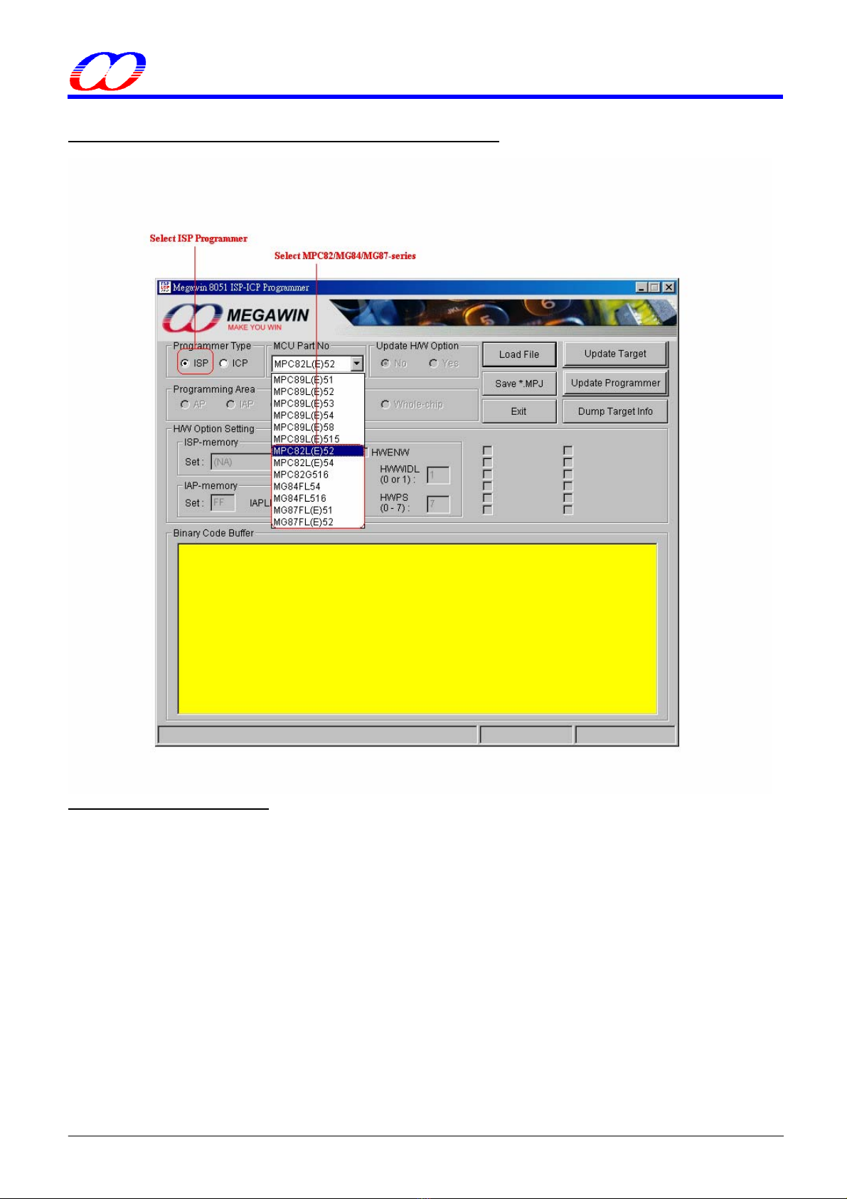
3-3-2 ISP Programmer GUI for MPC82/MG84/MG87-series
About the H/W Option Setting
For these series, the user can not update the H/W Option by ISP.
This document information is the intellectual property of Megawin Technology Co., Ltd. 10
©Megawin Technology Co., Ltd. 2008 All rights reserved.
MEGAWIN
MAKE YOU WIN
8051 ISP-ICP Programmer
User Manual, v5.41
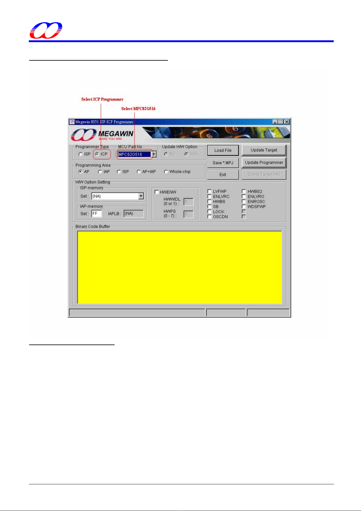
3-3-3 ICP Programmer GUI for MPC82G516
About the H/W Option Setting
The user should always configure proper H/W Option before clicking “Update Target” or “Update Programmer”.
ISP-memory:
Select the size you want.
IAP-memory:
Select the lower boundary address you want. For example, if 0x5A00 is wanted, then just key in “5A”, and the
IAP-memory lower boundary address will automatically displayed in the IAPLB box.
LVFWP:
[enabled]: Enable LVFWP (Low-Voltage Flash Write Protection) while IAP or ISP programming.
[disabled]: Disable LVFWP.
ENLVRC:
[enabled]: Enable hardware to generate low voltage reset when V30-pin voltage drops below 2.4V.
[disabled]: Disable low voltage reset.
This document information is the intellectual property of Megawin Technology Co., Ltd. 11
©Megawin Technology Co., Ltd. 2008 All rights reserved.

MEGAWIN
MAKE YOU WIN
8051 ISP-ICP Programmer
User Manual, v5.41
HWBS:
[enabled]: When power-on, MCU will boot from ISP-memory if ISP-memory is configured.
[disabled]: MCU always boots from AP-memory.
SB:
[enabled]: Code dumped on a universal Writer or Programmer is scrambled for security, but Device ID can be
read normally. It is strongly recommended that the LOCK should also be enabled when SB is enabled.
[disabled]: Not scrambled.
LOCK:
[enabled]: Code dumped & Device ID read on a universal Writer or Programmer is locked to 0xFF for security.
[disabled]: Not locked.
OSCDN:
[enabled]: Oscillating gain is reduced down for EMI reduction.
[disabled]: Normal gain.
HWBS2:
[enabled]: Like HWBS, the reset from RST-pin can also cause MCU to boot from ISP-memory.
[disabled]: Where MCU boots from is determined by HWBS.
ENLVRO:
[enabled]: Enable MCU to generate low voltage reset when VDD-pin voltage drops below 3.7V.
[disabled]: No low voltage reset.
ENROSC:
[enabled]: Enable built-in RC oscillator.
[disabled]: Disable built-in RC oscillator.
WDSFWP:
[enabled]: The special function register WDTCR will be write-protected except the bit CLRW.
[disabled]: The special function register WDTCR is free to be written by software.
HWENW (accompanied with arguments HWWIDL and HWPS[2:0]):
[enabled]: Automatically enable Watch-dog Timer by the hardware when the MCU is powered up.
It means that:
In the WDTCR register, the hardware will automatically:
(1) set ENW bit,
(2) load HWWIDL into WIDL bit, and
(3) load HWPS[2:0] into PS[2:0] bits.
For example:
If HWWIDL and HWPS[2:0] are programmed to be 1 and 5, respectively, then WDTCR will be
initialized to be 0x2D when MCU is powered up, as shown below.
[disabled]: No action on Watch-dog Timer when the MCU is powered up.
This document information is the intellectual property of Megawin Technology Co., Ltd. 12
©Megawin Technology Co., Ltd. 2008 All rights reserved.
MEGAWIN
MAKE YOU WIN
8051 ISP-ICP Programmer
User Manual, v5.41
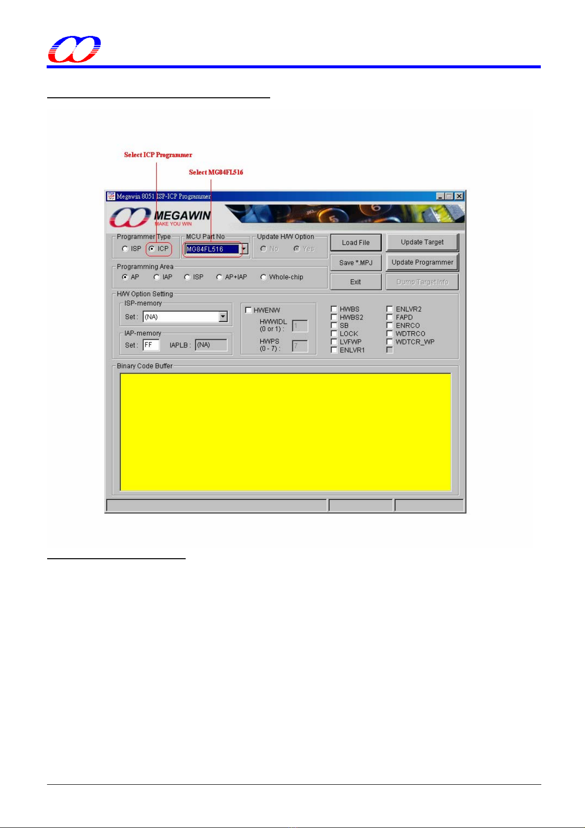
3-3-4 ICP Programmer GUI for MG84FL516
About the H/W Option Setting
The user should always configure proper H/W Option before clicking “Update Target” or “Update Programmer”.
ISP-memory:
Select the size you want.
IAP-memory:
Select the lower boundary address you want. For example, if 0x5A00 is wanted, then just key in “5A”. The IAP-
memory lower boundary address will automatically displayed in the IAPLB box.
HWBS:
[enabled]: When power-on, MCU will boot from ISP-memory if ISP-memory is configured.
[disabled]: MCU always boots from AP-memory.
HWBS2:
[enabled]: In addition to power-on-reset, the reset from RST-pin will also force MCU to boot from ISP-memory
if ISP-memory is configured.
[disabled]: Where MCU boots from is determined by HWBS.
This document information is the intellectual property of Megawin Technology Co., Ltd. 13
©Megawin Technology Co., Ltd. 2008 All rights reserved.

MEGAWIN
MAKE YOU WIN
8051 ISP-ICP Programmer
User Manual, v5.41
SB:
[enabled]: Code dumped on a universal Writer or Programmer is scrambled for security, but Device ID can be
read normally. It is strongly recommended that the LOCK should also be enabled when SB is enabled.
[disabled]: Not scrambled.
LOCK:
[enabled]: Code dumped & Device ID read on a universal Writer or Programmer is locked to 0xFF for security.
[disabled]: Not locked.
LVFWP:
[enabled]: Enable LVFWP (Low-Voltage Flash-Write Protection) while IAP or ISP programming.
[disabled]: Disable LVFWP.
ENLVR1:
[enabled]: MCU to generate low voltage reset when VDD-pin voltage drops below LVD1.
[disabled]: No low voltage reset.
ENLVR2:
[enabled]: MCU to generate low voltage reset when VDD-pin voltage drops below LVD2.
[disabled]: No low voltage reset.
FAPD:
[enabled]: Enable Flash-Auto-Power-Down to save power while normal operating.
[disabled]: Disable Flash-Auto-Power-Down.
ENROSC:
[enabled]: Enable built-in RC oscillator (6MHz).
[disabled]: Disable built-in RC oscillator.
WDTRCO:
[enabled]: Enable the RC oscillator, and select RCosc as OSCin.
[disabled]: Disable the RC oscillator, and select XTALosc as OSCin.
WDTCR_WP:
[enabled]:
If CPU runs in AP-memory, the register WDTCR will be software-write-protected except the bit CLRW.
If CPU runs in ISP-memory, the register WDTCR will be software-write-protected except the bits CLRW,
PS2, PS1 and PS0.
[disabled]: The register WDTCR can be freely written by software.
HWENW (accompanied with arguments HWWIDL and HWPS[2:0]):
[enabled]: Automatically enable Watch-dog Timer by the hardware when the MCU is powered up.
It means that:
In the WDTCR register, the hardware will automatically:
(1) set ENW bit,
(2) load HWWIDL into WIDL bit, and
(3) load HWPS[2:0] into PS[2:0] bits.
For example:
If HWWIDL and HWPS[2:0] are programmed to be 1 and 5, respectively, then WDTCR will be
initialized to be 0x2D when MCU is powered up, as shown below.
[disabled]: No action on Watch-dog Timer when the MCU is powered up.
This document information is the intellectual property of Megawin Technology Co., Ltd. 14
©Megawin Technology Co., Ltd. 2008 All rights reserved.
MEGAWIN
MAKE YOU WIN
8051 ISP-ICP Programmer
User Manual, v5.41
4 Use the ISP-ICP Programmer
4-1 Operation Modes
There are three operation modes for the ISP-ICP Programmer based on its connection conditions.
4.1.1 Mode-1: Connected between host and target system
In this condition, the ISP-ICP Programmer works with the PC-site AP being executed. Three main buttons can be
clicked: (1) The “Update Programmer” button, which is used to download the programming data (including Part
No., user’s application code and H/W option) into the non-volatile storage of the Programmer. (2) The “Update
Target” button, which further programs the new application code and H/W option into the Target MCU in addition
to those the “Update Programmer” button does. (3) The “Dump Target Info” button, which dumps the Target
Information Data described in Section 5.
The user should select correct “Part No.”, then click “Load File” to load the new application code, and configure
the H/W options (if have) before clicking the “Update Programmer” or “Update Target” button. The ISP-key can
also be used to start the ISP or ICP processing after the “Update Programmer” is completed. Of course, the user
may load the MPJ file (described in Section 4.4) to restore all the programming data to the GUI of the AP.
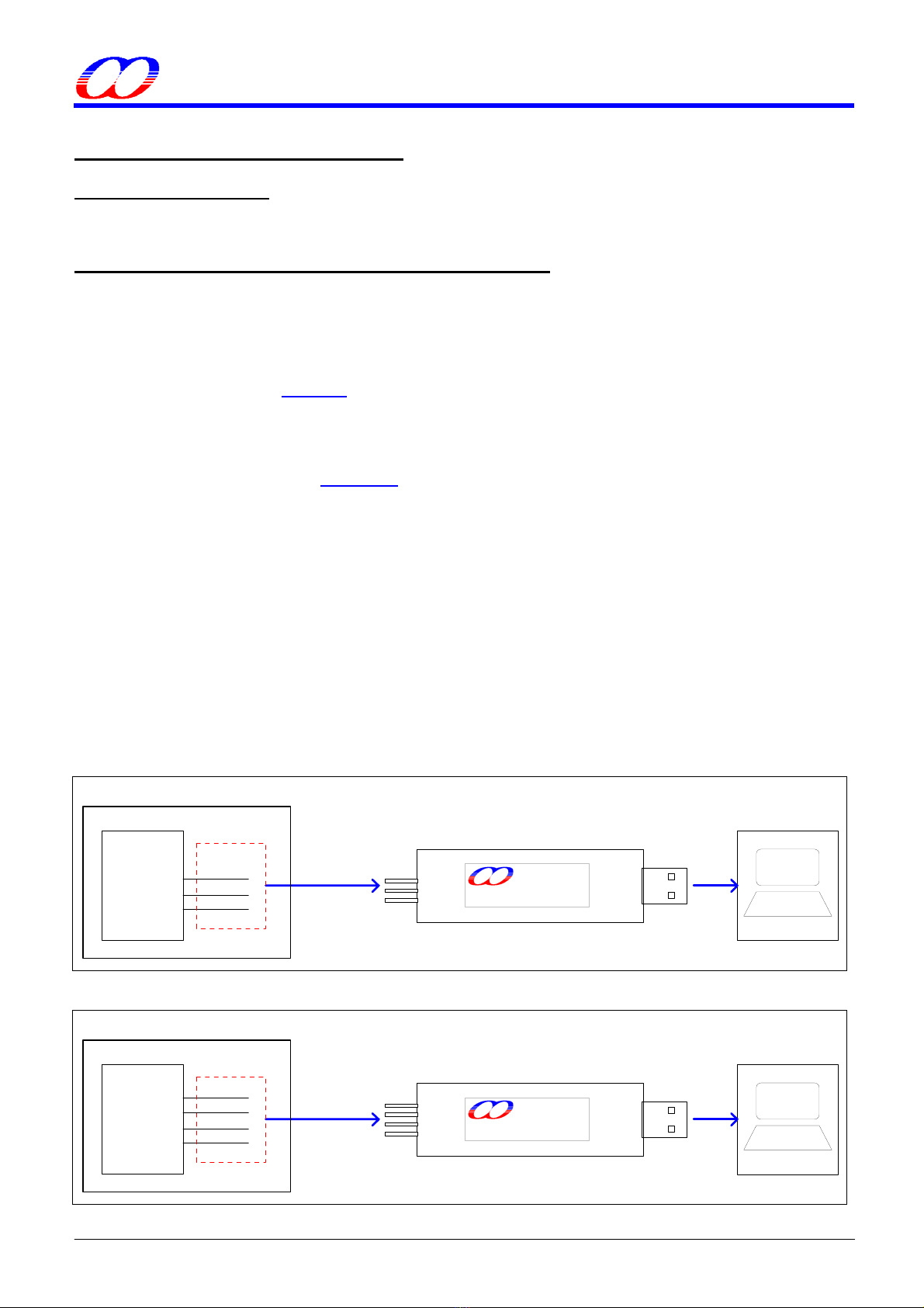
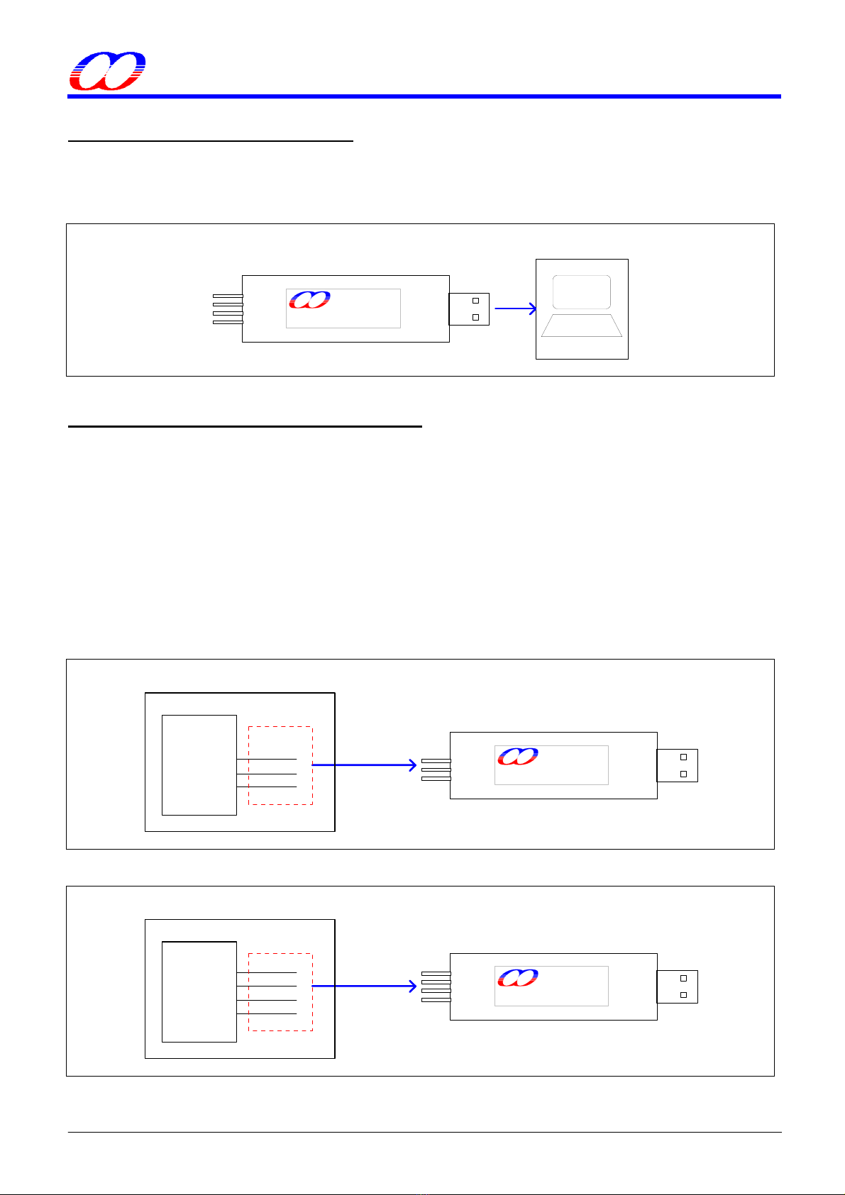
The following figures show the connection diagram:
(1) When the Programmer acts as an ISP Programmer, don’t power on the target system before connecting ok.
After connecting ok, then the user’s system can be powered on. At this time, the target MCU keeps running in the
ISP-memory for ISP processing. When ISP is finished, disconnect this Programmer from the target system to let
the target MCU run the new application code.
(2) When the Programmer acts as an ICP Programmer, the target system can be powered on before or after the
connecting. And the target MCU will automatically run the new application code without need of disconnecting
from the target system after ICP is finished.
The LEDs show the processing result. If ISP/ICP processing succeeds, the green LED will turn on, otherwise the
red LED will turn on.
When the Programmer acts as an ISP Programmer:
Act as ISP Programmer PC
USB
VCC
SDA
GND
(less than 30cm) MEGAWIN
Target System
ISP
Interface
MAKE YOU WIN
ISP Programmer
GND
VDD
VDD
VSS
P3.1
DTA
Target MCU
When the Programmer acts as an ICP Programmer:
Act as ICP Programmer PC
USB
SCL
VCC
SDA
GND
Target System
OCD_SCL
SCL
GND
VSS
ICP
Interface
VDD
VDD
OCD_SDA
SDA
Target MCU
(less than 30cm) MEGAWIN
ICP Programmer
MAKE YOU WIN
This document information is the intellectual property of Megawin Technology Co., Ltd. 15
©Megawin Technology Co., Ltd. 2008 All rights reserved.
MEGAWIN
MAKE YOU WIN
8051 ISP-ICP Programmer
User Manual, v5.41
4.1.2 Mode-2: Connected to host only
In this condition, the ISP-ICP Programmer works with the PC-site AP being executed and only the “Update
Programmer” button can be clicked. User can download the programming data into the non-volatile storage in
the Programmer for later stand-alone operation.
ISP/ICP Programmer PC
USB
SCL
VCC
SDA
GND
MEGAWIN
MAKE YOU WIN
ICP Programmer
4.1.3 Mode-3: Connected to target system only
In this condition, the Programmer works stand-alone without the AP’s intervention.
(1) When acting as an ISP Programmer, connect the Programmer to the target system before the system is
powered up. Then, power on the system, and press the ISP-key to start ISP processing. The green and red
LEDs show the processing result. Now, the user can disconnect the Programmer to let the system start running
the new application code.
(2) When acting as an ICP Programmer, connect the Programmer to the target system at any time regardless of
the system’s power state. Then press the ISP-key to start ICP processing while the system is powered on. The
green and red LEDs show the processing result. And once the processing is finished, the system will
automatically run the new application code.
When the Programmer acts as an ISP Programmer:
Act as ISP Programmer
VCC
SDA
GND
(less than 30cm) MEGAWIN
Target System
ISP
Interface
MAKE YOU WIN
ISP Programmer
GND
VDD
VDD
VSS
P3.1
DTA
Target MCU
When the Programmer acts as an ICP Programmer:
Act as ICP Programmer
SCL
VCC
SDA
GND
(less than 30cm) MEGAWIN
Target System
ICP
Interface
OCD_SCL
SCL
GND
MAKE YOU WIN
ICP Programmer
VDD
VDD
VSS
OCD_SDA
SDA
Target MCU
This document information is the intellectual property of Megawin Technology Co., Ltd. 16
©Megawin Technology Co., Ltd. 2008 All rights reserved.

MEGAWIN
MAKE YOU WIN
8051 ISP-ICP Programmer
User Manual, v5.41
4-2 Act as an ISP Programmer
4.2.1 Download Programming Data to the ISP Programmer
How to download new programming data (including application code & H/W options) into the Programmer?
Step 1: Select “Programmer Type” as ISP Programmer, and select the wanted “MCU Part No”.
Step 2: Click “Load File”, both HEX format and BIN format are acceptable, and the code size is based on its
binary format.
For MPC89L(E)51/52/53, the maximum code size is 15K-1K=14K bytes, which includes IAP data.
For MPC89L(E)54/58/515, the maximum code size is 63K-1K=62K bytes, which includes IAP data.
For MPC82L(E)52, the maximum code size is 8K-1K=7K bytes, which includes IAP data.
For MPC82L(E)54, the maximum code size is 15.5K-1.5K=14K bytes, which includes IAP data.
For MPC82G516, the maximum code size is 64K-1K=63K bytes, which includes IAP data.
For MG84FL54, the maximum code size is 16K-1K=15K bytes, which includes IAP data.
For MG84FL516, the maximum code size is 64K-1K=63K bytes, which includes IAP data.
For MG87L(E)51/52, the maximum code size is 8K-1K=7K bytes, which includes IAP data.
Where, “minus 1K” (or 1.5K for MPC82L(E)54 ) means subtracting the space of ISP-memory.
Step 3: Configure the wanted H/W Option. (Only available for MPC89-series.)
Step 4: Click “Update Programmer”.
Note: In Step 2, you can load an MPJ file (refer to Section 4.4), then Step 3 is not necessary.
4.2.2 Update the Target
How to update the target?
Step 1~3: The same as previous Step1~3..
Step 4: Click “Update Target”.
4.2.3 Dump the Contents in the Information Zone
How to dump the 256 bytes of target “Information Data”? (Please refer to Section 5)
Step 1: Select “Programmer Type” as an ISP Programmer.
Step 2: Click “Dump Target Info”.
This document information is the intellectual property of Megawin Technology Co., Ltd. 17
©Megawin Technology Co., Ltd. 2008 All rights reserved.

MEGAWIN
MAKE YOU WIN
8051 ISP-ICP Programmer
User Manual, v5.41
4-3 Act as an ICP Programmer
4.3.1 Download Programming Data to the ICP Programmer
How to download new programming data (including application code & H/W options) into the Programmer?
Step 1: Select “Programmer Type” as ICP Programmer, and select the wanted “MCU Part No”.
Step 2: Click “Load File”, both HEX format and BIN format are acceptable, and the code size is based on its
binary format.
Step 3: Configure the wanted H/W Option.
Step 4: Click “Update Programmer”.
Note: In Step 2, you can load an MPJ file (refer to Section 4.4), then Step 3 is not necessary.
4.3.2 Update the Target
How to update the target?
Step 1~3: The same as previous Step1~3..
Step 4: Click “Update Target”.
This document information is the intellectual property of Megawin Technology Co., Ltd. 18
©Megawin Technology Co., Ltd. 2008 All rights reserved.
MEGAWIN
MAKE YOU WIN
8051 ISP-ICP Programmer
User Manual, v5.41
4-4 The Megawin Project File (MPJ File)
In addition to the application code, the Programmer may program the H/W options to the target MCU at each time
the “Update Target” button (on the PC-site AP) is clicked or the ISP-key (on the Programmer) is pressed. And,
maybe the operating of application code depends on the H/W options (for example, EN6T), so the one who takes
the programming task must set the correct H/W options in addition to loading the correct application code. To
prevent from any mistake (for example, forget to set the correct H/W options), all the relevant programming
information should be saved together in one file, which we called the MPJ file.
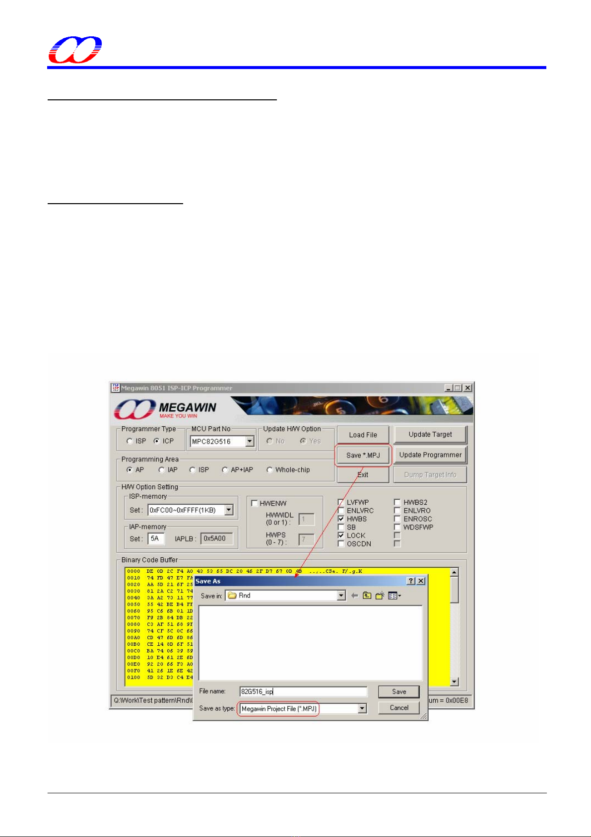
4.4.1 Save to an MPJ File
The MPJ file includes all the relevant programming information appearing on the GUI, they are:
(1) Programmer Type,
(2) MCU Part No,
(3) Control of Update H/W Option,
(4) Programming Area,
(5) H/W Option Setting, and
(6) Binary Code Buffer.
Click the button “Save *.MPJ” to save all the programming information in an MPJ file, as shown below.
This document information is the intellectual property of Megawin Technology Co., Ltd. 19
©Megawin Technology Co., Ltd. 2008 All rights reserved.

MEGAWIN
MAKE YOU WIN
8051 ISP-ICP Programmer
User Manual, v5.41
4.4.2 Load an MPJ File
Click “Load File” and select Megawin Project Files (*.MPJ) to select the MPJ file you want. When the MPJ file is
opened, all the relevant programming information will be retrieved and restored to the GUI of the AP. The
following figure shows how to open an MPJ file.
This document information is the intellectual property of Megawin Technology Co., Ltd. 20
©Megawin Technology Co., Ltd. 2008 All rights reserved.
Other manuals for 8051
1
Table of contents


