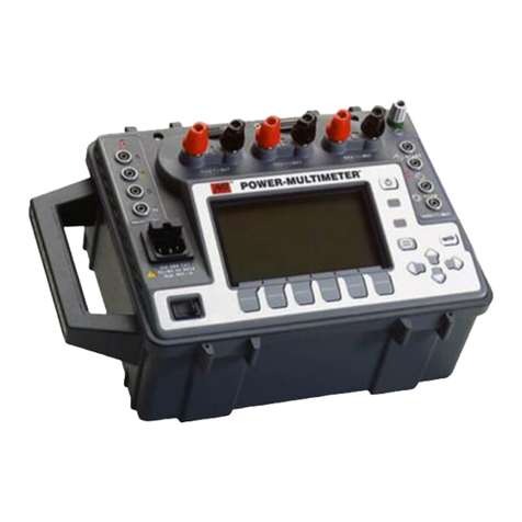
Megger PMM-2 User manual

PMM-2
POWER MULTIMETER
User Guide

PMM-2
2
IMPORTANT
This user guide, as well as the hardware and software described in it, is furnished under license, and may
be used or copied only in accordance with the terms of such license. The content of this user guide is
furnished for informational use only and is subject to change without notice. Megger assumes no
responsibility or liability for any errors or inaccuracies that may appear in this user guide.
The information and data in this user guide are proprietary. The equipment described herein may be
protected by U.S. patents. Megger specifically reserves all rights to such proprietary information as well
as rights under any patent, none of which is waived by the submission of this user guide.
Except as permitted by such license, no part of this publication may be reproduced, stored in a retrieval
system, or transmitted, in any form or by any means, electronic, mechanical, recording, or otherwise,
without the prior written permission of Megger.
Megger, the Megger logo are trademarks of Megger. All other trademarks are the property of their
respective owners.
Notice to U.S. government end users. The hardware, software and documentation are “commercial
items,” as that term is defined at 48 C.F.R. §2.101, consisting of “commercial computer software” and
“commercial computer software documentation,” as such terms are used in 48 C.F.R. §12.212 or 48
C.F.R. §227.7202, as applicable. Consistent with 48 C.F.R. §12.212 or 48 C.F.R. §§227.7202-1 through
227.7202-4, as applicable, the commercial computer software and commercial computer software
documentation are being licensed to U.S. government end users (1) only as commercial items and (2)
with only those rights as are granted to all other end users pursuant to the terms and conditions set forth
in the Megger standard commercial agreement for this software and hardware. Unpublished rights
reserved under the copyright laws of the United States. The recipient, if a government agency,
acknowledges that this user guide and the equipment described were procured with "Limited Rights" to
technical data as described in ASPR 9-203 (b).
The onboard display includes an RTOS-resident computer program. This program belongs to Megger and
contains trade secret ideas and information of Megger, written and designed at Megger, 4545 W. Davis,
Dallas, Texas 75211-3422 USA
© 2022
This document is the copyright of:
Megger Limited, 4545 W Davis Street
Dallas, Texas 75211-3422 USA
PHONE: (800) 723-2861
FAX: (214) 331-7399
www.megger.com
Megger reserves the right to alter the specification of its products from time to time without notice.
Although every effort is made to ensure the accuracy of the information contained within this document it
is not warranted or represented by Megger Limited to be a complete and up-to-date description.
For patent information about this instrument refer to the following web site: megger.com/patent

PMM-2
3
Revision history
Revision
ECN #
Date
1
87865
9/01/2022
Declaration of conformity
Hereby, Megger Instruments Limited declares that the PMM-2, manufactured by Megger Instruments
Limited described in this user guide, is following Directive 2014/53/EU. The full text of Megger
Instruments EU declarations of conformity is available at the following internet address:
Megger.com/Company/About-Us/Legal/EU declarations of conformity

PMM-2
4
Table&of&contents&
IMPORTANT ......................................................................................................................................................... 2
REVISION HISTORY ............................................................................................................................................... 3
TABLE OF FIGURES ............................................................................................................................................... 7
1.0 INTRODUCTION .............................................................................................................................................. 9
1.1 PRODUCT DESCRIPTION ............................................................................................................................................. 9
1.2 FEATURES ............................................................................................................................................................... 9
1.3 APPLICATIONS ....................................................................................................................................................... 10
1.4 MEGGER WEBSITE .................................................................................................................................................. 10
2.0 SAFETY WARNINGS AND STANDARDS ........................................................................................................... 11
2.1 WARNINGS, CAUTIONS AND NOTES ........................................................................................................................... 11
2.2 ADDITIONAL SAFETY WARNINGS ..................................................................................................................... 12
3.0 INSTRUMENT OVERVIEW .............................................................................................................................. 13
3.1 PMM-2 ONBOARD DISPLAY SCREEN AND POWER INPUT ................................................................................................ 13
3.2 INPUT POWER CORD ............................................................................................................................................... 14
3.3 TOP PANEL COMMUNICATION PORTS AND INPUT TERMINALS ........................................................................................... 15
3.4 CONFIGURATION OF PMM-2 SOFTWARE .................................................................................................................... 16
3.4.1 Configuration ............................................................................................................................................. 17
3.4.2 System configuration options .................................................................................................................... 18
3.4.2.3 Label settings .......................................................................................................................................... 18
3.4.2.3.1 Voltage character ................................................................................................................................. 19
3.4.2.4 Global settings ........................................................................................................................................ 19
3.4.2.4.1 Language ............................................................................................................................................. 19
3.4.2.4.2 Set system date and time ..................................................................................................................... 19
3.4.2.4.3 System info (information screen) ......................................................................................................... 19
3.4.2.5 Screen dimming ....................................................................................................................................... 20
3.4.2.6 Sample settings ....................................................................................................................................... 20
3.4.2.6.1 Fundamental frequency ....................................................................................................................... 20
3.4.2.6.2 Waveform capture rate ........................................................................................................................ 20
3.4.2.6.3 Pre-trigger samples .............................................................................................................................. 20
3.4.2.7 Diagnostic logging settings ..................................................................................................................... 21
3.4.3 Phase angle configuration screen .............................................................................................................. 21
3.4.4 CT/PT ratios ................................................................................................................................................ 21
3.4.6 Colors options ............................................................................................................................................. 22
4.0 GENERAL OPERATING INSTRUCTIONS ........................................................................................................... 23
4.1 SAFETY CONSIDERATIONS ......................................................................................................................................... 23
4.2 SET UP OF PMM-2 ................................................................................................................................................ 23
4.2.1 Unpack system ........................................................................................................................................... 23
4.2.2 Initial startup .............................................................................................................................................. 24
4.2.3 Battery ....................................................................................................................................................... 24
4.2.3.1 Battery charging ..................................................................................................................................... 24
4.3 MAIN STARTUP SCREEN ........................................................................................................................................... 25
4.3.1
!
Connection button ................................................................................................................................. 25
4.3.2
"
The configuration button ...................................................................................................................... 25

PMM-2
5
4.3.3
#
Report options button ........................................................................................................................... 25
4.3.4
$
Timer configuration button ................................................................................................................... 26
4.3.4.1 Timer configuration ................................................................................................................................. 27
4.3.4.1.1 Timer name .......................................................................................................................................... 27
4.3.4.1.2 Start/stop condition ............................................................................................................................. 27
4.3.4.1.2.1 Channel selection .............................................................................................................................. 28
4.3.4.1.3 Mode selection ..................................................................................................................................... 28
4.3.4.1.3.1 One-shot ............................................................................................................................................ 28
4.3.4.1.3.2 Accumulate ....................................................................................................................................... 29
4.3.4.1.3.3 Reclosing ........................................................................................................................................... 29
4.3.5
%
Binary input configuration button ......................................................................................................... 29
4.3.5.1
!
Trigger configuration button ................................................................................................................... 30
4.3.6
&
Snapshot button .................................................................................................................................... 30
4.3.8
⑦
Record button ........................................................................................................................................ 31
4.3.9
⑧
Select panels and charts to display button ........................................................................................... 31
4.3.9.1 Enable current/frequency panel .............................................................................................................. 31
4.3.9.2 Enable current panel ............................................................................................................................... 31
4.3.9.3 Enable voltage/frequency panel ............................................................................................................. 32
4.3.9.4 Enable voltage panel ............................................................................................................................... 32
4.3.9.5 Enable frequency panel ........................................................................................................................... 32
4.3.9.6 Enable power panel ................................................................................................................................. 33
4.3.9.7 Enable VA/PF panel ................................................................................................................................. 33
4.3.9.8 Enable timer panel .................................................................................................................................. 34
4.3.9.9 Charts off ................................................................................................................................................. 34
4.3.9.10 Combined waveform mode ................................................................................................................... 35
4.3.9.11 Combined waveform with binary mode ................................................................................................ 35
4.3.9.12 Polar mode ............................................................................................................................................ 36
4.3.9.13 Polar mode with binary ......................................................................................................................... 36
4.3.9.14 Split waveform mode ............................................................................................................................ 37
4.3.9.15 Harmonics mode ................................................................................................................................... 37
4.3.10
⑨
Voltage and current general settings options .................................................................................... 38
4.3.10.1 Voltage general settings options .......................................................................................................... 38
4.3.10.1.1 Voltage channel enable/disable switch ............................................................................................. 38
4.3.10.1.2 Voltage channel mode options .......................................................................................................... 38
4.3.10.1.3 Voltage channel integration cycles .................................................................................................... 39
4.3.10.1.4 Voltage channel integration seconds ................................................................................................. 39
4.3.10.1.5 Voltage channel range options .......................................................................................................... 39
4.3.10.1.6 Voltage channel trigger setting options ............................................................................................. 39
4.3.10.1.7 Voltage channel low pass filter .......................................................................................................... 40
4.3.10.1.8 Voltage channel external CT settings ................................................................................................. 40
4.3.10.2 Current general settings options ........................................................................................................... 40
4.3.10.2.1 Current channel enable/disable switch .............................................................................................. 41
4.3.10.2.2 Current channel mode options ........................................................................................................... 41
4.3.10.2.3 Current channel integration cycles ..................................................................................................... 41
4.3.10.2.4 Current channel DC integration seconds ............................................................................................ 41
4.3.10.2.5 Current channel range options ........................................................................................................... 41
4.3.10.2.6 Current channel trigger setting options ............................................................................................. 42
4.3.10.2.7 Current channel low pass filter .......................................................................................................... 42
4.3.10.2.8 Current channel external CT settings ................................................................................................. 42
4.3.10.3 Phase reference ..................................................................................................................................... 42
4.3.11
⑩
Freeze button ..................................................................................................................................... 43

PMM-2
6
4.3.12
⑪
Help ? button ...................................................................................................................................... 43
4.3.13
⑫
File folder button ................................................................................................................................ 43
4.3.14
⑬
Battery icon ........................................................................................................................................ 43
4.3.15
⑭
Graphic display screen ........................................................................................................................ 43
4.3.15.1 Graphic display zoom button ................................................................................................................ 44
4.3.16 Binary Inputs #1 and #2 status ................................................................................................................. 44
5.0 APPLICATIONS .............................................................................................................................................. 44
5.1 SINGLE-PHASE OPERATION ....................................................................................................................................... 44
5.1.1 Single-phase to neutral current and voltage example ............................................................................... 45
5.1.2 1-phase, 2-wire, 1 ½ element with CTs example ........................................................................................ 47
5.2 THREE-PHASE OPERATION ....................................................................................................................................... 48
5.2.1 Selecting the configuration ........................................................................................................................ 49
5.2.2 Measuring functions .................................................................................................................................. 49
5.2.3 Clamp-on current and potential transformer operation ............................................................................ 50
5.2.3.1 Measuring primary current with clamp-on CT ........................................................................................ 50
5.2.3.2 Verifying the ratios of CTs ....................................................................................................................... 51
5.3 TIMING TESTS ........................................................................................................................................................ 52
5.3.1 Timing test using binary inputs .................................................................................................................. 53
5.3.2 Timing test using current start ................................................................................................................... 53
5.4 TIMED DATA RECORDING ......................................................................................................................................... 54
5.5 PMM-2 software file management ............................................................................................................... 55
5.5.1 File management main screen ................................................................................................................... 56
5.5.1.1 Forms and form results folder ................................................................................................................. 56
5.5.1.2 Snapshots folder ...................................................................................................................................... 56
5.5.1.3 Recordings folder .................................................................................................................................... 57
5.5.1.4 Logs folder ............................................................................................................................................... 57
5.5.1.5 Software updates .................................................................................................................................... 57
6.0 MAINTENANCE ............................................................................................................................................. 57
6.1 GENERAL MAINTENANCE .......................................................................................................................................... 57
6.2 CLEANING ............................................................................................................................................................. 57
6.3 BATTERY ............................................................................................................................................................... 58
6.3.1 Battery status ............................................................................................................................................. 58
6.4 UPDATING PMM-2 SOFTWARE AND FIRMWARE .......................................................................................................... 58
7.0 BATTERY REPLACEMENT ............................................................................................................................... 58
8.0 SPECIFICATIONS ........................................................................................................................................... 59
9.0 ACCESSORIES ................................................................................................................................................ 62
9.1 INCLUDED ACCESSORIES ........................................................................................................................................... 62
9.2 TABLE OF OPTIONAL ACCESSORIES .............................................................................................................................. 62
10.0 CALIBRATION, REPAIR, AND WARRANTY .................................................................................................... 66
10.1 WARRANTY ......................................................................................................................................................... 66
10.2 RETURN PROCEDURE ............................................................................................................................................ 67
11.0 DECOMMISSIONING ................................................................................................................................... 67
11.1 WEEE DIRECTIVE ................................................................................................................................................ 67
11.2 PMM-2 AND BATTERY DISPOSAL ............................................................................................................................ 68

PMM-2
7
Table of figures
Figure 1: PMM-2 touch screen and power input ........................................................................................ 13
Figure 2: Communication ports and input terminals .................................................................................. 15
Figure 3: Main startup screen .................................................................................................................... 16
Figure 4: System configuration screen ...................................................................................................... 17
Figure 5: Enter new profile name ............................................................................................................... 18
Figure 6: Changing channel 4 name with the alphanumeric keyboard ...................................................... 19
Figure 7: System info screen ..................................................................................................................... 20
Figure 8: Phase Angle Configuration Setting screen ................................................................................. 21
Figure 9: CT/PT ratios input selection screen ............................................................................................ 22
Figure 10: Primary values displayed with split screen waveforms ............................................................. 22
Figure 11: Color options ............................................................................................................................. 23
Figure 12: Main startup screen identifications ........................................................................................... 25
Figure 13: Reports options – customs form available in the software ....................................................... 26
Figure 14: Timer configuration screen ....................................................................................................... 27
Figure 15: Timer start/stop conditions menu .............................................................................................. 27
Figure 16: Channel select for analog start/stop ......................................................................................... 28
Figure 17: Timer mode selection screen .................................................................................................... 28
Figure 18: Binary input configuration screen ............................................................................................. 29
Figure 19: Programmable voltage threshold setting .................................................................................. 29
Figure 20: Snapshot options screen .......................................................................................................... 30
Figure 21: Select panels to display screen ................................................................................................ 31
Figure 22: Enabled current/frequency panel .............................................................................................. 31
Figure 23: Enabled current panel ............................................................................................................... 32
Figure 24: Enabled voltage/frequency panel ............................................................................................. 32
Figure 25: Enabled voltage panel .............................................................................................................. 32
Figure 26: Enabled frequency panel .......................................................................................................... 33
Figure 27: Enabled Watts and VARs ......................................................................................................... 33
Figure 28: Enabled VA/PF (power factor) panel ........................................................................................ 33
Figure 29: Enabled timer panel .................................................................................................................. 34
Figure 30: Select chart mode screen ......................................................................................................... 34
Figure 31: Charts off screen ...................................................................................................................... 34
Figure 32: Combined waveform screen ..................................................................................................... 35
Figure 33: Combined waveform with binary screen ................................................................................... 35
Figure 34: Polar plot of 3-phase voltage and current vectors .................................................................... 36
Figure 35: Polar plot of 3-phase voltage and current vectors and binary inputs ........................................ 36
Figure 36: Split waveform screen .............................................................................................................. 37
Figure 37: Harmonics display screen ......................................................................................................... 37
Figure 38: Voltage and current general settings screen ............................................................................ 38
Figure 39: Voltage channel modes ............................................................................................................ 38
Figure 40: Voltage ranges .......................................................................................................................... 39
Figure 41: Voltage channels used to measure current via external CTs ................................................... 40
Figure 42: Current channels configuration screen ..................................................................................... 40
Figure 43: Current channel modes ............................................................................................................ 41
Figure 44: Current ranges .......................................................................................................................... 42
Figure 45: Phase reference selection list ................................................................................................... 43
Figure 46: Example zoom of I1 3rd and 5th harmonic distorted waveform ................................................ 44
Figure 47: Binary #1 and #2 graphic icons in graphic window ................................................................... 44
Figure 48: Single-phase voltage and current direct connection ................................................................. 45
Figure 49: Single-phase voltage and current using CT/PT connections .................................................... 45
Figure 50: Single-phase IA and VA with combined waveforms ................................................................. 46
Figure 51: Single-phase with split waveform option ................................................................................... 46
Figure 52: 1-phase, 2 wire, 1½ element with CTs example test connections ............................................ 47
Figure 53: 1-phase, 2 wire ,1½ element example with combined waveforms ........................................... 48
Figure 54: 1-phase, 2 wire, 1½ element example with split waveform option ............................................ 48


PMM-2
8
Figure 55: Three-phase, 4 wire, 3 element connections ............................................................................ 49
Figure 56: Example three-phase wye power measurements ..................................................................... 50
Figure 57: Current general settings screen ................................................................................................ 51
Figure 58: Example panels to display for CT testing ................................................................................. 52
Figure 59: Checking CT ratio with clamp-on CT ........................................................................................ 52
Figure 60: Example recorder capture options screen ................................................................................ 54
Figure 61: File folder main screen ............................................................................................................. 55
Figure 62: Example recording data file ...................................................................................................... 55
Figure 63: File management main screen ................................................................................................. 56
Figure 64: Example three-phase snapshot screen shot ............................................................................ 56

PMM-2
9
1.0 Introduction
This user guide contains information regarding the correct use and safe handling of the POWER
MULTIMETER Model PMM-2. This user guide can be found by pressing the “?” Help button located
on the main screen of the PMM-2 software on the onboard display of the PMM-2 unit or on the PC
version of the software. Please read the section ‘Safety Precautions’ which contains information
regarding your personal safety when using the PMM-2.
1.1 Product description
The Megger POWER MULTIMETER model PMM-2 is a next generation, state-of-the-art, portable
battery/line operated multifunction instrument for measuring AC or DC voltage, AC primary and
secondary current, DC current, power, reactive power, power factor, phase angle and frequency of a
single or three phase electrical system. The POWER MULTIMETER is easily configured to measure
the amplitude and phase angle between any voltage and current inputs. All measured quantities can
be displayed simultaneously on a user defineable, easy-to-read, color graphic display.
The unique on-board software in the POWER MULTIMETER, combined with a built-in
microprocessor-based timer, is specifically designed to ease testing and commissioning of protective
relay systems. The internal timer responds to a variety of start and stop gates, including the
application of AC or DC voltage or current, and opening or closing of dry contacts.
1.2 Features
• Battery and line operated, with an automatic built-in charger.
• Rugged, ergonomic and light weight plastic enclosure.
• 4 independent voltage and current channels, with a built-in timer. Each voltage terminal is
isolated from the signal common with an impedance of 100 kΩ (0 – 34.999 V) and 5 MΩ (35 – 1000
V) and is physically isolated from the chassis.
• Each voltage terminal is rated for 0 – 1000 V AC/DC.
• Three current terminals rated for 0 - 100 A AC/DC, one terminal to measure low current 0 - 32 A
AC/DC. Each current terminal is isolated from chassis common with an isolation voltage rating of 300
V.
• The four voltage channels can be converted to measure current using clamp-on CT’s with a
voltage input.
• Four low level 0 – 1 V BNC terminals for use with clamp-on CT’s. Includes user programmable
scaling to measure, calculate, and display AC/DC current.
• Specifically designed to ease testing and commissioning of protective relay systems.
• Simultaneously measures and displays voltage, current, phase angle, power, reactive power,
power factor, and frequency of single or three phase systems.
• Wide current and voltage operating ranges.
• Accurate phase angle measurement at very low current levels.
• Auto-ranging to reduce test time, with manual over-ride.
• Ethernet and USB data ports.

PMM-2
10
• Large, easy-to-read, high-resolution LCD touch screen display.
• Menu driven, easy to operate.
• Data storage for saving measured values.
• Programmable time data logging to memory.
• Customize C.T. ratio inputs up to a ratio of 9999:1 or 9999:5.
• Customize P.T. ratio inputs up to a ratio of 9999:1 or 9999:5.
• Harmonic measurement of any voltage or current – up to the 50th harmonic.
1.3 Applications
The PMM-2 is an ideal instrument for use in general electrical systems maintenance, in electrical
machine repairs, in protective relay testing, or in monitoring power at the electrical service entrance.
In the protective relay application area, the PMM-2 is designed to perform fast, accurate checking and
testing of protective relay and meter installations, during their commissioning and in routine
maintenance.
Also, combined with a source of voltage and/or current, PMM-2 becomes an excellent tool for testing
and calibrating various types of protective relays.
1.4 Megger website
Occasionally an information bulletin may be issued via the Megger website. This may concern new
accessories, new usage instructions or a software/firmware update. Please occasionally check on the
Megger website for anything applicable to your PMM-2 POWER MULTIMETER.
www.megger.com

PMM-2
11
2.0 Safety Warnings and Standards
This instrument has been designed for operator safety; however, no design can completely protect
against incorrect use. This instrument must be operated, used and serviced ONLY by trained and
qualified personnel. Misuse of electrical instruments can result in personal injury and damage to the
apparatus under test. Obey all applicable safety rules and regulations at all times. Electrical
circuits are dangerous and can be lethal when lack of caution and poor safety practices are used.
There are several standard safety precautions that should be taken by the operator.
2.1 Warnings, Cautions and Notes
Where applicable, internationally recognized defined IEC safety markings have been placed in the
user guide, and on the instrument, to notify the operator to refer for instructions on correct use or
safety related topics. Refer to the following descriptions and table of symbols.
Descriptions
DANGER: Indicates a dangerous situation, which could cause severe injury or death
WARNING: Indicates a potentially dangerous situation, which could cause severe injury or death
CAUTION: Indicates a situation which could lead to damage of the equipment or environment
NOTE: Indicates important instructions to perform the relevant process safely and efficiently
APPLICATION NOTE: Indicates an application of the instrument
Symbol
Description
Direct current
Alternating current
Both direct and alternating current
Earth (safety ground) terminal. This terminal must be connected to an
earth ground before making other connections to the instrument and prior
to operating it.
EU conformity. Equipment complies with current EU directives.
The crossed out wheeled waste bin placed on Megger products is a
reminder not to dispose of the product at the end of its life with general
waste.
Warning/caution, risk of electric shock. Indicates that high voltage is
present on the terminal. Use extreme caution.
Warning/caution, this symbol indicates that the operator of the instrument
must refer to the user guide for further explanation and clarification.
WARNING: Under no circumstances should the operator or technician attempt to open
or service any Megger instrument while connected to a power source. Lethal voltages are
present and may cause severe injury or death!

PMM-2
12
2.2 Additional safety warnings
The following are some additional safety related items associated with the PMM-2.
§ Trained and competent persons must only use the instrument.
§ Read and understand all safety precautions and operation instructions before attempting
to use this instrument.
§ The purpose of this equipment is limited to use as described in this user guide. Should a
situation arise that is not covered in the general or specific safety precautions please
contact Megger regional representative or Megger, Dallas Texas.
§ Safety is the responsibility of the user. Misuse of this equipment can be extremely
dangerous.
§ Always start with the power OFF, before connecting the power cord. Make
sure to connect the earth ground terminal to a suitable earth ground before
attempting to make test connections.
§ DO NOT attempt to use the unit without a safety ground connected.
§ If using the power cord, DO NOT attempt to use the unit if the power cord
ground prong is broken or missing.
§ Always use properly insulated test leads. With limited exception (the 100 A input
terminals) the optional test leads are rated for the specific input ratings of the instrument
and should be safely used and cared for. DO NOT use cracked or broken test leads.
§ Always turn the test system off before disconnecting the power cord.
§ DO NOT use the PMM-2 in an explosive atmosphere.
§ Ingress Protection on the PMM-2 is rated at IP20.
§ Observe all safety warnings marked on the equipment and in the user guide.
§ For safety related or other important topics in this user guide, like the
statement below, will be notated with the adjoined symbol. Read the topic
carefully as it may relate either to the safe operation of the instrument or the
safety of the operator.
Under no circumstances should the operator put their hand or
tools inside the instrument chassis area with the instrument
connected to a power source. Lethal voltages are present and may
cause severe injury or death!

PMM-2
13
3.0 Instrument overview
This section of the manual contains the information that you will need to set up and use the PMM-2.
3.1 PMM-2 onboard display screen and power Input
Figure 1: PMM-2 touch screen and power input
1. LCD color display ① – this 10.1-inch touch panel display provides high resolution and
features wide viewing angle technology with high luminance. The onboard display is a user-
friendly interface to control the PMM-2.
2. Incoming power/line cord ② – the input line cord terminal, are mounted on the side panel
of the PMM-2.
Input line cord
The PMM-2 is equipped with a line cord, which connects to the male
connector on the side panel. Verify the input voltage before
connecting the line cord to the power source.
NOTE: The unit can be powered from an input source with a rating of
90 to 253 VAC, 50/60 Hz. The unit automatically adjusts to the
available power if it is within the specified range.
NOTE: Figure 1 is the preferred orientation for using the PMM-2
3. Power ON/OFF switch ③!– This push-button switch is used to switch the unit on and off.
4. Earth ground terminal ④!– Use this terminal to connect chassis ground to earth ground. A
chassis ground (earth) point on the side panel is provided as the safety ground.

PMM-2
14
5. Current inputs I1 to I3 ⑤!- Three independent current inputs are provided. The correct
polarity for the phase angle measurement purposes, is indicated by the red terminal. These
inputs are either rated at 60 A or 100 A depending on the style number of the PMM-2
ordered. Maximum current is 10 A when the unit is off.
6. Current input I4: ⑥!- The I4 current input is designed to measure up to 32 A continuous.
Normally used to connect to measure the neutral current. Maximum current is 10 A when the
unit is off.
7. Voltage inputs V1 to V4 ⑦ - The single AC/DC or polyphase voltages are connected to
these terminals, as labeled. Used to measure voltages up to 1000 V phase to neutral.
3.2 Input power cord
The power cord that is supplied with the PMM-2 is based upon the power cord selection in the PMM-2
style number. Depending on the country, the power cord can come with a NEMA 5-15 male
connector, a CEE 7/7 Schuko two prong connector, come with International Color-Coded pig-tail
wires (light blue, brown and green with yellow stripe) with the insulation jacket stripped ready for
installation of the appropriate male connector, or the UK power cord, see the following example cord
descriptions and associated part numbers.
North American power cord (part number 6828)
Continental Europe power cord (part number 90015-268)
The International Color Code power cord (part number 90015-269) is ready for wiring to
the appropriate plug (depending on country). The following colors apply, Brown = Line, Blue =
Neutral and Green/Yellow = Ground.
UK power cord (part number 90015-270)

PMM-2
15
3.3 Top panel communication ports and input terminals
Figure 2: Communication ports and input terminals
1. USB interface terminals ① - there are two Type A and one Type B USB terminals
available. The USB 2.0 Interface requires a Type B “downstream” connector and is primarily
used as a communication and control port when used with Megger software. A USB cable is
not provided with the test set or in the optional accessories. For computer control, an
Ethernet cable is provided. However, should the user desire to use the USB port any
standard USB A/B cable will work with the unit.
2. IN/OUT Ethernet Ports ② are 10/100BaseTX ports. The IN port is the primary PC
connection port. This port supports MDI/MDI-X auto cross over configuration, which means
both standard and “crossover” Ethernet cables may be used. This port provides the optimal
method for downloading files and updating the unit’s firmware as required. The PMM-2
comes standard with a crossover cable. The OUT port is for future use.
3. Binary inputs 1 and 2 ③ –The binary inputs 1 and 2 will accept a voltage range of 1 to 300
VAC, or 1 to 250 VDC, or dry normally open/normally closed contacts. The binary input #1
voltage threshold is programmable from 1 to 150 V AC/DC, or a TTL fixed voltage level of
2.7 V. Binary input #2 has a TTL fixed voltage level of 2.7 V. These terminals are used with
the digital timer to start and stop the timing operations.
4. BNC clamp-on CT channel inputs CT1 to CT4 ④ - Four inputs are provided for use with
clamp-on CTs to measure primary current with a low voltage output. An arrow on the current
clamp indicates the direction of the load. See section 5.2.3 Clamp-on current and potential
transformer operation for more details.
Maximum input voltage rating of CT1 to CT4 is 1 V.
5. Current inputs I1 to I3 ⑤ - Three independent current inputs are provided. The correct
polarity, for the phase angle measurement purposes, is indicated by the red terminal. These
inputs are either rated for 60 A or 100 A depending on the style number ordered.
6. Current input I4 ⑥ - The I4 current input is designed to measure up to 32 A continuous.
Normally used to connect to measure the neutral current.
7. Voltage inputs V1 to V4 ⑦ - The single AC/DC or polyphase voltages are connected to
these terminals, as labelled. Used to measure voltages up to 1000 V phase to neutral.

PMM-2
16
3.4 Configuration of PMM-2 software
The PMM-2 software is the manual control and user interface for the unit. All manual entries will be
made through the touch screen of the PMM-2, or the software installed on a PC. Before connecting
power to the unit, make sure the PMM-2’s POWER ON/OFF switch is in the OFF position (switch
flush with the bezel). Plug the unit line cord into an appropriate power source, connect the safety
ground terminal to an appropriate earth ground, and turn the POWER ON/OFF switch to ON (press
the button in, the button ring will light up). The PMM-2 unit will go through its power up sequence, and
in ± 30 seconds the main startup screen will appear.
Figure 3: Main startup screen
In the upper left-hand corner, is the unit connection button . When using the PMM-2 without a
PC the connection will happen automatically and the user should not need to select this button for
connection. When connecting the PMM-2 with a PC the user will need to launch the PMM-2 software
and once launched a pop-up window will show the IP address, the serial number of the unit and the
time since boot up (see Figure 3). Highlight the appropriate unit and select the “connect” button to
establish connection with the PMM-2.

PMM-2
17
Figure 3: Main startup screen (PC)
3.4.1 Configuration
Pressing the Configuration button will allow the user to configure the PMM-2 hardware and
PMM-2 software by displaying tabs for; System configuration, Phase settings display configurations,
CT/PT settings configurations, and Chart color options for grid, voltage and current phasors and
waveform traces, see figure 4.
3.4.1.1 Screen exit
To exit the Configuration screen and return to the previous screen press the green check button
(you will see this same button on other screens).
Figure 4: System configuration screen

PMM-2
18
3.4.2 System configuration options
This section of the manual will describe the System, Phase, CT/PT, and Colors configurations in the
PMM-2 software.
3.4.2.1 Virtual alphanumeric keyboard
The virtual alphanumeric keyboard will automatically appear in appropriate touch screen windows to
allow the entry of ASCII text. This keyboard is used to enter names for user defined profiles, change
the “neutral” channel name, timer inputs, file names. See the following sections for examples
3.4.2.2 Configuration profile options
Found in the system configuration settings section, the system profile defaults to “Factory Default.”
However, the user can customize the system settings profile and save a new profile by pressing the
“Save As” button and giving it a name. Touch the line associated with the “Profile Name” and a virtual
keyboard will appear, enter a name, and then press the enter key. In the PC version of the software
the user will need to click in the “Profile Name” box, enter a name and then click the green check
mark.
Figure 5: Enter new profile name
The system configuration settings profile can be updated or deleted by pressing the appropriate
buttons.
3.4.2.3 Label settings
Found in the system configuration settings section; this button allows the user to set labels for each
phase; ABC, RST, XYZ, or 123. Channel 4 defaults to N for neutral. However, the user can change
the label by pressing on the “N” and an alphanumeric keyboard will appear for the user to enter a
label and then press the enter key. In the PC version of the software the user will need to click in the
“Channel 4” box and enter a name or a label.

PMM-2
19
Figure 6: Changing channel 4 name with the alphanumeric keyboard
NOTE: To save the new labels, press the “Save As” in the profile window and give the new profile a
name.
3.4.2.3.1 Voltage character
The voltage character is used to define and label the voltage channels and can be either V or U.
Press the appropriate button to change to the preferred character. Be sure to press the “Save As” in
the profile window or “Save” to update the current profile to save the changes.
3.4.2.4 Global settings
In the “Global Settings” window the user will find the option to select a specific language, setting the
internal System Date and Time, and View System Information.
3.4.2.4.1 Language
Found in general settings; this button allows the user to select the desired displayed language
(English, French, Spanish and German). The factory default is English but may be changed to
Spanish or German.
3.4.2.4.2 Set system date and time
Press the Internal button to reset the Date and Time in the PMM-2 software. This information is
critical for saving recorded values in the unit internal file manager.
3.4.2.4.3 System info (information screen)
The “System Info” is found in “Global settings.” Pressing the “System Info” button will display the unit
serial number, model number, IP address, software and firmware versions, bootloader version, and
versions of DSP, voltage (VPMM) and current (IPMM) circuit boards.

PMM-2
20
Figure 7: System info screen
NOTE: This information is useful when calling Megger for service or technical support related issues.
This is also the screen that you use to update the PMM-2 system, see section 6.4 for instructions.
3.4.2.5 Screen dimming
In this section of the “System Configuration” screen the user can set an idle time in minutes for when
the unit is on battery or mains power. To save battery power and extend the operating time, the
screen will automatically dim based upon the user defined idle time setting. In the “Brightness (0 –
100)” the brightness of the screen can be set based on a percentage.
3.4.2.6 Sample settings
The “Sampled Settings” box contains the “Fundamental Frequency” button, the “Waveform Capture
Rate” button and the “Pre-trigger Samples” button.
3.4.2.6.1 Fundamental frequency
In the default “Detected” setting, the PMM-2 will measure and determine the input line frequency and
automatically set the default fundamental frequency to the measured line frequency. To measure
harmonics when using the battery, without the mains line cord connected, the user will need to select
the fundamental frequency of the sources you are measuring. Choices are 50 Hz, 60 Hz, and 400 Hz.
3.4.2.6.2 Waveform capture rate
In the default “7.2 kHz” setting, the PMM-2 will sample the waveforms at a rate of 7.2 kHz (144
samples per second at 50 Hz or 120 samples per second at 60 Hz). When making a recording of
data, the slower the sampling rate the more data can be captured and saved to internal memory. The
higher sampling rates may be needed for higher resolution of the recorded data. Other sampling rates
that are available are 3.6, 4.8, 9.6, 14.4 and 28.8 kHz. To measure harmonics, see section 4.3.9.15, it
is recommended to use the 28.8 kHz sampling rate.
3.4.2.6.3 Pre-trigger samples
The “Pre-trigger Samples” is defaulted to 500 and will be the time used to record/capture data before
a trigger condition is reached. As an example: The PPM-2 samples at 28.8 kHz and with the default
value of 500 the time for the pre-trigger will be: 1/28800*500 = 17.36 ms
Table of contents
Other Megger Multimeter manuals

Megger
Megger AVO300 Series User manual

Megger
Megger BMM2500 User manual

Megger
Megger AVO 830 User manual

Megger
Megger MFT1500/2 User manual

Megger
Megger PMM-1 User manual

Megger
Megger M8035 User manual

Megger
Megger BM8 User manual

Megger
Megger MFT1500/2 User manual

Megger
Megger M8035 User manual

Megger
Megger AVO410 User manual