Meggitt Whittaker C327598 User manual

NOTICE: PROPRIETARY INFORMATIONOF WHITTAKER CONTROLS,INC., A BUSINESS UNIT OF MEGGITT PLC.
THE INFORMATION CONTAINED IN THIS DOCUMENT IS DISCLOSED IN CONFIDENCE. IT IS THE PROPERTY OF
WHITTAKER CONTROLS, AND SHALL NOT BE USED, DISCLOSED TO OTHERS, OR REPRODUCED IN WHOLE
OR IN PART WITHOUT THE EXPRESS WRITTEN CONSENT OF WHITTAKER CONTROLS. IF CONSENT IS GIVEN
THIS NOTICE SHALL APPEAR IN ANY SUCH REPRODUCTION.
REVISION 1.1 – 12/01/2003
Installation and
Operation Manual
PRESSURE TRANSDUCER
SPOOL ASSEMBLY
CLASS 600
PART NUMBERS:
C327598
C327598-1
C327599
C327599-1
C327600

WHITTAKER CONTROLS, INC.
A MEGGITT PLC COMPANY
INSTALLATION AND OPERATION MANUAL
PRESSURE TRANSDUCER SPOOL ASSEMBLY
C327598 CC327599 CC327600
INDUSTRIAL PRODUCTS GROUP Revision 1.1 12/01/2003 Page A
LIST OF EFFECTIVE PAGES
On a revised page, the portion of text or illustrations affected by the change is indicated by a vertical line
in the outer margin of thepage. When a revision is issued, the entire document is reissued withthecurrent
revision number and date shown on all pages. For major revisions, the basic number is incremented. For
minor revisions, the number following the decimal is incremented. Dates of issue for original and sub-
sequent revisions are as follows:
Original 1.0 ...........................................09/01/2003
Revision 1.1 ...........................................12/01/2003
The total number of pages in this technical document is 14 consisting of the following:
Title, A, 1 – 12
TABLE OF CONTENTS
SUBJECT PAGE
Introduction .......................................................................4
Description and Operation ...........................................................7
Installation ......................................................................12
LIST OF ILLUSTRATIONS
FIGURE PAGE
1 Pressure Transducer Spool Assembly ..........................................8
LIST OF TABLES
TABLE PAGE
1 Specifications and Characteristics .............................................6
2 Leading Particulars ........................................................ 11

WHITTAKER CONTROLS, INC.
A MEGGITT PLC COMPANY
INSTALLATION AND OPERATION MANUAL
PRESSURE TRANSDUCER SPOOL ASSEMBLY
C327598 CC327599 CC327600
INDUSTRIAL PRODUCTS GROUP Revision 1.1 12/01/2003 Page 1
IMPORTANT SAFETY INSTRUCTIONS
SAVE THESE INSTRUCTIONS!
This manualcontains importantinstructions that shouldbefollowed during installation andoperation ofthe
Pressure Transducer Spool Assembly. The following are general safety precautions that are not related
to specific procedures andtherefore do notappear elsewhere inthis publication. These are recommended
precautions that personnel must understand and apply during many phases of maintenance.
Safety Alert Symbols
Safetyalertsymbolsareusedinthis manualtoidentifypotentialorimmediatepersonalinjuryhazards. The
safety alert symbol words are explained below:
DANGERindicatesanimminentlyhazardoussituationwhich,ifnot
avoided, will result in injury or serious injury.
WARNINGindicatesapotentially hazardoussituation which,ifnot
avoided, could result in injury or serious injury.
CAUTION indicates a potentially hazardous situation which, if not
avoided, may result in minor or moderate injury.
CAUTION used without the safety alert symbol indicates a poten-
tially hazardous situation which, if not avoided, may result in pro-
perty damage.
WEAR PROTECTIVE CLOTHING
!Wear protective clothing (gloves, apron, etc.) approved for the materials and tools being used.
USE APPROVED SAFETY EQUIPMENT
!When cleaners are being used, approved explosion-proof lights, blowers, and other equipment must
be used. Make sure that fire fighting equipment is readily available and in working order.

WHITTAKER CONTROLS, INC.
A MEGGITT PLC COMPANY
INSTALLATION AND OPERATION MANUAL
PRESSURE TRANSDUCER SPOOL ASSEMBLY
C327598 CC327599 CC327600
INDUSTRIAL PRODUCTS GROUP Revision 1.1 12/01/2003 Page 2
GIVE CLEANERS SPECIAL CARE
!Keepcleanersinspecial polyethylene bottles orin safetycansandinminimumquantities.Discard soil-
ed cleaning rags into safety cans.
Equipment Safety Information
The following safety information briefly discusses hazards peculiar to the equipment, which are likely tobe
encountered during maintenance activity.
INSTALLATION PRECAUTIONS
!The design of the piping must provide adequate pressure and temperature protection to prevent ex-
ceeding the limits of the system or components.
!Flanged Piping Connections
CMake sure that the component orientation is correct and install the spool in-line with the flanges.
Make sure that the piping flanges are properly positioned and spaced. Do not force the piping in
order to fit the valve or other mating component. Do not use the flange bolting to pull the piping into
the proper position.
CInstall the gaskets and the bolting, and torque per ANSI or API requirements.
CRe-torque the flange closure bolts after the first exposure to elevated temperature.
!Make sure that the system operates correctly after installation.
MAINTENANCE PRECAUTIONS
!Do not loosen any fasteners or attempt to removal the spool from the line until all pressure is isolated
and released from the system.
GENERAL OPERATING LOCATION PRECAUTIONS
!Duringandafteroperation,allofthesystemcomponentsarehot.Touching hotcomponentscancause
painful injury.
!Use only authorized replacement parts or hardware.
!Observe proper Lock-Out/Tag-Out procedures when working on the system and make sure that per-
sonnel protection equipment such as electrical grounds are installed.

WHITTAKER CONTROLS, INC.
A MEGGITT PLC COMPANY
INSTALLATION AND OPERATION MANUAL
PRESSURE TRANSDUCER SPOOL ASSEMBLY
C327598 CC327599 CC327600
INDUSTRIAL PRODUCTS GROUP Revision 1.1 12/01/2003 Page 3
!Make sure that all of the electrical wiring is properly terminated. Make sure that all of the wire terminals
are securely connected.
!Avoid hazardous voltage situations that can result from unsafe conditions such as, but not limited to
the following:
CImproper grounding
CHandling electrical leads or devices with wet hands or on wet ground
CDamaged electrical wire insulation
CImproper connection or re-connection of the power terminals.
CShort circuits to ground
OPERATION AND MAINTENANCE OF HIGH PRESSURE COMPRESSED GAS SYSTEMS
!Protect all gas lines from damage or puncture. Do not operate the system if a gas leak is detected –
this could indicate a loose or damaged high pressure fitting.
!Do not use flammable solvents for cleaning parts.
!Check for tools, rags, or loose parts left in the area before resuming operation.
!Do not attempt to remove the spool from the system without first isolating it from the line pressure and
venting all of the trapped internal pressure.

WHITTAKER CONTROLS, INC.
A MEGGITT PLC COMPANY
INSTALLATION AND OPERATION MANUAL
PRESSURE TRANSDUCER SPOOL ASSEMBLY
C327598 CC327599 CC327600
INDUSTRIAL PRODUCTS GROUP Revision 1.1 12/01/2003 Page 4
INTRODUCTION
1. Purpose of Manual
A. This technical manual contains instructions for Installation and shop maintenance of the Pres-
sureTransducer SpoolAssembly (spool).Thismanualisintendedtoprovideinformation insuf-
ficient detail to permit proper installation of the equipment.
B. The spool assemblies operate as components of a fuel metering system in conjunction with an
electronicenginecontrol system tocontrol delivery ofnaturalgas toa gasturbine engine.Refer
to Table 1 for specifications/characteristics.
2. Revision Service
This manual will be revised as necessary to show the current information.
3. Weights and Measurements
Weights and measurements in this manual are expressed in both English (U.S. customary) and
Metric (SI) units.
4. Scope of Manual
The technical manual is divided as follows:
Introduction – Describes the purpose and scope of this manual.
DescriptionandOperation–Containsaphysicaldescriptionoftheequipmenttogetherwithexplan-
ations of its operation and component functions and characteristics.
Installation – Provides information for installing, connecting, and preparing the equipment for use.

WHITTAKER CONTROLS, INC.
A MEGGITT PLC COMPANY
INSTALLATION AND OPERATION MANUAL
PRESSURE TRANSDUCER SPOOL ASSEMBLY
C327598 CC327599 CC327600
INDUSTRIAL PRODUCTS GROUP Revision 1.1 12/01/2003 Page 5
5. Symbols and Abbreviations
Symbols and abbreviations used in this technical manual are as follows:
AWG American Wire Gage
C Centigrade (Celsius)
DC Direct current
F Fahrenheit
Hz Hertz
kg Kilogram
kg/s Kilograms/second
kPa KiloPascal
kPad KiloPascal, differential
kPag KiloPascal, gage
LVDT Linear variable differential transformer
mm Millimeter
Nm Newton-meter
NPT National Pipe Thread
P/N Part Number
psi Pounds per square inch
psia Pounds per square inch, absolute
psid Pounds per square inch, differential
psig Pounds per square inch, gage
SPDT Single-pole, double-throw
VDC Volts direct current

WHITTAKER CONTROLS, INC.
A MEGGITT PLC COMPANY
INSTALLATION AND OPERATION MANUAL
PRESSURE TRANSDUCER SPOOL ASSEMBLY
C327598 CC327599 CC327600
INDUSTRIAL PRODUCTS GROUP Revision 1.1 12/01/2003 Page 6
Table 1. Characteristics/Specifications
Applications ..........................................Gas Turbine Engine Fuel Systems
Service Fluid .......................................... Natural Gas (per MID-TD-0000-1)
Temperatures
Normal Ambient ....................................... –54 to 104°C (–65 to 220°F)
Natural Gas .......................................... –40 to 149°C (–40 to 300°F)
DESCRIPTION WHITTAKER
PART NUMBER HAZARDOUS AREA RATING
Pressure Transducer Spool Assembly C327598 N/A
C327598-1 CE-PED certified
C327599 N/A
C327599-1 CE-PED certified
C327600 N/A

WHITTAKER CONTROLS, INC.
A MEGGITT PLC COMPANY
INSTALLATION AND OPERATION MANUAL
PRESSURE TRANSDUCER SPOOL ASSEMBLY
C327598 CC327599 CC327600
INDUSTRIAL PRODUCTS GROUP Revision 1.1 12/01/2003 Page 7
DESCRIPTION AND OPERATION
1. Description (Refer to Figure 1)
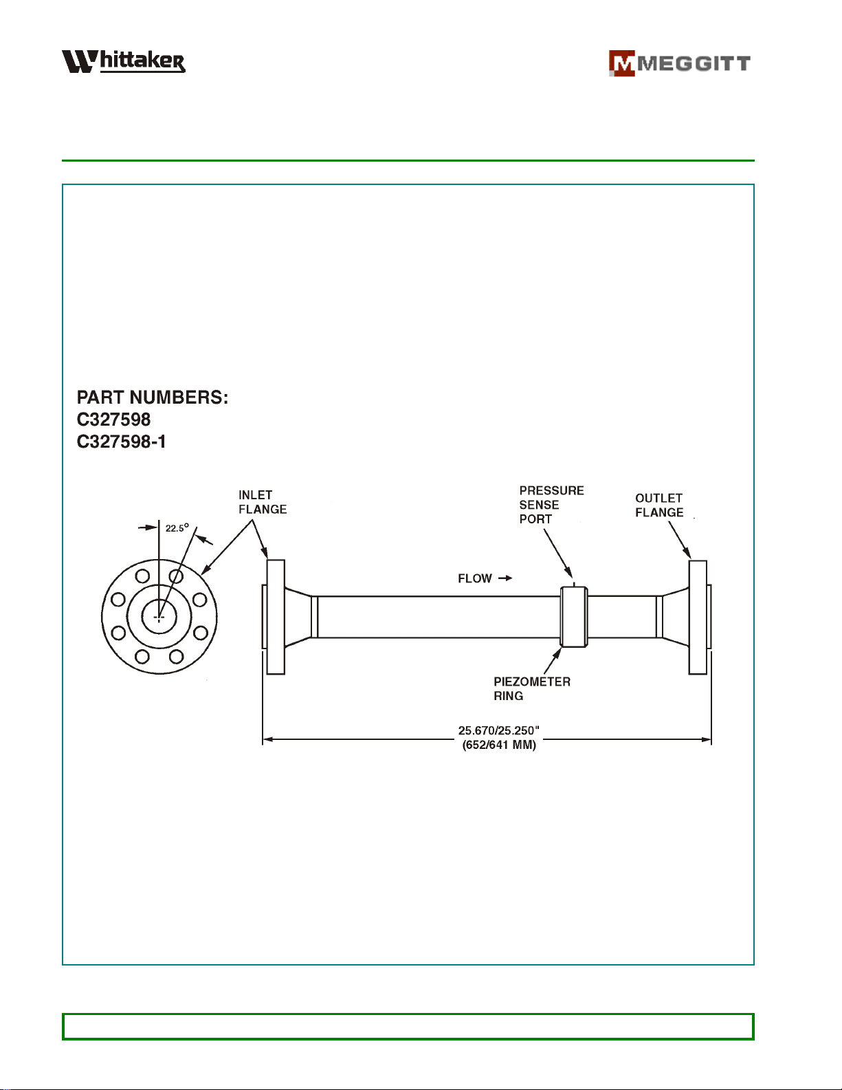
A. The Pressure Transducer Spool Assembly (spool) consists of a straight pipe section with bolt
flanges. It is used to connect components of a fuel metering system for a turbine engine. The
spool includes a piezometer ring with a pressure sense NPT port which may be connected to a
suitable pressure measuring device to accurately monitor the fuel pressure in the upstream line.
B. The spool types covered in this manual are as follows:
Gas Metering Valve Inlet Spool – Part Numbers C327598 and C327598-1 (2 Inch Outlet)
Gas Metering Valve Outlet Spool – Part Numbers C327599 and C327599-1 (1-1/2 Inch Outlet)
Gas Metering Valve Outlet Spool – Part Number C327600 (2 Inch Inlet)
2. Operation
A. The pressure of the gas fuel flowing through the line upstream of a fuel metering valve may be
accuratelymonitoredbyconnectingasuitablepressuremeasuringdevice tothepiezometer ring
pressure sense port of the spool. The ring consists of eight pressure tappings equally spaced at
45° intervals round the circumference of the pipe section. They are joined by the circular ring
which is connected to the pressure measuring device. By this means, false readings due to
irregular flow can be avoided. If the pressure on one side of the pipe is relatively high, the
pressure on the opposite side is generally correspondingly low; with the piezometer ring a mean
value is obtained.
B. For P/N C327599 and C327599-1, the piezometer ring is part of the outlet flange.
C. For P/N C327600, the spool configuration is based on the part numbering system defined in
Figure 1, Sheet 3. For complete details of the features available, refer to Figure 1, Sheet 3.
3. Leading Particulars (Refer to Table 2)
WHITTAKER CONTROLS, INC.
A MEGGITT PLC COMPANY
INSTALLATION AND OPERATION MANUAL
PRESSURE TRANSDUCER SPOOL ASSEMBLY
C327598 CC327599 CC327600
INDUSTRIAL PRODUCTS GROUP Revision 1.1 12/01/2003 Page 8
Figure 1. Pressure Transducer Spool Assembly (Sheet 1 of 3)

WHITTAKER CONTROLS, INC.
A MEGGITT PLC COMPANY
INSTALLATION AND OPERATION MANUAL
PRESSURE TRANSDUCER SPOOL ASSEMBLY
C327598 CC327599 CC327600
INDUSTRIAL PRODUCTS GROUP Revision 1.1 12/01/2003 Page 9
Figure 1. Pressure Transducer Spool Assembly (Sheet 2 of 3)

WHITTAKER CONTROLS, INC.
A MEGGITT PLC COMPANY
INSTALLATION AND OPERATION MANUAL
PRESSURE TRANSDUCER SPOOL ASSEMBLY
C327598 CC327599 CC327600
INDUSTRIAL PRODUCTS GROUP Revision 1.1 12/01/2003 Page 10
Figure 1. Pressure Transducer Spool Assembly (Sheet 3 of 3)

WHITTAKER CONTROLS, INC.
A MEGGITT PLC COMPANY
INSTALLATION AND OPERATION MANUAL
PRESSURE TRANSDUCER SPOOL ASSEMBLY
C327598 CC327599 CC327600
INDUSTRIAL PRODUCTS GROUP Revision 1.1 12/01/2003 Page 11
Table 2
Leading Particulars
Service Fluid ........................................................ Natural Gas
Applications
P/N C327598 and C327598-1 ..................... Inlet Spool for Gas Metering Valve
P/N C327599 and C327599-1 .................... Outlet Spool for Gas Metering Valve
P/N C327600 ................................. Inlet Spool for Gas Metering Valve
Performance Data
Pressures
Normal .................................200 to 700 psig (1 400 to 4 800 kPag)
Proof .............................................. 900 psig (6 200 kPag)
External Leakage ................... None at 1250 to 1300 psig (8 600 to 9 000 kPag)
Flanges
P/N C327598, C327598-1 and C327600
Inlet and Outlet ............................... 2-Inch, ANSI B16.5, CL600 RF
P/N C327599 and C327599-1
Inlet ........................................ 2-Inch, ANSI B16.5, CL600 RF
Outlet .................................... 1-1/2-Inch, ANSI B16.5, CL600 RF
Pressure Sense Port
P/N C327598, C327598-1 and C327600 ...............................3/8-18 NPT
P/N C327599 and C327599-1 ........................................1/4-18 NPT
Weight
P/N C327598 and C327598-1 .................................31pounds (14,1 kg)
P/N C327599 and C327599-1 ..................................21pounds (9,5 kg)
P/N C327600 .............................................24pounds (10,9 kg)

WHITTAKER CONTROLS, INC.
A MEGGITT PLC COMPANY
INSTALLATION AND OPERATION MANUAL
PRESSURE TRANSDUCER SPOOL ASSEMBLY
C327598 CC327599 CC327600
INDUSTRIAL PRODUCTS GROUP Revision 1.1 12/01/2003 Page 12
INSTALLATION
1. General
This section contains information on installation of the spool assembly in the fuel gas system.
2. Installation
A. Positionthepressuresenseportforconvenientconnectiontothepressuresensemonitoringline.
B. The tightening torque for the flange attaching nuts/studs should be within 70 to 90 foot-pounds
(95 to 122 Nm).
C. For P/N C327598, C327598-1 and C327600, the tightening torque for the pressure sense fitting
should be within 28 to 30 inch-pounds 3,2 to 3,4 Nm).
D. For P/N C327599 and C327599-1, the tightening torque for the pressure sense fitting should be
within 12 to 14 inch-pounds (1,4 to 1,6 Nm).
This manual suits for next models
4
Other Meggitt Transducer manuals


