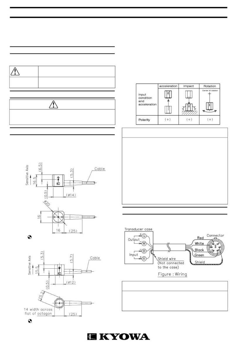
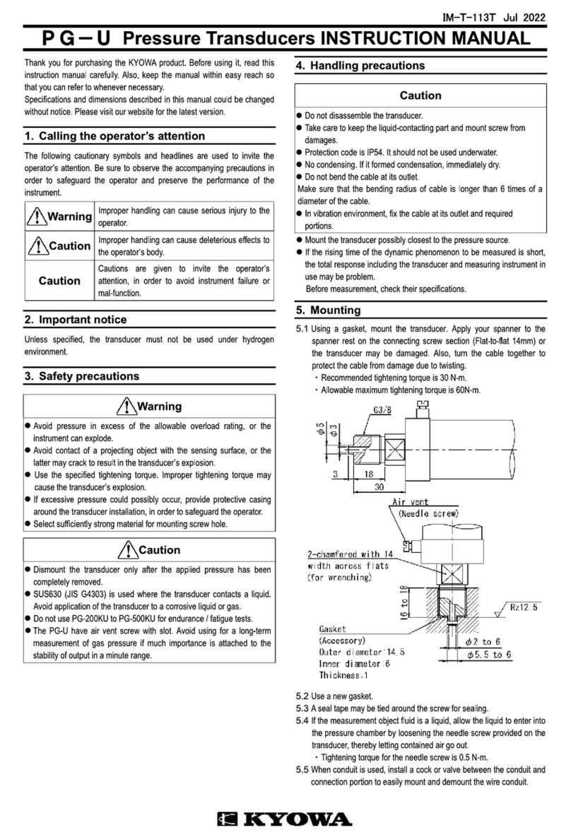
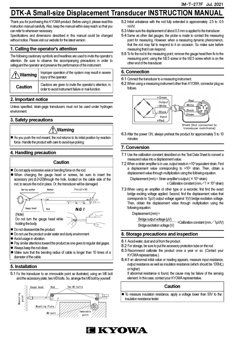
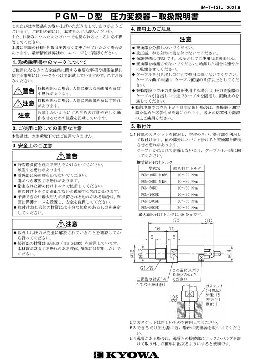
KYOWA PHF-S-SA4 User manual

IM-T-274D 2021.9
PHF-S-SA4型 圧力変換器-取扱説明書
このたびは本製品をお買い上げいただきまして,ありがとう
ございます。ご使用の前には,本書を必ずお読みください。
また,お読みになったあとは,いつでも見られるところに必
ず保管してください。
本書に記載の仕様・外観は予告なく変更させていただく場合
があります。最新情報は弊社ホームページをご確認ください。
1.
取扱説明書中のマークについて
ご使用される方の安全確保に関する重要な事項や機能確保に
関する事項にマークをつけて記載しています。必ずお読みく
ださい。
警告
取扱を誤った場合,人体に重大な悪影響を及
ぼす恐れがあります。
注意
取扱を誤った場合,人体に悪影響を及ぼす恐
れがあります。
注意
故障しないようにするための注意や正しく
動作させるための注意を記載しています。
2.
ご使用に際しての重要な注意
本製品は,水素環境下ではご使用できません。
3.
安全上のご注意
警告
許容過負荷を超える圧力をかけないでください。破裂する
恐れがあります。
受感部に突起物をあてないでください。傷がつき破裂する
恐れがあります。
指定された締め付けトルクで使用してください。締め付け
トルクが適正でないと破裂する恐れがあります。
予測できない過大圧力が負荷される可能性がある場合は,
周囲に保護ケースを設置し,安全を確保してください。
取り付けねじ穴部の材質には十分な強度のあるものを選
定してください。
注意
取り外しは圧力が完全に解放されていることを確認して
から行ってください。
接液部の材質は SUS630(JIS G4303)を使用しています。
本材質が腐食する恐れのある液体,気体には使用しないで
ください。
4.
使用上のご注意
注意
変換器を分解しないでください。
取り付けねじ部に傷を付けないでください。
変換器を結露させないでください。結露してしまった場合
は,速やかに乾燥させてください。
ケーブルを引き出し口付近で強引に曲げないでください。
ケーブル曲げ半径は,ケーブル外径の10倍以上としてく
ださい。
振動環境下で使用する場合は,ケーブル引き出し口付近で
ケーブルを固定し,振動止めを施してください。
できるだけ圧力源に近い場所に変換器を取り付けてくださ
い。
動的現象での立ち上がり時間が短い場合は,変換器と測定
器を含めた応答性が問題となります。各々の応答性を確認
の上,ご使用ください。
5.
取り付け
5.1 外形寸法
5.2 取り付け部にはOリング溝を加工してください。
Oリング(AS568 010)
太さ:φ1.78±0.07
内径:φ6.07±0.12
取付側加工例
5.3 取り付けは,ねじ部(5/16-24UNF)根本に付属のOリング
(AS568 010)をはめ込んでから行ってください。
※取り付け取り外しは,本体のスパナかけ部(六角対辺
12mm)を用いて行ってください。他の部分にスパナを掛
けると変換器を破損させる恐れがあります。
5.4 取り付け取り外しの際は,本体のみを回さずにケーブル
と一緒に回してください。
6.
接続・測定
6.1 変換器をひずみ測定器に接続します。
6.2 変換器,コネクタの配線は以下の通りです。
シールド線は変換器本体に接続されていません。
6.3 約 5 分,ヒートランを行ってから測定を開始してくださ
い。

ホームページアドレス
www.kyowa-ei.com
7.
換算
7.1 換算には検査成績書の校正係数を使用します。
7.2 ひずみ測定器を使用する場合は,出力値がε(×10
-6
ひず
み)で表示されます。1(×10
-6
ひずみ)に相当する圧力が検
査成績書に記入されていますので,乗算により圧力が求
められます。
圧力(Pa)=ひずみ測定器の出力ε(×10
-6
ひずみ)
×校正係数(Pa/1×10
-6
ひずみ)
7.3 その他の増幅器,記録器を使用する場合は,ブリッジ印
加電圧を正確に計ることが必要になります。ブリッジ印
加電圧1(V)を加えたときの出力電圧1( V)に相当する圧
力が検査成績書に記入されていますので乗算により圧力
が求められます。
圧力(Pa)=
ブリッジ出力電圧
( V)
×校正係数(Pa/1μV/V)
ブリッジ印加電圧
(V)
変換器のケーブル延長による感度低下
ひずみゲージ式変換器とシグナルコンディショナ,変換器
用デジタル表示器,ひずみ測定器などを接続して使用する
測定で,ケーブルを延長する場合,延長するケーブルのも
つ抵抗値により生ずる感度低下は無視できなくなります。
これは,ケーブル抵抗値により変換器に加わる電圧(印加
電圧)が低下するためです。
感度低下後の定格出力(ε
0
)は
ε
0
=
(
R
)
×ε
i
R+(r×L)
R:変換器の入力抵抗値(Ω)
r:延長するケーブル1mあたりの往復の抵抗値(Ω/m)
L:延長するケーブル長さ(m)
ε
i
:検査成績書に記載されている定格出力
より求められます。
8.
保管上の注意および点検
8.1 ケーブル及びコネクタ部分には水,ゴミ,油などがつか
ないようにしてください。
8.2 年1回程度の再校正をお勧めします。(弊社にお申し付け
ください)
8.3 初期値,指示値が異常と思われる場合は,入力抵抗,出
力抵抗,回路(コネクタプラグのピンA~Dのいずれか)
と本体間の絶縁抵抗(100MΩ以上)を測定してください。
異常があれば本器の故障と考えられます。弊社の営業ま
でご連絡ください。
注意
絶縁抵抗を測定する場合,絶縁抵抗計の印加電圧は 25V
以下でご使用ください。
9.
仕様
型式名 定格容量 固有振動数(約)
PHF-S-2MPSA4 2MPa 110kHz
PHF-S-5MPSA4 5MPa 120kHz
PHF-S-10MPSA4 10MPa 170kHz
◆性能
定格容量 上記表参照
非直線性 ±0.3%RO 以内
ヒステリシス ±0.2%RO 以内
定格出力 約 0.5mV/V(1000×10
-6
ひずみ)
◆環境特性
許容温度範囲 -40 ~ 170℃
コネクタプラグ R04-P5M,R04-J5F は-40~
100℃,PRC03-12A10-7M は-25~85℃
温度補償範囲 -40 ~ 150℃
コネクタプラグ R04-P5M,R04-J5F は-40~
100℃,PRC03-12A10-7M は-25~85℃
零点の温度影響 ±0.05%RO/℃以内
出力の温度影響 ±0.05%/℃以内
◆電気的特性
許容印加電圧 5V AC または DC
推奨印加電圧 1~2V AC または DC
入力抵抗 350Ω±5%
出力抵抗 350Ω±5%
ケーブル 0.09mm
2
,4心シールドふっ素樹脂 50cm,
外径 3.1mm,先端コネクタプラグ R04-P5M
(シールドは本体に接続されていません)
付属ケーブル 0.09mm
2
,4心シールドふっ素樹脂 4m,
外径 3.1mm,両端コネクタプラグ
変換器側:R04-J5F
測定器側:PRC03-12A10-7M
◆機械的特性
許容過負荷 150%
固有振動数 上記表参照
材質 本体部:ステンレス鋼
接液部:SUS630
質量 約 20g(ケーブル含まず)
保護等級 IP63(JIS C 0920)
※付属ケーブル接続時。但し,測定器側
コネクタ PRC03-12A10-7M は除く。
取付ねじ 5/16-24UNF おねじ
◆付属品
Oリング(規格 AS568 010) 2個
付属ケーブル 1本
検査成績書 1部
取扱説明書 1部(本書)

IM-T-274D Sep 2021
PHF-S-SA4 Pressure Transducers INSTRUCTION MANUAL
Thank you for purchasing this KYOWA product. Before using it,
read this instruction manual carefully. Also, keep the manual within
easy reach so that you can refer to whenever necessary.
Specifications and dimensions described in this manual could be
changed without notice. Please visit our website for the latest
version.
1.
Calling the operator's attention
The following cautionary symbols and headlines are used to invite
the operator’s attention. Be sure to observe the accompanying
precautions in order to safeguard the operator and preserve the
performance of the instrument.
Warning
Improper handling may cause serious injury
to the operator.
Caution
Improper handling may cause deleterious
effects to the operator's body.
Caution
Cautions are given to invite the operator’s
attention, in order to avoid instrument failure
or mal-function.
2.
Important notice
Unless specified, the transducer must not be used under hydrogen
environment.
3.
Safety precautions
Warning
Avoid pressure exceeding the safe overload rating, or the PHF
can explode.
Do not damage the sensing diaphragm, or it can be cracked
resulting in explosion.
Use the specified tightening torque. Improper tightening torque
affected can lead to the PHF’s explosion.
If an excessive pressure is expected, provide a protection
casing surrounding the PHF to secure safety.
Select sufficiently strong material for mounting screw hole.
Caution
Do not dismount the PHF before the applied pressure is
completely removed.
SUS 630 (JIS G4303) is used where the PHF contacts a liquid,
Avoid application of the PHF to a liquid or gas which may
corrode the material.
4.
Handling precautions
Caution
Do not disassemble the transducer.
Avoid damage to the mount screw.
No condensing. If it formed condensation, immediately dry the
PHF.
Do not bend the cable at its outlet.
Make sure that the bending radius of cable is longer than 10
times of a diameter of the cable.
In vibration environment, fix the cable at its outlet and required
portions.
Mount the transducer possibly closest to the pressure source.
If the rising time of the dynamic phenomenon to be measured is
short, the total response including the transducer and measuring
instrument in use may be problem.
Before measurement, check their specifications.
5.
Mounting
5.1 Dimensions
5.2
Prepare an “O” ring groove at the mounting portion.
“O” ring (AS568 010)
Wire diameter:φ1.78±0.07
Inner diameter:φ6.07±0.12
The example of the attachment side processing
5.3
Set the attached “O” ring (AS568 010)at the foot of the
mounting screw before mounting.
Apply your spanner to the spanner rest on the connecting
screw section (Flat-to-flat 12mm) or the transducer may be
damaged. .
5.4 Turn the cable together to protect the cable from damage due
to twisting.
6.
Connection
6.1 Connect the transducer to strain amplifier, using the accessory
cable.
6.2 The connector is wired as illustrated.
Note that Pin E denotes shield wire of the cable, but it is not
connected to the mainframe.
6.3 Heat run for approximately 5 minutes before starting the
measurement.

URL http://www.kyowa-ei.com
7.
Conversion
7.1 Use the calibration constant described in the test data sheet to
convert a reading into a pressure value.
7.2 When a strain amplifier is in use, output reads in ×10
-6
equivalent strain. Find a pressure value corresponding to ×10
-6
strain. Then, obtain a pressure value through multiplication
using the following equation.
Pressure (Pa) = Strain amplifier’s output (×10
-6
strain)
x Calibration constant (Pa
/
1×10
-6
strain)
7.3 When using an amplifier of other type or a recorder, first find the
exact bridge exciting voltage applied. Second, find the pressure
value that corresponds to 1(μV) output voltage against 1(V)
bridge excitation voltage. Then, obtain the pressure value
through multiplication using the following equation.
Pressure (Pa) =
Bridge output voltage (μV) ×Calibration constant (Pa
/
1μV/V)
Bridge excitation voltage (V)
Sensitivity Decrease due to Cable Extension
If a strain-gage transducer is connected to a signal conditioner,
digital indicator or strain amplifier via extension cable, we will not
ignore the sensitivity decrease due to the extension cable
resistance which lowers the voltage applied to the transducer.
The rated output with lowered sensitivity is obtained from the
following equation:
Rated output :ε
0
=(
R
)
ε
i
R+(r × L)
R
:
Transducer’s input resistance (Ω)
r
:
Extension cable’s reciprocating resistance (Ω/m)
L
:
Extension cable length (m)
ε
i
:
Rated output written in the Test data sheet
8.
Storage and inspection
8.1 Avoid water, oil, dust, etc. on the connector.
8.2 Recommend calibrate the product once a year or so. (Contact
your KYOWA representative.)
8.3 If suspicious outputs have occurred, check the input resistance,
output resistance and insulation resistance. Provided that the
connector operates properly and that the insulation resistance
between the mainframe and conductors is below 100M
Ω
, the
cause may be failure.
In this case, contact your KYOWA representative.
Caution
For measurement of insulation resistance, apply voltage
lower than
25V to the insulation resistance tester.
9.
Specifications
Model Rated Capacity Natural Frequency
(Approx. )
PHF-S-2MPSA4 2MPa 110 kHz
PHF-S-5MPSA4 5MPa 120 kHz
PHF-S-10MPSA4 10MPa 170 kHz
◆
Performance
Rated Capacity See table above.
Nonlinearity Within±0.3%RO
Hysteresis Within±0.2%RO
Rated Output Approx. 0.5mV/V
◆
Environmental Characteristics
Safe Temperature 40 to 170
℃
(R04-P5M and R04-J5F connector
plug: -40 to 100
℃
,
PRC03-12A10-7M connector plug:
-25 to 85
℃
)
Compensated Temperature 40 to 150
℃
(R04-P5M and R04-J5F connector
plug: -40 to 100
℃
,
PRC03-12A10-7M connector plug:
-25 to 85
℃
)
Temperature Effect on Zero Within ±0.05% RO/
℃
Temperature Effect on Output Within ±0.05%/
℃
◆
Electrical Characteristics
Safe Excitation 5 V AC or DC
Recommended Excitation 1 to 2 V AC or DC
Input Resistance 350 ±5%
Output Resistance 350 ±5%
Cable 4-conductor (0.09mm
2
) fluoroplastic
shielded cable, 3.1mm diameter by
50cm long, terminated in connector
plug R04-P5M
(Shield wire is not connected to the
mainframe.)
Accessory cable 4-conductor (0.09mm
2
) fluoroplastic
shielded cable, 3.1mm diameter by
4m long, terminated in connector
plugs
Sensor side: R04-J5F
Measuring instrument side:
PRC03-12A10-7M
◆
Mechanical Properties
Safe Overloads 150%
Natural Frequencies See table above.
Material Case: Stainless steel
Liquid-contacting part: SUS630
Weight Approx. 20g (Excluding cable)
Degree of protection IP63 (IEC 60529)
*When connecting the accessory
cable, (Excluding the measuring
instrument side connector
PRC03-12A10-7M)
Mounting Screw 5/16-24UNF, male
◆
Accessories
“O” ring (AS568 010) 2
Accessory cable 1
Test Data Sheet 1
Instruction manual 1 (This book)
Other KYOWA Transducer manuals

KYOWA
KYOWA DTT-A-100 User manual

KYOWA
KYOWA PG-2KU User manual

KYOWA
KYOWA DTH-A User manual

KYOWA
KYOWA PG-1TH User manual

KYOWA
KYOWA BER-A-15S User manual

KYOWA
KYOWA DTPA-A-5K User manual

KYOWA
KYOWA DTS-A-100 User manual

KYOWA
KYOWA DTK-A User manual

KYOWA
KYOWA PGM-D Series User manual

KYOWA
KYOWA DTC-A User manual
Popular Transducer manuals by other brands

Siemens
Siemens Echomax XCT Series Operation manual

Zemic
Zemic Atex instruction manual

Cleco
Cleco P2182BA/EN instruction manual

Balluff
Balluff BTL6-V11V-M Series Condensed guide

Camille Bauer
Camille Bauer SINEAX DME 440 operating instructions

Airmar
Airmar Tilted Element B164 Owner's guide and installation instructions