MEI CASHFLOW 2612 Quick start guide

MEI CASHFLOW©2612
NOTE VALIDATOR
ENGINEERS HANDBOOK

Cashflow
©2612 Engineers Handbook
©MEI 2009 Page 2 G1
MEI Cashflow©2612 Note Validator Engineers Handbook
This edition (October 2009)
Internet: http://www.meigroup.com
For further information on editions in other languages please contact your regional sales
representative.
© , MEI UK International Ltd., 2009. All rights reserved
Except as permitted under the relevant local legislation, no part of this publication may be copied,
transmitted, transcribed, or distributed in any form or by any means, or stored in a database or
retrieval system, or translated in any language (natural or computer), without the prior written
permission of MEI.
MEI UK International Ltd©, MEI and the MEI device are registered trademarks.
MEI reserves the right to change the product or the product specifications at any time. While every
effort has been made to ensure that the information in this publication is accurate, MEI disclaims any
liability for any direct or indirect losses (howsoever caused) arising out of use or reliance on this
information.
This document does not necessarily imply product availability.
Note: Your product may differ slightly from some of the illustrations in this document.

Cashflow
©2612 Engineers Handbook
©MEI 2009 Page 3 G1
DECLARATION OF CONFORMITY
National & International Standards Conformance
Cashflow©2612 products operate at Safety Extra Low Voltage Level (SELV) as defined in
IEC335/EN60335 ‘Safety of Household and Similar Appliances’. They may be designed into
equipment complying with IEC335/EN60335 or IEC950/EN60950 ‘Safety of Information Technology
Equipment’.
Cashflow©2612 products are of Class 3 construction.
Rated Operating Voltage
The operating voltage of a Cashflow©2612 is stated on the label attached to the product. It must not
be used with any power source other than that indicated.
Dangerous Environments
The Cashflow©2612 must not be operated in the presence of flammable gasses, fumes or water.
ABOUT THIS HANDBOOK
Overview
The Cashflow©2612 Engineers Handbook contains important information on installing, operating, and
maintaining MEI Cashflow©Note Acceptors. The Cashflow©2612 Note Acceptors take currency at
high acceptance rates and provide a superior level of resistance against specific cheats and frauds.
To obtain the best performance from your MEI Note Acceptor, read this manual and the Installation
Guide before installing and using the note acceptor
Product Summary
The Cashflow©2612 is designed for vending applications using a variety of notes from different
countries. It offers enhanced security, one, two-way and four-way acceptance of notes.

Cashflow
©2612 Engineers Handbook
©MEI 2009 Page 4 G1
CONTENTS
DECLARATION OF CONFORMITY ..............................................................................................................3
NATIONAL &INTERNATIONAL STANDARDS CONFORMANCE ..............................................................................3
RATED OPERATING VOLTAGE.............................................................................................................................3
DANGEROUS ENVIRONMENTS .............................................................................................................................3
ABOUT THIS HANDBOOK...............................................................................................................................3
GENERAL INFORMATION..............................................................................................................................5
OVERVIEW ..........................................................................................................................................................5
PRODUCT SUMMARY...........................................................................................................................................5
CASHFLOW©2612 FEATURES..........................................................................................................................5
POWER SPECIFICATIONS......................................................................................................................................5
MODEL NUMBER EXPLANATION .........................................................................................................................6
SERIAL NUMBER EXPLANATION..........................................................................................................................7
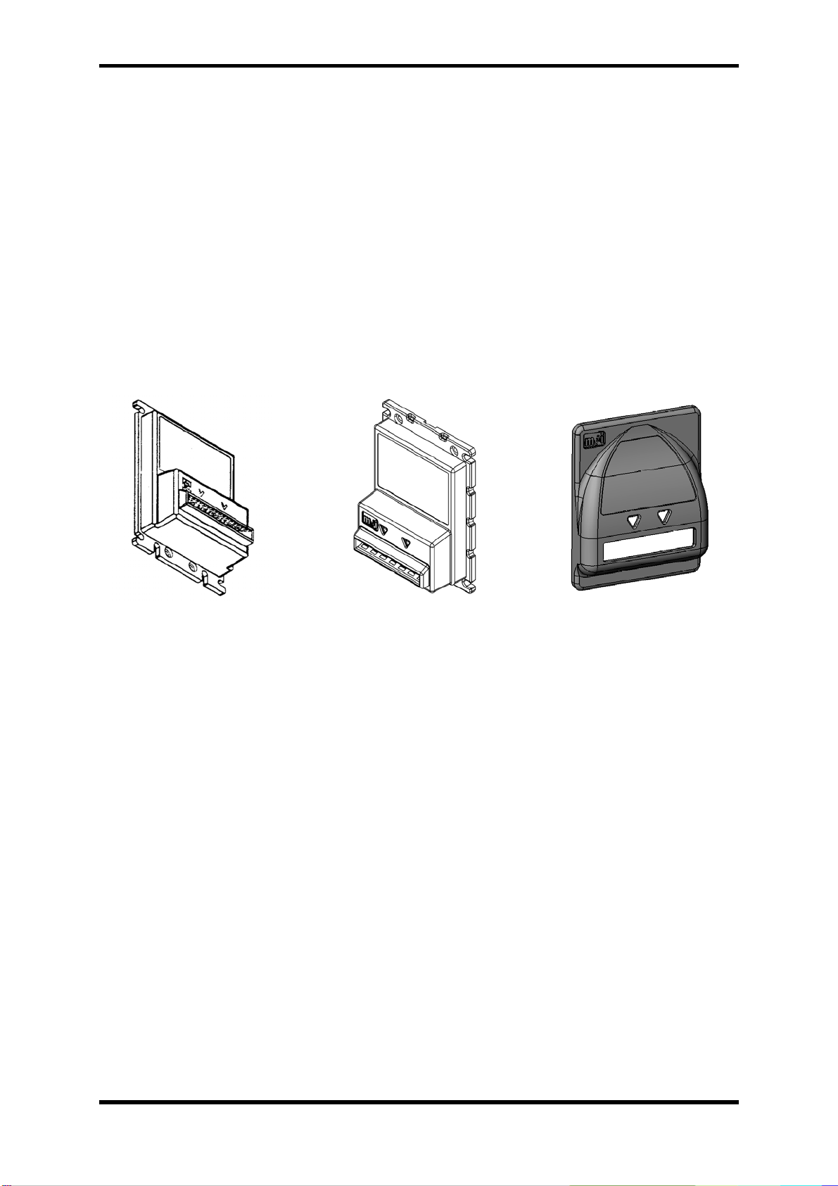
BEZELS ...............................................................................................................................................................8
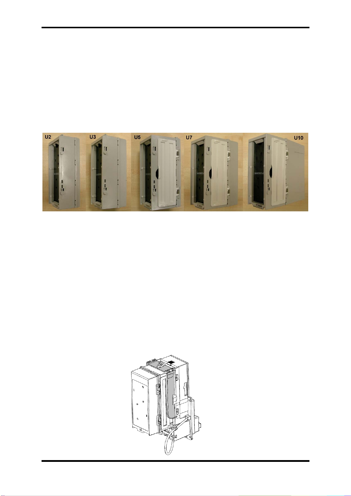
MAGAZINES ........................................................................................................................................................9
LOCKING HASP ...................................................................................................................................................9
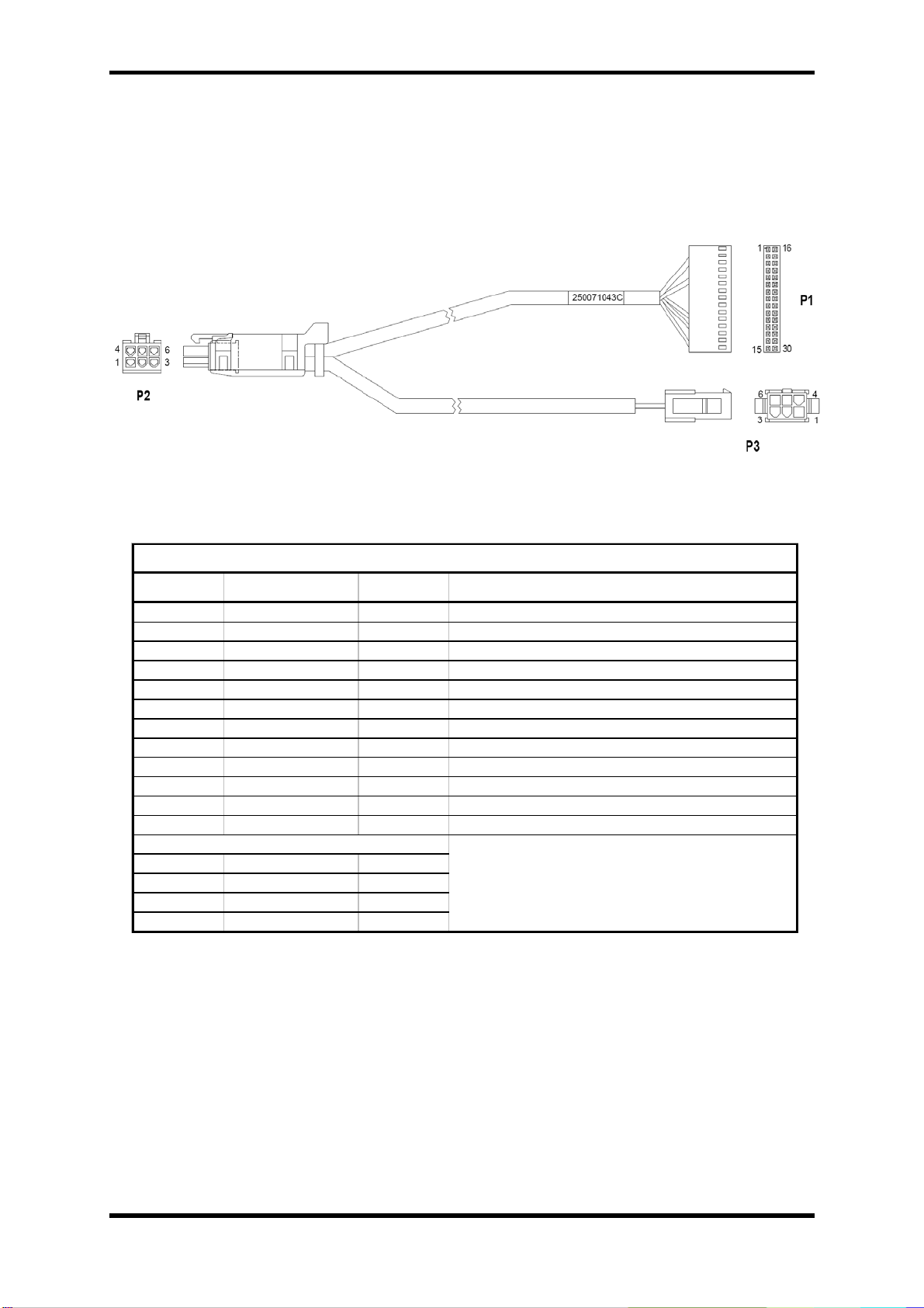
CABLES.............................................................................................................................................................10
INSTALLATION ...............................................................................................................................................13
UNPACKING THE NOTE ACCEPTOR....................................................................................................................13
MOUNTING THE NOTE ACCEPTOR.....................................................................................................................13
FIXING BRACKET ..............................................................................................................................................14
DIMENSIONS .....................................................................................................................................................15
CHANGER CONFIGURATION ..............................................................................................................................16
Highest Banknote Value............................................................................................................................................16
Software....................................................................................................................................................................16
Payout .......................................................................................................................................................................16
Testing.......................................................................................................................................................................16
WARRANTY ......................................................................................................................................................16
CONFIGURATION...........................................................................................................................................17
FACTORY CONFIGURATION...............................................................................................................................17
SWITCH SETTINGS.............................................................................................................................................18
Cashflow©2612 Switch Settings...............................................................................................................................19
Coupon Configuration...............................................................................................................................................23
OPERATION......................................................................................................................................................26
FUNCTIONAL OVERVIEW...................................................................................................................................26
INTERFACES ......................................................................................................................................................27
General......................................................................................................................................................................27
IHLP - Isolated High Level Pulse .............................................................................................................................27
ILLP - Isolated Low Level Pulse ..............................................................................................................................27
MDB - Multi-Drop Bus (24VAC units only)............................................................................................................27
MAINTENANCE ...............................................................................................................................................28
CLEANING.........................................................................................................................................................28
STATUS LED.....................................................................................................................................................29
EXPLODED VIEWS.............................................................................................................................................30
Chassis assembly.......................................................................................................................................................31
LED Housing Assembly............................................................................................................................................32
Sensor assembly........................................................................................................................................................33
Stacker/drive assembly..............................................................................................................................................34
Magazine Assembly..................................................................................................................................................35
Gearbox Assembly....................................................................................................................................................36

Cashflow
©2612 Engineers Handbook
©MEI 2009 Page 5 G1
GENERAL INFORMATION
Overview
The Cashflow©2612 Engineers Guide contains important information on installing, operating, and
maintaining MEI Note Acceptors. The Cashflow©2612 Note Acceptors take currency at high
acceptance rates and provide a superior level of resistance against specific cheats and frauds. To
obtain the best performance from your MEI Note Acceptor, read this manual and the Installation
Guide before installing and using the note acceptor.
Product Summary
The Cashflow©2612 is designed for vending applications in Europe. It offers enhanced security, and
one, two-way, and four-way acceptance of notes.
CASHFLOW©2612 Features
•Currently available for Euro, Russia and Saudi notes.
•1,2 and 4 way direction.
•Configuring available by option switches and coupon.
•MDB and Smart Serial Interface supported.
•Easy access to entire note path with unit installed in machine.
•High acceptance of currency.
•Returned or rejected notes held in note acceptor mouth until removed by customer.
•Choice of three different bezel styles
•Sealed optical sensors to enhance security and reduce effects of vandalism
•Status LED on back of unit to indicate current state of operation
•Designed for ease of maintenance
Power Specifications
•34 VDC at 2.0 amps (MDB mode)

Cashflow
©2612 Engineers Handbook
©MEI 2009 Page 6 G1
Model Number Explanation
Example:

Cashflow
©2612 Engineers Handbook
©MEI 2009 Page 7 G1
Serial Number Explanation
Example:
NOTE:
From week 09 2009 the number representing the Manufacture Location changed from an 8 to a 9.
This will allow the warranty serial number to continue into 2010 when the year code of 0 would be
duplicated with units already manufactured in 2000.
i.e. 0988 = manufactured in Week 9 2008
0999 = manufactured in Week 9 2009
0908 = manufactured in Week 9 2000
0909 = manufactured in Week 9 2010

Cashflow
©2612 Engineers Handbook
©MEI 2009 Page 8 G1
Bezels
The Cashflow©2612 offers three different bezel configurations: Compact, Armored, Anti-Vandal.
The Compact bezel allows for ease of note insertion with lighted arrows pointing to the place of
insertion.
The Armored bezel is a stainless steel version of the compact bezel.
The Anti-Vandal bezel is a caste iron bezel that fits over a compact bezel.
Bezel Kits
Bezel Kits are available to convert from one bezel style to another. Part numbers for the bezel
conversion kits are as follows:
Compact Bezel Kit Armored Bezel Kit Anti-Vandal Bezel Kit
Part Nos: Part No: Part No:
250063179 – Euro 250065178 – Euro 250063174
250066181 – Saudi
250068180 – Russia

Cashflow
©2612 Engineers Handbook
©MEI 2009 Page 9 G1
Magazines
Five different magazine sizes are available for the Cashflow©2612 note acceptors. Magazine
capacities of 200, 300, 500, 700 and 1000 notes are available.
•200,300 and 500 magazines are available on Euro Cashflow©2612.
•500 and 700 magazines are available on Saudi Cashflow©2612.
•500, 700 and 1000 magazines are available on Russia Cashflow©2612.
•The 200 and 300 magazine styles feature a hinged top door for note removal.
•The 500,700 and 1000 magazine styles use hinged side doors for note removal.
Euro Saudi Russia
200 Magazine (U2) - 250060184 - -
300 Magazine (U3) - 250068185 - -
500 Magazine (U5) - 250066186 250069017 250064187
700 Magazine (U7) - - 250068021 250062188
1000 Magazine (U10) - - - 250060189
Locking Hasp
A locking hasp kit is available that secures the side doors on the 500, 700 and 1000 note
magazines.

Cashflow
©2612 Engineers Handbook
©MEI 2009 Page 10 G1
Cables
MDB Cable
Part Number 250071043C
FROM WIRE COLOUR TO FUNCTION
P1-21 - N/C KEY
P1-23 WHITE P2-1 34V DC
P3-1 WHITE P2-1
P1-16 BROWN P2-2 DC RETURN
P3-2 BROWN P2-2
P1-6 BLACK P2-4 MDB MASTER RECEIVE
P3-4 BLACK P2-4
P1-14 RED P2-5 MDB MASTER TRANSMIT
P3-5 RED P2-5
P1-28 GREEN P2-6 MDB COMMON GND
P3-6 GREEN P2-6
P1-5 - N/C KEY
P1-2 - -
P1-17 - -
P1-15 - -
P1-30 - -
WIRE CHART
DUMMY TERMINALS IN THESE CAVITIES
TO ENHANCE CONNECTOR RETENTION

Cashflow
©2612 Engineers Handbook
©MEI 2009 Page 11 G1
Parallel Cable (24v AC)
Part Number 250077084C
FROM WIRE COLOUR TO FUNCTION
P1-3 RED P2-8 24v AC LIVE
P1-7 GREEN P3-8 CREDIT1
P1-10 BROWN P3-1 GROUND
P1-20 GREY P2-7 24V AC NEUTRAL
P1-24 ORANGE D1-1
D1-2 ORANGE P2-6
P1-25 PURPLE P3-9 CREDIT2
P1-5 - N/C KEY
P1-21 - N/C KEY
P3-7 - N/C KEY
WIRE CHART
INHIBIT 12V

Cashflow
©2612 Engineers Handbook
©MEI 2009 Page 12 G1
Parallel Cable (24v DC)
Part Number 250075085C
FROM WIRE COLOUR TO FUNCTION
P1-7 GREEN P2-5 CREDIT1
P1-9 GREY P2-8 BUSY
P1-16 BROWN P2-10 24v DC RETURN
P1-23 RED P2-9 24vDC
P1-24 ORANGE P2-3 ACCEPT ENABLE
P1-25 PURPLE P2-6 CREDIT2
P1-5 - N/C KEY
P1-21 - N/C KEY
P3-1 YELLOW P3-2 LINK
WIRE CHART

Cashflow
©2612 Engineers Handbook
©MEI 2009 Page 13 G1
INSTALLATION
Unpacking the Note Acceptor
Unpack the note acceptor and immediately inspect it for damage. If the unit is damaged, return it to its
original carton along with packing materials.
Notify the delivering carrier of damages and request immediate inspection. Send a letter of
intent to file a claim to the delivering carrier within 72 hours from the time of delivery. Send a
copy of the letter to the shipper.
Only the consignee (the person or company receiving the note acceptor) can file a claim against the
carrier for concealed damages.
Retain the original carton and packing materials for future use in shipping or transporting the
note acceptor.
Mounting the Note Acceptor
The Cashflow©2612 has been designed for ease of mounting onto existing studs provided
by Original Equipment Manufacturers (OEMs). Some machines may require brackets or
faceplates to mount the unit. Refer to your machine operation manual or contact your
distributor/OEM for more model-specific mounting information.
The Cashflow©2612 has a tie-wrap included with each unit to secure its interface harness to
the mounting area of the machine. Use the tie-wrap for every installation.
1. Disconnect all power to the machine.
2. Connect the interface harnesses from the
machine to the unit.
3. Wrap the tie-wrap around the interface harness.
5. Secure the unit to the mounting studs with the appropriate hardware.
(OEM Machine with fixing studs)

Cashflow
©2612 Engineers Handbook
©MEI 2009 Page 14 G1
(OEM Machine requiring bracket)
Fixing Bracket
Part Number 250067030
Kit Contains:
•Mounting Bracket
•6 x NUT, HEX #8-32, LOCKING

Cashflow
©2612 Engineers Handbook
©MEI 2009 Page 15 G1
Dimensions

Cashflow
©2612 Engineers Handbook
©MEI 2009 Page 16 G1
Changer Configuration
The majority of Note Acceptors are fitted to a Changers MDB Peripheral loom. It is advisable that
some options within the changer are adjusted when a Note Acceptor is fitted.
MDB Peripheral Loom
Highest Banknote Value
In the Service Mode Menu there is an option to set the highest value of Banknote. This is under
Banknote Configuration. It is normally set at €20.
Software
Since MEI software release V1.18 the behaviour of a Note Acceptor connected to the MDB
Peripheral loom is different. All the notes inserted will be held in escrow, which means not stacked
until the user makes a selection on the vending machine. Then the note will be stacked in the
magazine and the user will get the product and the change (in coins).
If the user inserts a note and presses the reject lever to get change, then the note will be returned.
This is to prevent users emptying the changer’s tubes without buying anything.
This option is only configurable with the STS tool.
Payout
If you are going to use a Note Acceptor it is recommended you change the payout of the Changer
adding one tube of €1 or €2 depending on the needs of the site. CF7000 has a wide range of pre-
programmed cassettes. Please contact your MEI technical support or local service center for further
information on this.
Testing
•Apply power to the machine.
•Check the Status LED for the "Steady ON" condition. If another condition exists, refer to the
Maintenance section for troubleshooting details.
•Insert a note to check acceptance. If enabled, the note should be accepted.
•Make a vend to ensure the proper credit is received and proper change is paid out for the note.
Warranty
All Cashflow©2612 Note Acceptors come with a Two Year Manufacturer’s Warranty. Once the unit
has been inspected, record the model and serial number from the label on the side of the note
acceptor. Refer to these numbers when you contact an MEI Approved Service Center for service or
information. The manufacturer’s warranty is based upon the date of manufacture. Parts and labour
are included in Warranty repairs.
The first four digits of the serial number contain the manufacturing date code (see Serial Number
Configuration section). This code indicates the beginning of the warranty period.

Cashflow
©2612 Engineers Handbook
©MEI 2009 Page 17 G1
CONFIGURATION
The Cashlow©2612 can be manually configured using a bank of eight option switches.
The Cashflow©2612 can also be configured using a configuration coupon.
Factory Configuration
The Cashflow©2612 Note Acceptor is factory configured with all switches in the OFF position.
The following configuration is programmed:
•Maximum directions for note acceptance (four-way)
•High acceptance
•€5; €10 Euro note enabled
•1 pulse per Euro
•MDB Interface
The unit will default to these selections whenever all option switches are OFF. Placing any
switch ON will override the factory settings and the note acceptor will operate according to the
switch settings you choose.
If the Cashflow©2612 is reprogrammed using a coupon with a different configuration, the new
configuration will be the default. If any option switch is turned ON, the option switch settings
will override the coupon setting. The coupon configuration will remain in memory.

Cashflow
©2612 Engineers Handbook
©MEI 2009 Page 18 G1
Switch Settings
The Cashflow©2612 allows configuration of interface options through option switch selection.
The option switches are located on the right-hand side of the note acceptor. The following pages
described how the option switches work for specific country variants.
Option Swiches

Cashflow
©2612 Engineers Handbook
©MEI 2009 Page 19 G1
Cashflow©2612 Switch Settings
Euro Cashflow©2612
Switches 1 and 2 Factory
Default
Switch 1 Switch 2
ON OFF 1 way note
acceptance
OFF ON 2 way note
acceptance
ON ON 4 way note
acceptance X
Switch 3 *
OFF High Acceptance X
ON High Security
Switch 4
ON Accept €5 notes X
OFF Reject €5 notes
Switch 5
ON Accept €10 notes X
OFF Reject €10 notes
Switch 6
Unassigned
Switches 7 and 8 **
Switch 7 Switch 8
ON OFF Short Pulse
OFF ON Long Pulse
ON ON Credit Line
OFF OFF Auto-Selected X
* Switch 3 affects all note denominations. See ‘Coupon
Configuration’ for individual acceptance/security enabling
options.
** Short Pulse - 30ms ON / 50ms OFF Timing
Long Pulse – 35ms ON / 300ms OFF Timing
Credit Line – single 150ms pulse
If you are connecting the unit to a Serial or MDB interface,
turn switches 7 and 8 OFF before connecting the harness.
Once power is applied, the unit will recognize the Serial or
MDB interface and will ignore switches 7 and 8.

Cashflow
©2612 Engineers Handbook
©MEI 2009 Page 20 G1
Russia Cashflow©2612
Switches 1 and 2 Factory
Default
Switch 1 Switch 2
ON OFF 1 way note
acceptance
OFF ON 2 way note
acceptance
ON ON 4 way note
acceptance X
Switch 3 *
OFF High Acceptance X
ON High Security
Switch 4
ON Accept 10Rb notes X
OFF Reject 10Rb notes
Switch 5
Unassigned
Switch 6
Unassigned
Switches 7 and 8 **
Switch 7 Switch 8
ON OFF Short Pulse
OFF ON Long Pulse
ON ON Credit Line
OFF OFF Auto-Selected X
* Switch 3 affects all note denominations. See ‘Coupon
Configuration’ for individual acceptance/security enabling
options.
** Short Pulse – 30ms ON / 50ms OFF Timing
Long Pulse – 35ms ON / 300ms OFF Timing
Credit Line – single 150ms pulse
If you are connecting the unit to a Serial or MDB interface,
turn switches 7 and 8 OFF before connecting the harness.
Once power is applied, the unit will recognize the Serial or
MDB interface and will ignore switches 7 and 8.
Table of contents
Other MEI Bank Note Validator manuals