MEI DSPpro Series User manual

-~
ARTISAN
®
~I
TECHNOLOGY
GROUP
Your definitive source
for
quality
pre-owned
equipment.
Artisan Technology
Group
Full-service,
independent
repair
center
with
experienced
engineers
and
technicians
on staff.
We
buy
your
excess,
underutilized,
and
idle
equipment
along
with
credit
for
buybacks
and
trade-ins
.
Custom
engineering
so
your
equipment
works
exactly as
you
specify.
•
Critical
and
expedited
services
•
Leasing
/
Rentals/
Demos
• In
stock/
Ready-to-ship
•
!TAR-certified
secure
asset
solutions
Expert
team
ITrust
guarantee
I
100%
satisfaction
All
tr
ademarks,
br
a
nd
names, a
nd
br
a
nd
s a
pp
earing here
in
are
th
e property of
th
e
ir
r
es
pecti
ve
ow
ner
s.
Find the Danaher / Kollmorgen / Motion Engineering DSPro-VME at our website: Click HERE

33 South La Patera Lane
Santa Barbara, CA 93117
ph (805) 681-3300
fax (805) 681-3311
www.motioneng.com
DSPpro Series
Motion Developer’s
User Manual
March 2002
Artisan Technology Group - Quality Instrumentation ... Guaranteed | (888) 88-SOURCE | www.artisantg.com

DSPpro Series
Motion Developer’s Manual
Mar 2002
Part # M001-0024 rev. B
Copyright 2002, Motion Engineering, Inc.
Motion Engineering, Inc.
33 South La Patera Lane
Santa Barbara, CA 93117-3214
ph 805-681-3300
fax 805-681-3311
e-mail: technical@motioneng.com
website: www.motioneng.com ftp site: ftp.motioneng.com
This document contains proprietary and confidential
information of Motion Engineering, Inc. and is
protected by Federal copyright law. The contents of
this document may not be disclosed to third parties,
translated, copied, or duplicated in any form, in
whole or in part, without the express written
permission of Motion Engineering, Inc.
The information contained in this document is subject
to change without notice. No part of this document may
be reproduced or transmitted in any form or by any
means, electronic or mechanical, for any purpose,
without the express written permission of Motion
Engineering, Inc.
All product names are trademarks or registered
trademarks of their respective owners.
Artisan Technology Group - Quality Instrumentation ... Guaranteed | (888) 88-SOURCE | www.artisantg.com

Table of Contents i
CONTENTS
INTRODUCTION 1
1.1 Troubleshooting & Technical Support ............................................................1
1.2 Quick Start ........................................................................................................2
1.3 Software Updates .............................................................................................2
1.4 A Note to OEMs.................................................................................................2
QUICK START 3
2.1 Installing DSPpro Controllers...........................................................................3
2.1.1 Hardware Installation ................................................................................................ 3
2.1.2 Software Installation.................................................................................................. 4
2.1.3 Connections & Wiring ............................................................................................... 4
2.2 Tuning your system and verifying basic operation.........................................5
DSPPRO CONTROLLER DESIGN 9
3.1 Architecture.......................................................................................................9
3.1.1 Program Storage .................................................................................................... 10
3.2 Firmware Execution.........................................................................................10
3.2.1 Read All Encoders ................................................................................................. 10
3.2.2 Read Analog and Parallel Input ............................................................................. 10
3.2.3 Calculate Next Trajectory Point ............................................................................. 10
3.2.4 Check for Event Triggers ....................................................................................... 11
3.2.5 Perform Event Actions ........................................................................................... 11
3.2.6 Calculate and Set DAC Output .............................................................................. 11
3.3 Hardware Features .........................................................................................12
3.3.1 Step Motor Control via VFCs ................................................................................. 12
3.3.2 Communication via three words in I/O Space........................................................ 12
HARDWARE INSTALLATION 14
4.0 Memory Addressing (DSPpro-VME) ...............................................................14
4.1 Installing the DSPpro-VME..............................................................................14
4.1.1 DSPpro-VME Dip Switch Locations........................................................................ 14
4.1.2 DSPpro-VME Base Memory Address Switch Settings ........................................... 15
4.1.3 DSPpro-VME Interrupt (IRQ) Switch Settings. ....................................................... 15
4.1.4 DSPpro-VME Board Installation Procedures .......................................................... 15
4.2 Installing the DSPpro-Serial............................................................................16
MEI SOFTWARE 17
Artisan Technology Group - Quality Instrumentation ... Guaranteed | (888) 88-SOURCE | www.artisantg.com

ii Table of Contents
5.1 The SETUP Program (DSETUP.EXE & SSETUP.EXE)....................................17
5.1.1 Overview................................................................................................................ 17
5.1.2 Using SETUP with the DSPpro............................................................................... 17
5.1.3 SETUP Screens..................................................................................................... 21
5.2 The VERSION Program (VERSION.EXE) ........................................................34
5.3 The CONFIG Program (CONFIG.EXE).............................................................35
MOTOR WIRING 37
6.1 Connection Accessories .................................................................................37
6.2 DSPpro-VME Motor Signal Header Locations ...............................................39
6.2.1 DSPpro-VME Motor Signal Pinouts (P4-P7)........................................................... 39
6.3 Motor Signal Header Locations - DSPpro-Serial ..........................................40
6.3.1 DSPpro-Serial Motor Signal Pinouts (P1-P4) ......................................................... 40
6.4 Wiring Servo Motors........................................................................................41
6.4.1 Velocity/Torque Mode............................................................................................. 41
6.4.2 Encoder Input ........................................................................................................ 41
6.4.3 Brush Servo Motors ............................................................................................... 41
6.4.4 Brushless Servo Motors......................................................................................... 43
6.4.5 Step-and-Direction Controlled Servo Motors ......................................................... 44
6.5 Wiring Step Motors..........................................................................................44
6.5.1 Open-Loop Step Motors ........................................................................................ 44
6.5.2 Direction Pulse Synchronization ............................................................................ 46
6.5.3 Closed-loop Step Motors ....................................................................................... 47
6.6 Wiring for Dual-Loop Control .........................................................................48
6.7 Interferometer Input Wiring (DSPpro-VME only) ..........................................48
6.7.1 Excel Precision 1000A Interferometer/Axis Board................................................. 49
6.7.2 Excel 1032B Interferometer Wiring Pin-Out Listing ............................................... 50
I/O WIRING 53
7.1 General ............................................................................................................53
7.2 I/O Wiring - DSPpro-VME.................................................................................53
7.3 I/O Wiring - DSPpro-Serial...............................................................................56
7.3.1 Dedicated I/O Wiring............................................................................................... 56
7.3.2 User I/O Wiring ....................................................................................................... 56
7.4 Home and limit switch wiring (DSPpro-VME only).......................................57
7.5 Dedicated and user output wiring .................................................................58
7.6 Opto-isolation .................................................................................................59
7.7 Analog input wiring ........................................................................................59
7.7.1 DSPpro-VME .......................................................................................................... 59
7.7.2 DSPpro-Serial ......................................................................................................... 59
7.8 8254 Counter wiring - DSPpro-VME.....................................................60
Artisan Technology Group - Quality Instrumentation ... Guaranteed | (888) 88-SOURCE | www.artisantg.com

Table of Contents iii
DEVELOPING YOUR APPLICATION 61
8.0 Overview ......................................................................................................61
8.1 Write the application program....................................................................62
8.2 Testing the Application Program ...............................................................62
8.2.1 Configuring Communications.................................................................................. 63
8.2.2 Using RCONSOLE to Test Your Application (DSPpro-PC only) ............................ 64
8.2.3 Using REMSVR to Test Your Application (DSPpro-VME or DSPpro-Serial).......... 65
8.2.4 Configure DOS startup files .............................................................................. 66
8.3 Committing your application to flash memory..........................................66
8.3.1 Committing your application to the DSPpro-VME or DSPpro-Serial....................... 67
APPENDIX A: CONNECTOR PINOUTS 68
A.1 DSPpro-VME Connector Layout.....................................................................68
A.2 Connector pinouts (DSPpro-VME) .............................................................68
A.3 DSPpro-Serial Connector Layout...................................................................71
A.4 DSPpro-Serial Connector Pinouts .................................................................71
APPENDIX B: SPECIFICATIONS 77
B.1 DSPpro-VME specifications ..........................................................................77
B.2 DSPpro-Serial specifications ........................................................................80
APPENDIX C: TUNING YOUR SYSTEM 83
C.1 General Description ........................................................................................83
C.1.1 The Digital Filter .................................................................................................... 83
C.2 Tuning Parameters.........................................................................................84
C.2.1 Proportional Gain (Kp )........................................................................................... 84
C.2.2 Derivative Gain (Kd ).............................................................................................. 85
C.2.3 Integral Gain (Ki )................................................................................................... 86
C.2.4 Velocity Feed Forward (Kv) .................................................................................. 87
C.2.5 Acceleration Feed-Forward (Ka ) ........................................................................... 88
C.2.6 Integration Limit..................................................................................................... 88
C.2.7 Offset (Ko)............................................................................................................. 88
C.2.8 Shift ....................................................................................................................... 88
C.2.9 Friction Feed Forward ........................................................................................... 89
C.3 Tuning Closed-Loop Servos..........................................................................89
C.3.1 Step 1: Set Proportional Gain (Kp )....................................................................... 89
C.3.2 Step 2: Set the Derivative Gain............................................................................. 89
C.3.3 Step 3: Iterate Steps 1 and 2 ................................................................................ 90
C.3.4 Step 4: Set Integral Gain (Ki ) ................................................................................ 90
C.3.5 Step 5: Set Velocity and Acceleration Feed Forward............................................ 90
C.4 Tuning Closed-Loop Steps............................................................................90
C.4.1 Step 1: Set Proportional Gain (Kp) ....................................................................... 91
C.4.2 Step 2: Set Velocity and Acceleration Feed Forward............................................ 91
Artisan Technology Group - Quality Instrumentation ... Guaranteed | (888) 88-SOURCE | www.artisantg.com

iv Table of Contents
C.4.3 Step 3: Setting the Integral Gain (Ki ) .................................................................... 91
INDEX 92
Artisan Technology Group - Quality Instrumentation ... Guaranteed | (888) 88-SOURCE | www.artisantg.com
Chapter 1: Introduction 1
Chapter 1
INTRODUCTION
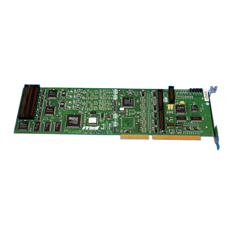
This manual describes how to install, wire, and use available development tools for MEI DSPpro
motion controllers. It is intended as a general reference guide for the DSPpro-Serial, DSPpro-PC
and DSPpro-VME and should be used in conjunction with the MEI DSP-Series Motion
Controller C Programming Manual, which documents the specific motion control functions
provided by the MEI standard C function library.
1.1 Troubleshooting & Technical Support
MEI takes technical support seriously. We want your system to work! Our staff of application
engineers are knowledgeable and dedicated to answering questions during the development of
your system. MEI provides technical support 24 hours a day free of charge for 5 years from the
date of your last purchase. Please feel free to call, fax, or e-mail us. We only ask that you take
the time to read the manuals and release notes to make sure that information has not been
overlooked.
Before calling Technical Support, make sure you know which product and what version of
software you are using. The software version is printed on the distribution disks and is displayed
in the SETUP program provided in the DOS, Windows 3.x, and Windows95 software support
disks. If you FAX or e-mail us your program (or code fragments) be sure to include specific
notes about where you are having problems. Also, don’t forget to include your phone and FAX
numbers and e-mail address.
The latest releases of software and firmware are available by anonymous FTP at our Internet site
at ftp://ftp.motioneng.com and on our 24 hour BBS at (805) 681-3313. No special
registration is necessary. The BBS supports baud rates up to 28.8 kbps, No Parity, 8 data bits, 1
stop bit. Files may be uploaded or downloaded. If you upload a file to our FTP site or BBS, be
sure to let us know by phone, FAX, or e-mail.
In addition, product information, recent press releases, and registration forms for MEI-sponsored
technical conferences can be found on our Web site at http://www.motioneng.com.
If you aren’t sure about how to begin developing your application, write down your questions
and/or a specification and FAX them to MEI at (805) 681-3311. We will answer your questions
and/or write a small sample program and FAX or e-mail them to you. We cannot write your
application code for you but we can save you development time by providing sample code.
Also, take a look at the Sample Applications distribution disk; it contains a variety of sample
programs that address common questions. This disk is constantly being updated with new
sample programs and creative solutions. The latest sample applications are available on our FTP
site and the BBS in a file called APPS.ZIP.
Artisan Technology Group - Quality Instrumentation ... Guaranteed | (888) 88-SOURCE | www.artisantg.com

2 Chapter 1: Introduction
Following is a list of our offices should you need to contact us.
Office Phone Fax E-mail BBS
West Coast 805-681-3300 805-681-3311 tech@motioneng.com 805-681-3313
East Coast 508-264-0051 508-264-0057
Midwest 773-631-4992 773-631-4935
1.2 Quick Start
For developers familiar with motion systems who want to get their motors turning as soon as
possible, we offer the “Quick Start” section. Also, to make it easy to test the hardware and tune
servo systems, a DOS-based SETUP program is provided with the DOS, Windows 3.x, and
Windows 95 software support disks. The SETUP program is designed to be self-explanatory for
experienced developers who prefer to explore and learn on-the-fly.
1.3 Software Updates
MEI periodically releases new software/firmware versions. New features are implemented,
performance enhanced and new applications developed. The latest firmware and software
releases are available on our FTP site at ftp://ftp.motioneng.com as well as the MEI
BBS.
1.4 A Note to OEMs
MEI always ships DSPpro controllers with the latest firmware. When building multiple
machines we strongly recommend that you save a configured version of your firmware to a disk.
Then, the next time you build a machine simply load that firmware (from disk) to the DSPpro
controller using the CONFIG program. This method will give you the greatest control and ease
in building future machines.
Artisan Technology Group - Quality Instrumentation ... Guaranteed | (888) 88-SOURCE | www.artisantg.com

Chapter 2: Quick Start 3
Chapter 2
QUICK START
This chapter offers a fast and easy installation procedure for those already familiar with MEI
controllers, software libraries, and motion controller connections. For more information on MEI
software libraries, please refer to the MEI DSP-Series Motion Controller C Programming
Manual. Those unfamiliar with wiring controllers should see the “Hardware Installation” and
“Motor Wiring” sections of this manual for wiring diagrams and a detailed discussion of
installation procedures.
Depending on your operating system and configuration, you may be able to use one or more
included DOS-based utilities to help you tune your system and verify initial operation. For more
information, refer to section 2.2, “Tuning your system and verifying basic operation.”
2.1 Installing DSPpro Controllers
2.1.1 Hardware Installation
DSPpro-PC
The DSPpro-PC is a board-level controller designed for PC compatible (ISA bus) computers.
1. Open the shipping container and carefully remove its contents. Be sure to observe proper
ESD handling precautions.
2. Turn off the host computer.
3. Select an available ISA expansion slot and remove its expansion cover plate.
4. The default memory location of the DSPpro-PC is 0xD000:0000. If you need to change this,
refer to section 4.1, “Installing the DSPpro-PC.”
5. Remove the anti-static protective cover from the DSPpro-PC bus connectors.
6. Insert the DSPpro-PC in the ISA bus connector and secure the card in place with the screw
from the cover plate.
For detailed hardware installation instructions, please see section 4.1.
DSPpro-VME
The DSPpro-VME is a single, 6U slot, board-level controller designed for VME-based
computers.
1. Open the shipping container and carefully remove its contents. Be sure to observe proper
ESD handling precautions.
2. Turn off the host computer.
Artisan Technology Group - Quality Instrumentation ... Guaranteed | (888) 88-SOURCE | www.artisantg.com

4 Chapter 2: Quick Start
3. Select an available VME expansion slot and remove its expansion cover plate.
4. The default memory location of the DSPpro-VME is 0xFFFF0300. If you need to change
this, refer to section 4.2, “Installing the DSPpro-VME.”
5. Insert the DSPpro-VME in the VME bus and firmly press the card into place until the card
is properly seated and locked into place.
6. Connect the Console port on the DSPpro-VME to a serial port (e.g. COM1) of the host
computer using a null modem cable (available from MEI as accessory cable CBL-D9
CONSOLE).
For detailed hardware installation instructions, please see section 4.2.
DSPpro-Serial
The DSPpro-Serial is a standalone controller that communicates with a host computer using an
RS-232 serial port. The following instructions describe how to setup the DSPpro-Serial for
application development. After application development, the DSPpro-Serial can operate
independent of the host computer.
1. Open the shipping container and carefully remove its contents.
2. Turn off the host computer.
3. Connect the Console port on the DSPpro-Serial to a serial port (e.g. COM1) of the host
computer using a null modem cable (available from MEI as accessory cable CBL-D9
CONSOLE).
4. Connect your 24 VDC power lines to the screw-terminal connector which plugs in to the
power port of the DSPpro-Serial. Be sure to observe proper polarity.
For detailed hardware installation instructions, please see section 4.3, “Installing the DSPpro-
Serial.”
2.1.2 Software Installation
DSPpro motion controllers are available with software support packages for many popular
operating systems including DOS, Windows 3.x, Windows95, and Windows NT. Limited
support for other development environments is also available. Contact your MEI representative
for more information.
Refer to the release notes which accompany your software support package for information on
installing the software distribution.
2.1.3 Connections & Wiring
After installing the controller and software, you are ready to wire your system. Since your
specific configuration may vary, below are general guidelines for wiring your system. Before
beginning, make sure all drives are turned off.
1. Connect drives to motors (consult your drive documentation for connection details).
2. Connect the DSPpro to the drive.
Artisan Technology Group - Quality Instrumentation ... Guaranteed | (888) 88-SOURCE | www.artisantg.com

Chapter 2: Quick Start 5
3. Connect the encoders to the DSPpro.
4. Connect power cable to controller (DSPpro-Serial only).
For detailed connections and wiring instructions, please see chapter 6, “Motor Wiring,” and
chapter 7, “I/O Wiring.”
2.2 Tuning your system and verifying basic
operation
If you are using a PC running DOS, Windows 3.x, or Windows 95 or can run DOS applications
using another type of computer, you can use MEI’s SETUP program to tune your motion system
and to verify basic controller operation. From within this application, you can modify tuning,
generate point to point motion, and test various other aspects of the controller.
Before following these instructions, be sure to properly wire your system as described in chapter
6, “Motor Wiring,” and chapter 7, “I/O Wiring.”
Verifying Operation - Servos
Follow these instructions if your application uses SERVO motors.
1. From the factory, the DSPpro is configured to connect to the SETUP program running on the
host PC. If you have not modified the DSPpro flash memory, skip to step 6.
2. Insert the disk labeled DSPpro Quick Start Disk into the floppy disk drive of your PC.
3. If you are using the DSPpro-Serial or DSPpro-VME, execute the program by typing
REMSVR from a DOS prompt on your host PC. If the DSPpro console cable is connected to
COM2 of your PC, execute REMSVR by typing REMSVR /2. You will see the following
output in the REMSVR window of your PC:
Motion Engineering Console/Disk Server V1.0
Copyright (C) 1996 Motion Engineering, Inc.
Press Alt-X to exit
Connecting Through COM1
Reset the controller by depressing the reset button. Use a paper-clip to reach the recessed reset
button on the DSPpro-Serial.
If you are using the DSPpro-PC, execute the RCONSOLE program by typing RCONSOLE /r
from a DOS prompt on your host PC. The /r switch reboots the controller before starting
RCONSOLE. You will see the following output in the RCONSOLE window of your PC:
RCONSOLE v1.0 (c) 1996 Motion Engineering, Inc.
4. The DSPpro will then reboot, booting from the DSPpro Quick Start Disk in the floppy drive
of your host PC. You will see the following output in the REMSVR or RCONSOLE window
of your PC:
Motion Engineering 80C386EX BIOS V1.0
Copyright (C) 1992-1995 Motion Engineering, Inc.
Copyright (C) 1992-1995 General Software, Inc.
00896 KB OK
Artisan Technology Group - Quality Instrumentation ... Guaranteed | (888) 88-SOURCE | www.artisantg.com

6 Chapter 2: Quick Start
Embedded BIOS ROM Disk Enabled
Embedded BIOS REMOTE Disk [COM1] [CONNECTED]
Starting MS-DOS…
Server 1.00A Oct 11 1996 14:10:40
Listening on COM1.
5. Exit from RCONSOLE or REMSVR by typing ALT-X.
6. Execute the SETUP program by typing ssetup from a DOS prompt on your host PC if you
are connecting to a DSPpro-VME or DSPpro-Serial, or dsetup if you are connecting to a
DSPpro-PC. Note that if you are connecting to a DSPpro-VME or DSPpro-Serial using
COM2 of your host PC, type ssetup /2 to tell the SETUP program to connect through
COM2.
7. Configure Axis 0 of the controller as a servo axis, closed loop, bipolar with the
Configure/Axis Configuration window (Shortcut key F8).
8. Put the axis in Idle mode using the Status/Axis Status (F3) window.
9. Turn on the amplifier.
10. Test the encoder connections with the Status/Position Status (F2) window - turn the motor
and verify it gives the correct number of encoder counts.
11. Apply an initial constant voltage of 100 using the offset register in the Configuration/Tuning
Parameters (F7) window. Check to see that positive offsets produce increasing position
value. If not, swap the A+ and B+ encoder leads, and swap the A- and B- encoder leads.
12. Clear the position with the Status/Position Status (F2) window.
13. Put the axis in Run mode with the Status/Axis Status (F3) window. The motor should now be
servoed.
Verifying Operation - Steppers
Follow these instructions if your application uses STEP motors.
1. From the factory, the DSPpro is configured to connect to the SETUP program running on the
host PC. If you have not modified the DSPpro flash memory, skip to step 6.
2. Insert the disk labeled DSPpro Quick Start Disk into the floppy disk drive of your PC.
3. If you are using the DSPpro-Serial or DSPpro-VME, execute the REMSVR program by
typing REMSVR from a DOS prompt of you host PC. If the DSPpro console cable is
connected to COM2 of your PC, execute REMSVR by typing REMSVR /2. You will see
the following output in the REMSVR window of your PC:
Motion Engineering Console/Disk Server V1.0
Copyright (C) 1996 Motion Engineering, Inc.
Press Alt-X to exit
Connecting Through COM1
Reset the controller by depressing the reset button. Use a paper-clip to reach the recessed reset
button on the DSPpro-Serial.
Artisan Technology Group - Quality Instrumentation ... Guaranteed | (888) 88-SOURCE | www.artisantg.com

Chapter 2: Quick Start 7
If you are using the DSPpro-PC, execute the RCONSOLE program by typing RCONSOLE /r
at a DOS prompt. The /r switch reboots the controller before starting RCONSOLE. You
will see the following output in the RCONSOLE window of your PC:
RCONSOLE v1.0 (c) 1996 Motion Engineering, Inc.
4. The DSPpro will then reboot, booting from the DSPpro Quick Start Disk in the floppy drive
of your host PC. You will see the following output in the REMSVR or RCONSOLE window
of your PC:
Motion Engineering 80C386EX BIOS V1.0
Copyright (C) 1992-1995 Motion Engineering, Inc.
Copyright (C) 1992-1995 General Software, Inc.
00896 KB OK
Embedded BIOS ROM Disk Enabled
Embedded BIOS REMOTE Disk [COM1] [CONNECTED]
Starting MS-DOS…
Server 1.00A Oct 11 1996 14:10:40
Listening on COM1.
5. Exit from RCONSOLE or REMSVR by typing ALT-X.
6. Execute the SETUP program by typing ssetup from a DOS prompt on your host PC if you
are connecting to a DSPpro-VME or DSPpro-Serial, or dsetup if you are connecting to a
DSPpro-PC. Note that if you are connecting to a DSPpro-VME or DSPpro-Serial using
COM2 of your host PC, type ssetup /2 to tell the SETUP program to connect through
COM2.
7. Configure Axis 0 as a step axis, open loop, unipolar with the Configure/Axis Configuration
(F8) window.
8. Put the axis in Idle mode using the Status/Axis Status (F3) window.
9. Apply a constant pulse rate using the offset register in the Configuration/Tuning Parameters
(F7) window. Note that only positive offset values will produce rotation.
10. Clear the position with the Status/Position Status (F2) window.
Artisan Technology Group - Quality Instrumentation ... Guaranteed | (888) 88-SOURCE | www.artisantg.com

8 Chapter 2: Quick Start
11. Put the axis in Run mode with the Status/Axis Status (F3) window.
12. Command a trapezoidal motion using the Motion/Two-Point Motion Window.
13. Verify that the motor turns one rotation when the appropriate number of steps are
commanded.
Artisan Technology Group - Quality Instrumentation ... Guaranteed | (888) 88-SOURCE | www.artisantg.com

Chapter 3: DSPpro Controller Design 9
Chapter 3
DSPpro CONTROLLER DESIGN
3.1 Architecture
The DSPpro design combines an Intel 386EX microprocessor with an Analog Devices DSP.
High-level decisions and communications with the host processor occur on the 386EX, while the
DSP is responsible for numerically intensive calculations.
Board-level DSPpro series controllers are mapped into the memory space of the host CPU, which
allows fast, direct binary communication across the data bus.
Figure 3-1. DSPpro architecture - dual-processor motion control
For maximum design flexibility, motion control programs can be created on a standard PC, using
off-the-shelf C programming tools (Microsoft, Borland, etc.). Compiled programs can be
downloaded to the DSPpro and stored in on-board flash memory.
With embedded DOS running on the Intel 386EX, standard programs can execute on the DSPpro,
completely independent of the host processor.
The DSP section of the controller uses an Analog Devices 40MHz DSP for real-time
calculations. The DSP handles all servo loop calculations, command position trajectory
calculations, frame buffer execution, response to programmable software limits, hardware limits,
plus many other functions.
A complete function library with source code is provided with the DSPpro controller. The
library functions manipulate and conceal the internal details of the controller, allowing the
programmer to concentrate on the application.
Artisan Technology Group - Quality Instrumentation ... Guaranteed | (888) 88-SOURCE | www.artisantg.com

10 Chapter 3: DSPpro Controller Design
3.1.1 Program Storage
DSPpro controllers offer 1 Mbyte of DRAM and 1 Mbyte of non-volatile flash memory to store
multiple motion control programs for execution as needed.
3.2 Firmware Execution
After the firmware is loaded, the DSP constantly executes the following series:
Read All Encoders
Calculate Next
Tra
j
ector
y
Point
Check for
Event Tri
gg
ers
Perform Event
A
ction
Calculate and
Set DAC Out
p
ut
Next Axis?
DSP Timer Interrupt
Exit From Interrupt
Read Analog
and Parallel In
p
ut
Figure 3-2. Main Loop
3.2.1 Read All Encoders
Immediately after the DSP’s timer interrupt (time interval is determined by the sample rate), the
DSP reads all eight encoder inputs and stores them into memory for future use. Then the DSP
runs a series of events for each axis before the next timer interrupt.
3.2.2 Read Analog and Parallel Input
If an axis is configured to read an analog input, the DSP writes a control word to the A/D, waits
for the conversion, reads the 12-bit digital value, and stores its value in memory. If an axis is
configured to read the parallel input, the DSP reads the 32 user I/O bits and stores its value in
memory.
3.2.3 Calculate Next Trajectory Point
The DSP calculates an axis’ command position trajectory. It maintains a command jerk,
command acceleration, command velocity, and command position:
Tn = Tn-1 + FS Tn is the time at sample n
An = An-1 + FS * J J is the jerk
Artisan Technology Group - Quality Instrumentation ... Guaranteed | (888) 88-SOURCE | www.artisantg.com

Chapter 3: DSPpro Controller Design 11
Vn = Vn-1 + FS * An An is the acceleration at sample n
Xn = Xn-1 + FS * Vn Vn is the velocity at sample n
Xn is the command position at sample n
FS is the feed speed
The command velocity is the rate of change of the command position, acceleration is the rate of
change of the command velocity, and jerk is the rate of change of the command acceleration.
3.2.4 Check for Event Triggers
The DSP checks an axis’ positive limit input, negative limit input, home input, amp fault input,
and software position limits. Also, the DSP checks the axis for time limits, position triggers, and
I/O triggers to determine if a new frame is to be executed.
3.2.5 Perform Event Actions
If an event trigger exists for an axis, the DSP performs the associated event. The possible events
are: Abort Event (highest priority), E-Stop Event, Stop Event, or New Frame Event (lowest
priority).
3.2.6 Calculate and Set DAC Output
The DSP calculates an axis’ output (analog voltage or pulse rate) based on a PID servo control
algorithm. The input to the PID algorithm is the current position error. The current position
error equals the difference between the command position and the actual position. The actual
position is controlled by the feedback device, and command position is controlled by the
trajectory calculator. The PID algorithm is based on the following formula:
On = KR( Kp*En + Kd*(En - En-1) + Ki*Sn + Kv*Vn + 64*Ka*An + Kf * Mn) + Ko
The subscripted n represents the sample period. The terms are defined:
Sn = Sn-1 + En if -Smax < Sn < Smax
Smax if Sn > Smax
-Smax if Sn < -Smax
On = DAC output KR= overall scale factor
Kp = proportional gain Kd = derivative gain
Ki = integral gain Kv = velocity feed-forward
Ka = acceleration feed-forward Ko = static DAC offset
Kf = friction feed-forward En = position error
Mn = 0 or 1 based on the command velocity Vn = command velocity
An = command acceleration Sn = integrated error
Smax = maximum integrated error
Artisan Technology Group - Quality Instrumentation ... Guaranteed | (888) 88-SOURCE | www.artisantg.com

12 Chapter 3: DSPpro Controller Design
The error (En) is the basis for changes in control voltage (On). To review how each element of
the PID algorithm affects motion, refer to appendix C, “Tuning Your System.” The same PID
algorithm is used for open-loop and closed-loop servo and step motor control. This feature makes
the programming the same for both motor types.
3.3 Hardware Features
3.3.1 Step Motor Control via VFCs
Step motors are controlled via the analog control voltage. The analog control voltage (DAC) is
connected to a voltage to frequency converter (VFC). The VFC generates a pulse train directly
proportional to the input voltage. The relationship between the analog control voltage and the
pulse output rate is constant and linear over the entire frequency range.
This is a major performance enhancement over timer/divider pulse generators that have
exponential pulse output rates and will cause large changes in step rate at high frequencies.
Since a step motor's torque curve is inversely related to its speed, it is more susceptible to stalling
at high speeds. Thus, a VFC at high pulse rates is less likely to stall a step motor. Another
advantage of the VFC is the high pulse output resolution.
The step pulse output supports the following speed ranges:
Slow 0 to 23 kHz
Medium 0 to 94 kHz
Fast 0 to 375 kHz
The voltage level at which steps are produced by the VFCs is determined by the internal DAC
offset set by the CONFIG program. This offset is usually required so that the DAC’s output zero
agrees with the VFC’s input zero. If the analog zero volt output is above the VFC zero input, the
VFC will begin to output step pulses.
The firmware guarantees the VFC will not output steps when command velocity is zero and the
position error is zero. If the offset is set too high, the firmware will automatically “shut down”
the step pulse output at the end of a move. If the offset was set too low, a small delay would
occur between the time the command position changes and the step motor actually starts moving.
The delay would be minimal, rarely exceeding two sample periods and would be based on the
acceleration and velocity figures.
One great design advantage to using VFCs based on servo DAC outputs is the same
programming is used to control either step or servo motors. If no motors are connected to the
DSPpro-Series controller, you can simulate motors by configuring the axes as open-loop
steppers.
3.3.2 Communication via three words in I/O Space
On a hardware level, the controller is a small microcomputer unto itself. It has its own address
and data bus that the DSP, its data memory, and peripherals (dedicated and non-dedicated I/O,
analog inputs and outputs, encoder inputs, and timer) use for communication. The 386EX has
Artisan Technology Group - Quality Instrumentation ... Guaranteed | (888) 88-SOURCE | www.artisantg.com

Chapter 3: DSPpro Controller Design 13
access to the address and data busses of the DSP controller through three words in its I/O space.
The 386EX and the DSP do not communicate directly. Instead, messages are passed through the
DSP's external data memory. It is like a chalkboard, where we communicate by reading or
writing messages, instead of directly modifying DSP registers.
External data memory is mostly dedicated to the frame buffer containing information about
changes in an axis' current trajectory. For example, a constant velocity move will have an
acceleration frame, followed by a slowing or constant velocity frame. These two frames are
downloaded into the buffer for DSP execution.
The library's job is to simplify this interface. While we gain immense flexibility in axis trajectory
manipulation, most applications only require simple trapezoidal-profile or similar motion.
Rather than being concerned with the low-level details of frames, the programmer need only be
concerned with library functions controlling trapezoidal profile or any other type of motion.
These functions translate trapezoidal or other motion profiles into frames for you.
Artisan Technology Group - Quality Instrumentation ... Guaranteed | (888) 88-SOURCE | www.artisantg.com
This manual suits for next models
1
Table of contents
Other MEI Controllers manuals
Popular Controllers manuals by other brands

Nordson
Nordson Spectra 30 product manual

Russound
Russound ALTX SC instruction manual

UHPPOTE
UHPPOTE HBK-A01 user manual

CIMCON Lighting
CIMCON Lighting iSLC3100-7P-N Installation and Commissioning Procedure

Johnson Controls
Johnson Controls EDA-8000 Installation sheet

National Instruments
National Instruments GPIB-VXI/C user manual