SPERONI LC 1800 DC User manual

Gasoline Generator
Generatori a Benzina
Instruction manual
Libretto Istruzioni

CONTENTS
1. SAFETY........................................................................................................................................................................................................................................5
1) Safety Label Locations......................................................................................................................................................................................5
2) Safety Information ..................................................................................................................................................................................................6
2. COMPONENT IDENTIFICATION..................................................................................................................................................................8
3. CONTROLS.........................................................................................................................................................................................................................10
1) Engine Switch............................................................................................................................................................................................................10
2) Recoil Starter..............................................................................................................................................................................................................10
3) Fuel Valve........................................................................................................................................................................................................................10
4) Choke .................................................................................................................................................................................................................................11
5) Circuit Breaker ........................................................................................................................................................................................................12
6) Ground Terminal ...................................................................................................................................................................................................12
7) Oil Alert System .....................................................................................................................................................................................................12
4. GENERATOR USE ....................................................................................................................................................................................................13
1) Connections to a Building’s Electrical System................................................................................................................13
2) Ground System........................................................................................................................................................................................................13
3) AC Applications .....................................................................................................................................................................................................14
4) AC Operation..............................................................................................................................................................................................................15
5) DC Operation.............................................................................................................................................................................................................15
6) High Altitude Operation.................................................................................................................................................................................17
5. PREOPERATION CHECK..................................................................................................................................................................................17
1) Engine Oil........................................................................................................................................................................................................................18
2) Fuel.........................................................................................................................................................................................................................................19
6. STARTING/STOPPING THE ENGINE............................................................................................................................................... 21
7. MAINTENANCE............................................................................................................................................................................................................ 22
1) Maintenance Schedule................................................................................................................................................................................. 22
2) Tool Kit ............................................................................................................................................................................................................................ 23
3) Engine Oil Change.............................................................................................................................................................................................. 23
4) Air Cleaner Service............................................................................................................................................................................................. 24
5) Fuel Sediment Cup............................................................................................................................................................................................ 25
6) Spark plug ................................................................................................................................................................................................................... 25
7) Spark Arrester Maintenance ................................................................................................................................................................. 27
8. TRANSPORTING/STOREGE ....................................................................................................................................................................... 29
9. TROUBLESHOTTING ........................................................................................................................................................................................... 31
10. WIRING DIAGRAM .................................................................................................................................................................................................. 32
11. SPECIFICATIONS ..................................................................................................................................................................................................... 35
12. OPTIONAL PARTS ................................................................................................................................................................................................... 37
2
CONTENTS
GB

INDICE
1. SICUREZZA ....................................................................................................................................................................................... 40
1) ) Posizione delle targhette disicurezza ................................................................................................................. 40
2) Informazioni per la sicurezza........................................................................................................................................ 41
2. IDENTIFICAZIONE DEI COMPONENTI ....................................................................................................................... 43
3. COMANDI ............................................................................................................................................................................................. 45
1) Interruttore del motore......................................................................................................................................................... 45
2) Motorino di avviamento a corda ................................................................................................................................. 45
3) Valvola del carburante ......................................................................................................................................................... 45
4) Valvola dell’aria ......................................................................................................................................................................... 46
5) Interruttore salvavita ............................................................................................................................................................. 47
6) Morsetto di messa a terra ............................................................................................................................................... 47
7) Sistema di controllo dell’olio .......................................................................................................................................... 47
4. USO DEL GENERATORE ....................................................................................................................................................... 48
1) Collegamenti al sistema elettrico di un edificio ............................................................................................ 48
2) Sistema di messa a terra .................................................................................................................................................. 48
3) Apparecchi a corrente alternata AC......................................................................................................................... 49
4) Funzionamento con corrente alternata AC........................................................................................................ 50
5) Funzionamento con corrente diretta DC.............................................................................................................. 50
6) Funzionamento a quote elevate .................................................................................................................................. 52
5. CONTROLLO PREOPERATIVO ......................................................................................................................................... 53
1) Olio del motore ......................................................................................................................................................................... 53
2) Carburante..................................................................................................................................................................................... 54
6. ACCENSIONE/SPEGNIMENTO DEL MOTORE................................................................................................... 56
7. MANUTENZIONE .......................................................................................................................................................................... 57
1) Tabella di manutenzione.................................................................................................................................................... 57
2) Kit di attrezzi ............................................................................................................................................................................... 58
3) Cambio dell’olio del motore .......................................................................................................................................... 59
4) Manutenzione del filtro dell’aria ................................................................................................................................. 59
5) Pulizia della vasca di sedimentazione del carburante.............................................................................. 60
6) Manutenzione delle candele........................................................................................................................................... 60
7) Manutenzione del parascintille..................................................................................................................................... 62
8. TRASPORTO/CUSTODIA ...................................................................................................................................................... 64
9. INDIVIDUAZIONE ED ELIMINAZIONE DI GUASTI ........................................................................................... 66
10. SCHEMA DEL CABLAGGIO ................................................................................................................................................ 67
11. SPECIFICHE ...................................................................................................................................................................................... 70
12. COMPONENTI FACOLTATIVI ............................................................................................................................................ 72
INDICE
I
3

Thank you for purchasing our generator. We want to help you get the best results from
your new generator and to operate it safety.
This manual contains the information on how to do that; please read it carefully.
All information and specifications in this publication is based on the lastest product
information available at the time of printing.
DC type is equipped for DC outlet. DDC type is equipped for both eletric starting and
DC outlet.
This manual should be considered a permanent part of the generator and should
remain with it if is resold.
Safety Messages
Your safety and the safety of others are very important. We have provided important
safety messages in this manual and on the generator. Please read these messages
carefully.
A safety message alerts you to potential hazard that could hurt your or others. Each
safety message is proceded by a safety alert symbols and one of tree words:
DANGER, WARNING, or CAUTION. These mean:
Damage Prevention Messages
Other important messages are preceded by the word NOTICE. this word means:
The purpose of these messages is to help prevent damage to your generator, other
property, or the environment.
DANGER
WARNING
CAUTION
You WILL be KILLED or SERIOUSLY HURT if you don’t
follow instructions.
You CAN be KILLED or SERIOUSLY HURT if you don’t
follow instructions.
You can be HURT if you don’t follow instructions.
NOTICE Your generator or other property could be damaged if you
don’t follow instructions.
GB
4
1. SAFETY
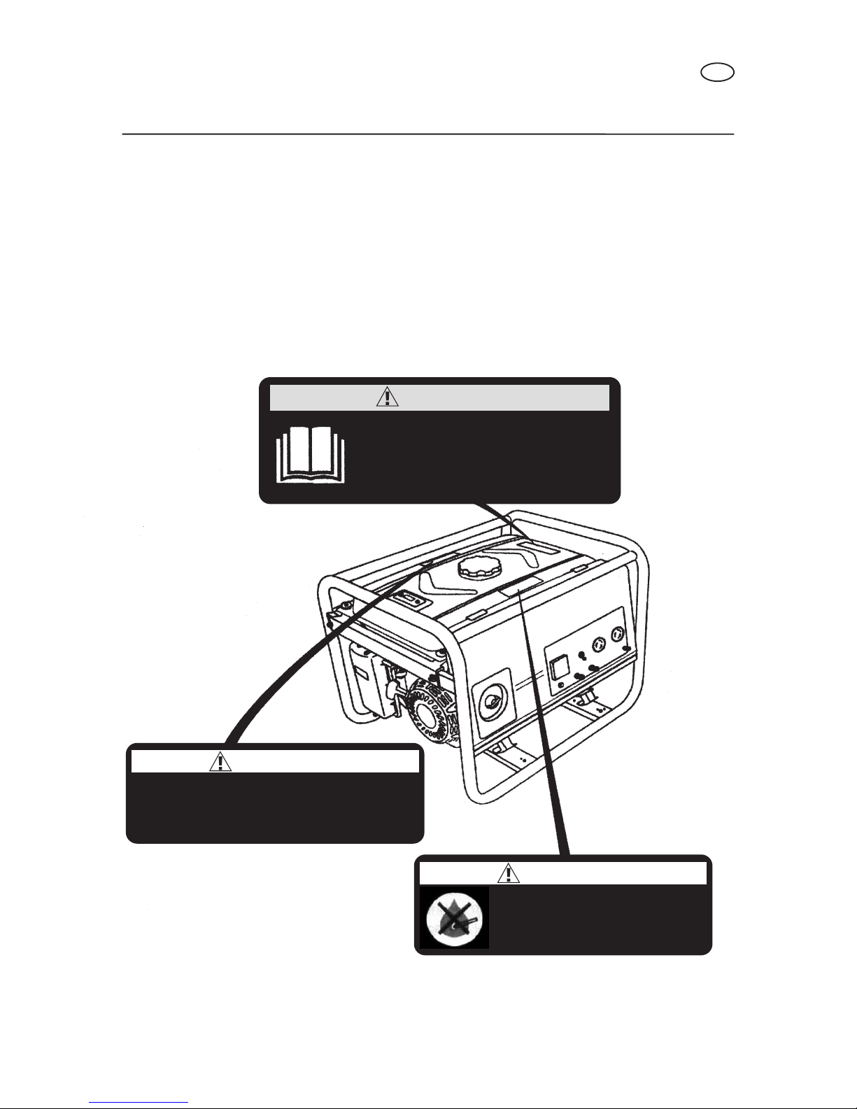
1) SAFETY LABEL LOCATION
These labels warn you of potential hazards that can cause serious injury. Read them
carefully.
If a label comes off or becomes hard to read, contact your generator dealer for a
replacement.
SAFETY
WARNING
Check that there is no any
fuel spilling or fuel leakage.
Filling fuel before stalling the
engine is forbidden.
Among engine exhaust emissions, there toxic
CO.so never use in an enclosed room without
good ventilation.
WARNING
Before operation, be sure to add specified
engine oil into the crankcase. Please refer
to the OWNER’S MANUAL for further
information
CAUTION
ST
GB
5

2) SAFETY INFORMATION
Our generator are designed to give safe and dependeble service if operated acording
to instructions. Read and understand this owner’s manual before operating your generator.
You can help prevent accidents by being familiar with your generator’s controls, and by
observing safe operating procedures.
Operator Responsability
• Know how to stop the generator quickly in case of emergency.
• Understand the use of all generator controls, output receptacles, and connections.
• Be sure that anyone who operates the generator receives proper instruction. Do not
let children operate the generator without parental supervision. Keep children and
pets away from the area of operation.
• Place the generator on a firm, level surface and avoid loose sand or snow. If the
generator is tilted or overturned, fuel spillage may result. Also, if the generator is
overturned or sinks into a soft surface, sand, dirt, or water may enter the generator.
SAFETY
CAUTION
HIGH TEMPERATURE PART! DONT TOUCH IT!
MUFFLER! HOT!
GB
6

Carbon Monoxide Hazards
• Exhaust contains poisonous carbon monoxide, a colorless and odorless gas.
Breating exhaust can cause loss of consciousness and may lead to death.
• If you run the generator in an area that is confined, or even partially enclosed, the air
you breathe could contain a dangerous amount of exhaust gas. To keep exhaust gas
from building up, provide adequate ventilation.
Eletric Shock Hazards
• The generator produces enough eletric power to cause a serious shock or
electrocution if misuded.
• Using a generator or electrical appliance in wet condictions, such as rain or snow,
or near a pool or sprinkler system, or when your hands are wet, could result in
electrocution. Keep the generator dry.
• If the generator is stored outdoors, unprotected from the weather, check all
electrical components on the control panel, before each use. Moisture or ice can cause
a malfunction or short circuit in eletrical conponents wich could result in electrocution.
• Do not connect to a building’s electrical system unless an isolation switch has been
installed by a qualified electrician.
Fire and Burn Hazards
• The exhaust system gets hot enough to ignite some materials.
- Keep the generator at least 1 meter (3 feet) away from buildings and other
equipment during operation.
- Do not enclose the generator in any structure.
- Keep flammable materials away from the generator.
• The muffler becomes very hot during operation and remains hot for a while after
stopping the engine. Be careful not to touch the muffler while it is hot. Let the engine
cool before storing the generator indoors.
• Gasoline is extremely flammable and is explosive under certain conditions. Do not
smoke or allow flames or sparks where the generator is refueled or where the gasoline
is stored. Refuel in a well-ventilaed area with the engine stopped.
• Fuel vapors are extremely flammable and may ignite after the engine has started.
Make sure that any spilled fuel has been wiped up beore starting the generator.
SAFETY
GB
7
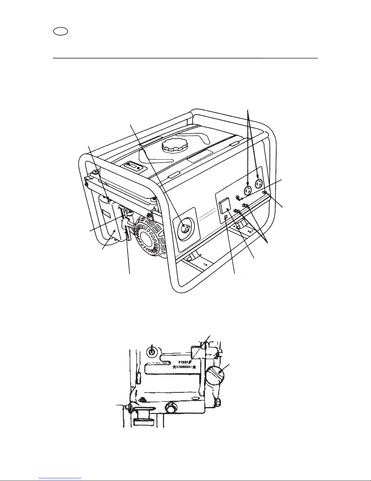
2. COMPONENT IDENTIFICATION
COMPONENT IDENTIFICATION
AC RECEPTACLES
AC CIRCUIT
BREAKER
GROUND
TERMINAL
DC RECEPTACLES
VOLTMETER
DC PROTECTOR
RECOIL STARTER GRIP
AIR CLEANER
FUEL VALVE
CHOKE LEVER
ENGINE SWITCH
ENGINE TYPE & SERIAL NUMBER
OIL FITER CAP
GB
8

Record the engine serial numbers for your future reference.
Refer to these serial number when ordering parts, and when making technical.
Engine serial number:
COMPONENT IDENTIFICATION
GROUND TERMINAL
FUEL TANK CAP
FUEL METER
MUFFLER
SPARK PLUG CAP
VOLMETER
CIRCUIT BREAKER RECEPTACLE
AC OUTPUT TERMINAL
THREE PHASE TYPE
GB
9

3. CONTROLS
1) Engine Switch
The start and stop the engine.
Switch position:
OFF: To stop the engine.
ON: To run the engine.
To engine with electric starter, include the START position.
2) Recoil Starter
To start the engine, pull the starte grip lightly until resistance is felt, then pull briskly.
3) Fuel Valve
The fuel valve is located between the fuel tank and carburetor. When the valve lever is
in the ON position, fuel is allowed to flow from the fuel tank to the carburetor. Be sure
to return the lever to OFF after stopping the engine.
CONTROLS
ENGINE SWITCH
OFF
ON
ENGINE SWITCH
OFF
ON
ENGINE SWITCH
OFF
ON
NOTICE Do not allow the starter to snap back aganist the engine.
Return it gently to prevent damage to the starter.
STARTER GRIP
STARTER GRIP
GB
10
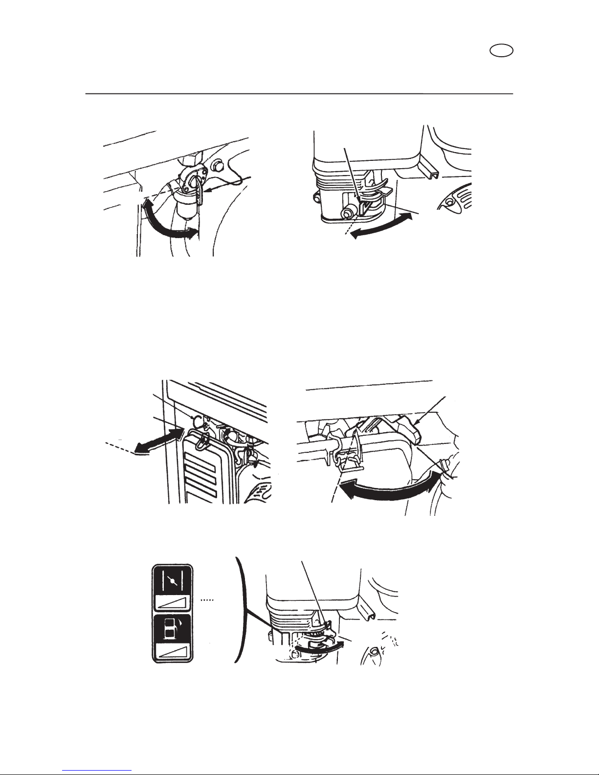
4) Choke
The choke is used to provide an enriched fuel mixture when starting a cold engine. It
can be opened and closed by operating the choke lever or choke rod manually.
Move the lever or the rod to the CLOSE position to enrich the mixture.
CONTROLS
Valve lever
ON
OFF
Valve lever
CHOKE ROD
OPEN
CLOSE
CHOKE LEVER
CLOSED
CHOKE LEVER
OPEN
ON
OFF
OPEN
CLOSE
OPEN
GB
11
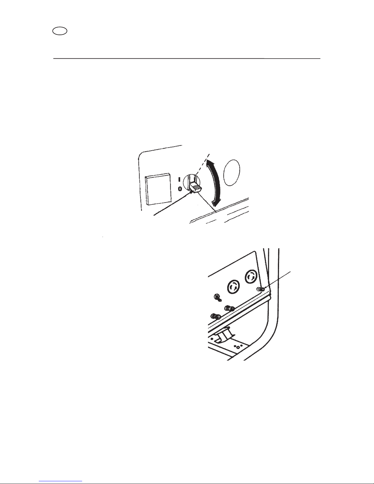
4) Circuit Breaker
The circuit breaker will automatically switch OFF if there is a short circuit or a significant
overlaod of the generator at the receptacle. If the circuit breaker is switched OFF
automatically, check that the appliance is working properly and does not exceed the
rated load capacity of the circuit before swicthing the circuit breaker ON again.
The circuit breaker may be used to switch the generator power ON or OFF.
6) Ground Terminal
The generator ground terminal is connected
to the panel of the generator, the metal
non-current carrying parts of the generator,
and the ground terminals of each receptacle.
Before using the ground terminal, consult a
qualified electrician, eletrical inspector or
local agency having jurisdiction for local
codes or ordinances that apply to the
intended use of the generator.
7) Oil Alert System
The oil alert system is designed to prevent engine damage caused by an insufficient
amount of oil in the crankcase. Before the oil level in the crankcase can fall below a
safe limit, the oil alert system will automatically shut down the engine (the engine
switch wil remain in the ON position). The oil alert system shuts down the engine and
the engine will not start. If this occurs, please check engine oil first.
CONTROLS
CIRCUIT BREAKER
GROUND
TERMINAL
OFF
ON
GB
12

4. GENERATOR USE
1) Connections to a Building’s Electrical System
Connections for standby power to a building’s electrical system must be made by a
qualified electrician. The connection must isolate the generator power from utility power,
and must comply with all applicable laws and electrical codes.
Improper connections to a building’s electrical syatem, can allow
electrical current from the generator to backfeed into the utility lines.
Such backfeed may electrocute utility company workers or others who contact the
lines during a power outage. Consult the utility company or a qualified electrician.
Improper connections to a building’s electrical system can allow
electrical current from the utility company to backfeed into the
generator. When utility power is restored , the generator may explode, burn, or
cause fires in the building’s electrical system.
2) Ground System
To prevent electrical shock from faulty applicances, the generator should be grounded.
Connect a lenght of heavy wire between the ground terminal and the ground source.
The generators have a system ground that connects generator frame components to
the ground terminals in the AC output receptacles. The system ground is not connected
to the AC neutral wire. If the generator is tested by a receptacle tester, it will not show
the same ground circuit condition as for a home receptacle.
Special Requirements
There may be Federal or State Occupational Safety and Health Administration (OSHA)
GENERATOR USE
GROUND
TERMINAL
WARNING
CAUTION
GB
13

regulation, local codes, or ordinances that apply to the intended use of the generator.
Please consult a qualified electrician, elctrical inspector, or the local agency having
jurisdiction.
• In some areas, generators are required to be registered with local utility companies.
• If the generator is used at a construction site, there may be additional regulations
which must be observed.
3) AC Applications
Before connecting an appliance or power cord to the generator:
• Make sure that it is in good working order. Faulty appliances or power cords can
create a potential for electrical shock.
• If an appliance begins to operate abnormally, becomes sluggish or stops suddenly,
turn it off immediately. Disconnect the appliance, and determine whether the problem
is the appliance, or if the rated load capacity of the generator has been exceeded.
• Make sure that the electrical rating of the tool or appliance does not exceed that of
the generator. Never exceed the maximum power rating of the generator. Power levels
between rated and maximum may be used for no more than 30 minutes.
Substantial overloading will switch off the circuit breaker.
Exceeding the time limit maximum power operation or slightly
overloading the generator may not switch the circuit breaker OFF, but will
shorten the service life of the generator.
Limit operation requiring maximum power to 30 minutes.
Maximum power of the LC 1800 DC generator is: 1.5 kW
Maximum power of the LC 2500 DC generator is: 2.2 kW
Maximum power of the LC 3800 DDC generator is: 3.1 kW
Maximum power of the LC 5000 DDC generator is: 4.4 kW
Maximum power of the LC 6500 DDC generator is: 5.5 kW
For continuos operation, do not exceed the rated power.
Rated power of the LC 1800 DC generator is: 1.3 kW
Rated power of the LC 2500 DC generator is: 2.0 kW
Rated power of the LC 3800 DDC generator is: 2.8 kW
Rated power of the LC 5000 DDC generator is: 4.0 kW
Rated power of the LC 6500 DDC generator is: 5.0 kW
In either case, the total power requirements (kW) of all appliances connected must be
GENERATOR USE
NOTICE
GB
14

considered. Appliance and power tool manufacturers usually list rating information near
the model number or serial number.
4) AC Operation
1Start the engine.
2Switch the AC circuit breaker ON.
Rated current of the AC circuit breaker:
LC 1800 DC: 7 A
LC 2500 DC: 10 A
LC 3800 DDC: 13 A
LC 5000 DDC: 19 A
LC 6500 DDC: 23 A
3Plug in the appliance.
Most motorized appliances require more than their rated wattage for startup.
Do not exeed the current limit specified for any one receptacle. If an overload circuit
causes the AC circuit breaker to switch OFF, reduce the electrical load on the circuit,
wait a few minutes and then reset the circuit breaker.
5) DC OPERATION
DC terminals
The DC terminals may ONLY be used
for charging 12 volt automative type
batteries.
The terminal are colored red identify the positive (+) terminal and black to identify
the negative (-) terminal. The battery must be connected to the generator DC terminals
with the proper polarity (battery positive to generator red terminal and battery negative
to the generator black terminal).
GENERATOR USE
NEGATIVE TERMINAL (BLACK)
POSITIVE TERMINAL (RED)
DC PROTECTOR
GB
15

DC Circuit Protector
The DC circuit protector (rated current: 10A) automatically shuts off the DC battery
charging circuit when the DC circuit is overloaded, when there is a problem with the
battery, or the connections between the battery and the genrator are improper.
The indicator inside the DC circuit protector button will pop to show that the DC circuit
protector has switched off. Wait a few minutes and push the button in to reset the DC
circuit protector.
Connecting the battery cables:
1Before connecting charging cables to a battery that is installed in a vehicle, disconnect
the vehicle’s grounded battery cable.
The battery gives off explosive gases; keep sparks, flames and cigarettes
away. Provide adequate ventilation when charging or using batteries.
2Connect the positive (+) battery cable to the battery positive (+) terminal.
3Connect the other end of the positive (+) battery cable to the generator.
4Connect the negative (-) battery cable to the battery negative (-) terminal.
5Connect the other end of the negative (-) battery cable to the generator.
6Start the generator.
Do not start the vehicle while the battery charging cables are
connected and the generator is running. The vehicle or the
generator may be damaged.
An overload DC circuit, excessive current draw by the battery, or a wiring problem
will trip the DC circuit protector (PUSH button extends out). If this happens, wait a few
minutes before pushing in the circuit protector to resume operation. If the circuit
protector continues to go OFF, discontinue charging and see your authorized generator
dealer.
GENERATOR USE
NOTICE
WARNING
GB
16

Disconnecting the battery cables:
1Stop the engine.
2Disconnect the negative (-) battery cable from the generator negative (-) terminal.
3Disconnect the other end of the negative (-) battery cable from the battery negative
(-) terminal.
4Disconnect the positive (+) battery cable from the generator positive (+) terminal.
5Disconnect the other end of the positive (+) battery cable to the battery positive (+)
terminal.
6Connect the vehicle ground cable to the battery negative (-) terminal.
7Reconnect the vehicle grounded battery cable.
6) High Altitude Operation
At high altitude, the standard carburetor air-fuel mixture will be excessively rich.
Performance will decrease, and fuel consumption will increase.
High altitude performance can be improved by installing a smaller diameter main fuel
jet in the carburetor and readjusting the pilot screw. If you always operate the engine
at
altitudes higher than 5000 feet (1500 meters) above sea level, have an authorized
generator dealer perform this carburetor modification.
Even with suitable carburetor jetting, engine horsepower will decrease approzimately
3.5% for each 1000 foot (300 meters) increase in altitude. The effect of altitude on
horsepower will be greater than this if no carburetor modification is made.
If a engine jetted for high altitude is used at a lower altitude,
the lean air fu mixture will reduce performance and may over-
heat and seriously damage the engine.
GENERATOR USE
NOTICE
GB
17

5. PRE-OPERATION CHECK
1) Engine Oil
Engine oil is a major factor affecting engine performance and
service life. Non-detergent and 2-stroke engine oils will damage
the engine and are not recommended.
Check the oil level BEFORE EACH USE with the generator on a level surface with the
engine stopped.
Use 4-stroke oil, premium quality motor oil certified to meet or exceed U.S. automobile
manufacturer’s requirements for Service Classification SG, SF/CC, CD. Motor oils
classified SG, SF/CC, CD will show this
designation on the container.
SAE 10W-30 is recommended for general,
all-temperature use. Other viscosities
shown in the chart may be used when the
average temperature in your area is within
the indicated range.
1. Remove the oil filter cap and wipe the dipstick clean.
2. Check the oil level by inserting the dipstick into the filler neck without screwing it in.
3. If the level is low, add the reccommended oil to the upper mark on the dipstick.
PRE-OPERATION CHECK
NOTICE
AMBIENT TEMPERATURE
OIL FILLER HOLE OIL FILLER CAP
UPPER LEVEL
OIL FILLER CAP
GB
18

2) Fuel
1. Check the fuel level gauge, or check the fuel level after opening the fuel tank cap.
2. Refill the tank if the fuel level is low. Do not fill above the shoulder of the fuel stranier.
• KEEP OUT OF REACH OF CHILDREN.
• Gasoline is extremely flammable and is explosive under certain
conditions.
•Refuel in a well-ventilated area with the engine stopped. Do not smoke or allow
flames or sparks in the area where the engine is refueled or where gasoline is
stored.
•Do not overfill the fuel tank (there should be no fuel in the filler neck). After
refueling, make sure the tank cap is closed properly and securely. Be careful not
to spill fuel when refueling. Spilled fuel vapor may ignite. If any fuel is spilled,
make sure the area is dry before starting the engine.
•Avoid repeated or prolonged contact with skin or breathing of vapor.
Fuel tank capacity:
LC 1800 DC - LC 2500 DC is: 15.0 L
LC 3800 DDC - LC 5000 DDC - LC 6500 DDC is: 25.0 L
Use gasoline with a pump octane rating of 90 or higher.
We recommend unleaded gasoline because it produces fewer engine and spark plug
deposits and extends exhaust system life.
Never use stale or contaminated gasoline or oil/gasoline mixture. Avoid getting dirt or
water in the fuel tank.
Occasionally you may hear light “spark knock” or “pinging” (metallic rapping noise)
while operating under heavy loads. This is no cause for concern.
PRE-OPERATION CHECK
FUEL LEVEL GAUGE
EMPTY
FUEL TANK CAP
UPPER FUEL LEVER
WARNING
OPEN CLOSE
GB
FULL
19

If spark knock or pinging occurs at a steady engine speed, under normal load, change
brands of gasoline. If spark knock or pinging persists, see an authorized generator
dealer.
Running the engine with persistent spark knock or pinging can
cause engine damage.
Running the engine with persistent spark knock or pinging is misuse, and the Distributor’s
Limited Warranty does not cover parts damaged by misuse.
Oxygenated Fuels
Some gasoline are blended with alcohol or an ether compound to increase the octane.
These gasoline are collectively referred to as oxygenated fuels. Some areas of the United
States use oxygenated fuels to help meet clean air standards.
If you use an oxygenated fuel, be sure its pump octane rating is 86 or higher.
Ethanol (ethyl or grain alcohol)
Gasoline containing more than 10% ethanol by volume may cause starting and/or
performance problems. Gasoline containing ethanol may be marketed under the name
“Gasohol”.
Methanol (methyl or wood alcohol)
Gasoline containing methanol must contain cosolvents and corrosion inhibitors to
protect the fuel system. Gasoline containing more than 5% methanol by volume may
cause starting and/or performance problems and may damage metal, rubber and
plastic parts of your fuel system.
MTBE (methyl tertiary butyl ether)
You may use gasoline containing up to 5% MTBE by volume.
Before using an oxygenated fuel, try to confirm the fuel’s contents. Some states (provinces
in Canada) require this information to be posted on the pump. If you notice any undesirable
operating symptoms, switch to a conventional unleaded gasoline. Fuel system damage
or performance problems resulting from the use of an oxigenated fuel are not the
responsibility of manufacturer and are not covered under warranty.
Oxygenated fuels can damage paint and plastic. Be careful not
to spill fuel when filling your fuel tank. Damage caused by spilled
fuel is not covered under warranty.
PRE-OPERATION CHECK
NOTICE
NOTICE
GB
20
This manual suits for next models
4
Table of contents
Languages:


