Altivar Process ATV630 User manual

EAV64301.02.2
www.schneider-electric.com
Alti
var
P
rocess
EAV64301 01/2015
Altivar Process
Variable Speed Drives
ATV630, ATV650
Installation Manual
01/2015

2EAV64301 01/2015
The information provided in this documentation contains general descriptions and/or technical character-
istics of the performance of the products contained herein. This documentation is not intended as a
substitute for and is not to be used for determining suitability or reliability of these products for specific user
applications. It is the duty of any such user or integrator to perform the appropriate and complete risk
analysis, evaluation and testing of the products with respect to the relevant specific application or use
thereof. Neither Schneider Electric nor any of its affiliates or subsidiaries shall be responsible or liable for
misuse of the information contained herein. If you have any suggestions for improvements or amendments
or have found errors in this publication, please notify us.
No part of this document may be reproduced in any form or by any means, electronic or mechanical,
including photocopying, without express written permission of Schneider Electric.
All pertinent state, regional, and local safety regulations must be observed when installing and using this
product. For reasons of safety and to help ensure compliance with documented system data, only the
manufacturer should perform repairs to components.
When devices are used for applications with technical safety requirements, the relevant instructions must
be followed.
Failure to use Schneider Electric software or approved software with our hardware products may result in
injury, harm, or improper operating results.
Failure to observe this information can result in injury or equipment damage.
© 2015 Schneider Electric. All rights reserved.

EAV64301 01/2015 3
Table of Contents
Safety Information . . . . . . . . . . . . . . . . . . . . . . . . . . . . . . . . . . . . . . . . . . . 5
About the Book. . . . . . . . . . . . . . . . . . . . . . . . . . . . . . . . . . . . . . . . . . . . . . 9
Chapter 1 Introduction. . . . . . . . . . . . . . . . . . . . . . . . . . . . . . . . . . . . . . . . . . . . . . . . . 11
Drive Overview . . . . . . . . . . . . . . . . . . . . . . . . . . . . . . . . . . . . . . . . . . . . . . . . . . . . . . . . . . . 12
Accessories and Options. . . . . . . . . . . . . . . . . . . . . . . . . . . . . . . . . . . . . . . . . . . . . . . . . . . . 17
Steps for setting up the drive. . . . . . . . . . . . . . . . . . . . . . . . . . . . . . . . . . . . . . . . . . . . . . . . . 18
Preliminary Instructions . . . . . . . . . . . . . . . . . . . . . . . . . . . . . . . . . . . . . . . . . . . . . . . . . . . . . 19
Chapter 2 Technical Data . . . . . . . . . . . . . . . . . . . . . . . . . . . . . . . . . . . . . . . . . . . . . . 21
2.1 Environment Data . . . . . . . . . . . . . . . . . . . . . . . . . . . . . . . . . . . . . . . . . . . . . . . . . . . . . . . . . 22
Temperature Conditions . . . . . . . . . . . . . . . . . . . . . . . . . . . . . . . . . . . . . . . . . . . . . . . . . . . . 23
Altitude Conditions. . . . . . . . . . . . . . . . . . . . . . . . . . . . . . . . . . . . . . . . . . . . . . . . . . . . . . . . . 23
2.2 Mechanical Data . . . . . . . . . . . . . . . . . . . . . . . . . . . . . . . . . . . . . . . . . . . . . . . . . . . . . . . . . . 24
Dimensions and Weights. . . . . . . . . . . . . . . . . . . . . . . . . . . . . . . . . . . . . . . . . . . . . . . . . . . . 24
2.3 Electrical Data . . . . . . . . . . . . . . . . . . . . . . . . . . . . . . . . . . . . . . . . . . . . . . . . . . . . . . . . . . . . 39
Drive Ratings In Normal Duty . . . . . . . . . . . . . . . . . . . . . . . . . . . . . . . . . . . . . . . . . . . . . . . . 40
Drive Ratings In Heavy Duty . . . . . . . . . . . . . . . . . . . . . . . . . . . . . . . . . . . . . . . . . . . . . . . . . 43
Derating Curves. . . . . . . . . . . . . . . . . . . . . . . . . . . . . . . . . . . . . . . . . . . . . . . . . . . . . . . . . . . 46
Sink / Source Switch Configuration . . . . . . . . . . . . . . . . . . . . . . . . . . . . . . . . . . . . . . . . . . . . 50
Chapter 3 Drive Mounting . . . . . . . . . . . . . . . . . . . . . . . . . . . . . . . . . . . . . . . . . . . . . . 53
Mounting Conditions . . . . . . . . . . . . . . . . . . . . . . . . . . . . . . . . . . . . . . . . . . . . . . . . . . . . . . . 54
Mounting Procedures . . . . . . . . . . . . . . . . . . . . . . . . . . . . . . . . . . . . . . . . . . . . . . . . . . . . . . 59
Chapter 4 Drive wiring . . . . . . . . . . . . . . . . . . . . . . . . . . . . . . . . . . . . . . . . . . . . . . . . . 63
Wiring Instructions . . . . . . . . . . . . . . . . . . . . . . . . . . . . . . . . . . . . . . . . . . . . . . . . . . . . . . . . . 64
Cable Length Instructions . . . . . . . . . . . . . . . . . . . . . . . . . . . . . . . . . . . . . . . . . . . . . . . . . . . 66
Wiring Diagrams . . . . . . . . . . . . . . . . . . . . . . . . . . . . . . . . . . . . . . . . . . . . . . . . . . . . . . . . . . 67
Characteristics of the Power Part Terminals . . . . . . . . . . . . . . . . . . . . . . . . . . . . . . . . . . . . . 69
Wiring the Power Part . . . . . . . . . . . . . . . . . . . . . . . . . . . . . . . . . . . . . . . . . . . . . . . . . . . . . . 73
Electromagnetic Compatibility . . . . . . . . . . . . . . . . . . . . . . . . . . . . . . . . . . . . . . . . . . . . . . . . 80
Operation on an IT or Corner Grounded System . . . . . . . . . . . . . . . . . . . . . . . . . . . . . . . . . 82
Control Terminals Electrical Data . . . . . . . . . . . . . . . . . . . . . . . . . . . . . . . . . . . . . . . . . . . . . 86
Arrangement and Characteristics of Control Block Terminals and Communication and I/O
Ports . . . . . . . . . . . . . . . . . . . . . . . . . . . . . . . . . . . . . . . . . . . . . . . . . . . . . . . . . . . . . . . . . . . 88
Wiring The Control Part . . . . . . . . . . . . . . . . . . . . . . . . . . . . . . . . . . . . . . . . . . . . . . . . . . . . . 90
Chapter 5 Checking Installation . . . . . . . . . . . . . . . . . . . . . . . . . . . . . . . . . . . . . . . . . 91
Check List Before Switching On . . . . . . . . . . . . . . . . . . . . . . . . . . . . . . . . . . . . . . . . . . . . . . 91
Chapter 6 Maintenance . . . . . . . . . . . . . . . . . . . . . . . . . . . . . . . . . . . . . . . . . . . . . . . . 93
Scheduled servicing . . . . . . . . . . . . . . . . . . . . . . . . . . . . . . . . . . . . . . . . . . . . . . . . . . . . . . . 93

4EAV64301 01/2015

EAV64301 01/2015 5
Safety Information
Important Information
NOTICE
Read these instructions carefully, and look at the equipment to become familiar with the device before
trying to install, operate, or maintain it. The following special messages may appear throughout this
documentation or on the equipment to warn of potential hazards or to call attention to information that
clarifies or simplifies a procedure.
PLEASE NOTE
Electrical equipment should be installed, operated, serviced, and maintained only by qualified personnel.
No responsibility is assumed by Schneider Electric for any consequences arising out of the use of this
material.
A qualified person is one who has skills and knowledge related to the construction and operation of
electrical equipment and its installation, and has received safety training to recognize and avoid the
hazards involved.
Qualification Of Personnel
Only appropriately trained persons who are familiar with and understand the contents of this manual and
all other pertinent product documentation are authorized to work on and with this product. In addition, these
persons must have received safety training to recognize and avoid hazards involved. These persons must
have sufficient technical training, knowledge and experience and be able to foresee and detect potential
hazards that may be caused by using the product, by changing the settings and by the mechanical,
electrical and electronic equipment of the entire system in which the product is used. All persons working
on and with the product must be fully familiar with all applicable standards, directives, and accident
prevention regulations when performing such work.

6EAV64301 01/2015
Intended Use
This product is a drive for three-phase synchronous and asynchronous motors and intended for industrial
use according to this manual.The product may only be used in compliance with all applicable safety
regulations and directives, the specified requirements and the technical data.Prior to using the product, you
must perform a risk assessment in view of the planned application. Based on the results, the appropriate
safety measures must be implemented.Since the product is used as a component in an entire system, you
must ensure the safety of persons by means of the design of this entire system (for example, machine
design). Any use other than the use explicitly permitted is prohibited and can result in hazards. Electrical
equipment should be installed, operated, serviced, and maintained only by qualified personnel.
Product Related Information
Read and understand these instructions before performing any procedure with this drive.
DANGER
HAZARD OF ELECTRIC SHOCK, EXPLOSION OR ARC FLASH
zOnly appropriately trained persons who are familiar with and understand the contents of this manual
and all other pertinent product documentation and who have received safety training to recognize and
avoid hazards involved are authorized to work on and with this drive system. Installation, adjustment,
repair and maintenance must be performed by qualified personnel.
zThe system integrator is responsible for compliance with all local and national electrical code
requirements as well as all other applicable regulations with respect to grounding of all equipment.
zMany components of the product, including the printed circuit boards, operate with mains voltage. Do
not touch. Use only electrically insulated tools.
zDo not touch unshielded components or terminals with voltage present.
zMotors can generate voltage when the shaft is rotated. Prior to performing any type of work on the
drive system, block the motor shaft to prevent rotation.
zAC voltage can couple voltage to unused conductors in the motor cable. Insulate both ends of unused
conductors of the motor cable.
zDo not short across the DC bus terminals or the DC bus capacitors or the braking resistor terminals.
zBefore performing work on the drive system:
zDisconnect all power, including external control power that may be present.
zPlace a Do Not Turn On label on all power switches.
zLock all power switches in the open position.
zWait 15 minutes to allow the DC bus capacitors to discharge. The DC bus LED is not an indicator
of the absence of DC bus voltage that can exceed 800 Vdc.
Measure the voltage on the DC bus between the DC bus terminals (PA/+, PC/-) using a properly
rated voltmeter to verify that the voltage is <42 Vdc
zIf the DC bus capacitors do not discharge properly, contact your local Schneider Electric represen-
tative. Do not repair or operate the product.
zInstall and close all covers before applying voltage.
Failure to follow these instructions will result in death or serious injury.
WARNING
UNEXPECTED MOVEMENT
Drive systems may perform unexpected movements because of incorrect wiring, incorrect settings,
incorrect data or other errors.
zCarefully install the wiring in accordance with the EMC requirements.
zDo not operate the product with unknown or unsuitable settings or data.
zPerform a comprehensive commissioning test.
Failure to follow these instructions can result in death, serious injury, or equipment damage.

EAV64301 01/2015 7
Damaged products or accessories may cause electric shock or unanticipated equipment operation.
Contact your local Schneider Electric sales office if you detect any damage whatsoever.
(1) For USA: Additional information, refer to NEMA ICS 1.1 (latest edition), Safety Guidelines for the
Application, Installation, and Maintenance of Solid State Control and to NEMA ICS 7.1 (latest edition),
Safety Standards for Construction and Guide for Selection, Installation and Operation of Adjustable-Speed
Drive Systems.
DANGER
ELECTRIC SHOCK OR UNANTICIPATED EQUIPMENT OPERATION
Do not use damaged products or accessories.
Failure to follow these instructions will result in death or serious injury.
WARNING
LOSS OF CONTROL
zThe designer of any control scheme must consider the potential failure modes of control paths and,
for critical control functions, provide a means to achieve a safe state during and after a path failure.
Examples of critical control functions are emergency stop, overtravel stop, power outage and restart.
zSeparate or redundant control paths must be provided for critical control functions.
zSystem control paths may include communication links. Consideration must be given to the
implications of unanticipated transmission delays or failures of the link.
zObserve all accident prevention regulations and local safety guidelines (1).
zEach implementation of the product must be individually and thoroughly tested for proper operation
before being placed into service.
Failure to follow these instructions can result in death, serious injury, or equipment damage.
NOTICE
DESTRUCTION DUE TO INCORRECT MAINS VOLTAGE
Before switching on and configuring the product, verify that it is approved for the mains voltage
Failure to follow these instructions can result in equipment damage.
WARNING
HOT SURFACES
zEnsure that any contact with hot surfaces is avoided.
zDo not allow flammable or heat-sensitive parts in the immediate vicinity of hot surfaces.
zVerify that the heat dissipation is sufficient by performing a test run under maximum load conditions.
Failure to follow these instructions can result in death, serious injury, or equipment damage.

8EAV64301 01/2015

EAV64301 01/2015 9
About the Book
At a Glance
Document Scope
The purpose of this document is:
zto give you mechanical and electrical information related to the Altivar Process drive,
zto show you how to install and wire this drive.
Validity Note
NOTE: The products listed in the document are not all available at the time of publication of this document
online. The data, illustrations and product specifications listed in the guide will be completed and updated
as the product availabilities evolve. Updates to the guide will be available for download once products are
released on the market.
This documentation is valid for the Altivar Process drive.
The technical characteristics of the devices described in this document also appear online. To access this
information online:
The characteristics that are presented in this manual should be the same as those characteristics that
appear online. In line with our policy of constant improvement, we may revise content over time to improve
clarity and accuracy. If you see a difference between the manual and online information, use the online
information as your reference.
Step Action
1 Go to the Schneider Electric home page www.schneider-electric.com.
2 In the Search box type the reference of a product or the name of a product range.
zDo not include blank spaces in the model number/product range.
zTo get information on grouping similar modules, use asterisks (*).
3 If you entered a reference, go to the Product Datasheets search results and click on the
reference that interests you.
If you entered the name of a product range, go to the Product Ranges search results and click
on the product range that interests you.
4 If more than one reference appears in the Products search results, click on the reference that
interests you.
5 Depending on the size of your screen, you may need to scroll down to see the data sheet.
6 To save or print a data sheet as a .pdf file, click Download XXX product datasheet.

10 EAV64301 01/2015
Related Documents
Use your tablet or your PC to quickly access detailed and comprehensive information on all our products
on www.schneider-electric.com
The internet site provides the information you need for products and solutions
zThe whole catalog for detailed characteristics and selection guides
zThe CAD files to help design your installation, available in over 20 different file formats
zAll software and firmware to maintain your installation up to date
zA large quantity of White Papers, Environment documents, Application solutions, Specifications... to
gain a better understanding of our electrical systems and equipment or automation
zAnd finally all the User Guides related to your drive, listed below:
You can download these technical publications and other technical information from our website at
www.schneider-electric.com.
Standards and Terminology
The technical terms, terminology, and the corresponding descriptions in this manual normally use the
terms or definitions in the relevant standards.
In the area of drive systems this includes, but is not limited to, terms such as error, error message, failure,
fault, fault reset, protection, safe state, safety function, warning, warning message, and so on.
Among others, these standards include:
zIEC 61800 series: Adjustable speed electrical power drive systems
zIEC 61508 Ed.2 series: Functional safety of electrical/electronic/programmable electronic safety-related
zEN 954-1 Safety of machinery - Safety related parts of control systems
zEN ISO 13849-1 & 2 Safety of machinery - Safety related parts of control systems.
zIEC 61158 series: Industrial communication networks - Fieldbus specifications
zIEC 61784 series: Industrial communication networks - Profiles
zIEC 60204-1: Safety of machinery - Electrical equipment of machines – Part 1: General requirements
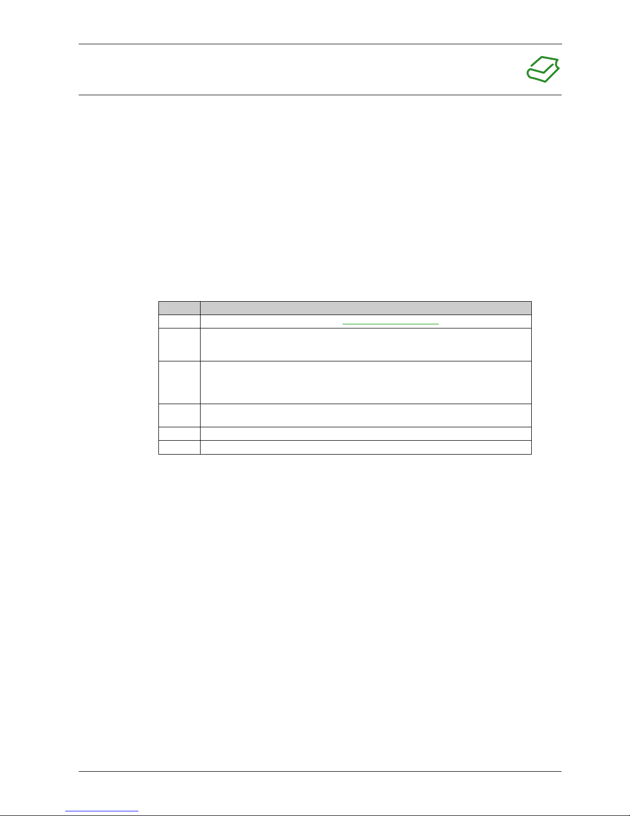
Title of Documentation Reference Number
Altivar Process Getting Started EAV63253 (English), EAV63254 (French),
EAV63255 (German), EAV63256 (Spanish),
EAV64310 (Italian), EAV64298 (Chinese)
Altivar Process Getting Started Annex (SCCR) EAV64300 (English)
Altivar Process Installation Manual EAV64301 (English), EAV64302 (French),
EAV64306 (German), EAV64307 (Spanish),
EAV63257 (Italian), EAV64317 (Chinese)
Altivar Process Programming Manual EAV64318 (English), EAV64320 (French),
EAV64321 (German), EAV64322 (Spanish),
EAV64323 (Italian), EAV64324 (Chinese)
Altivar Process Modbus Serial Link Manual (Embedded) EAV64325 (English)
Altivar Process Ethernet Manual (Embedded) EAV64327 (English)
Altivar Process Ethernet IP - Modbus TCP Manual (VW3A3720) EAV64328 (English)
Altivar Process PROFIBUS DP manual (VW3A3607) EAV64329 (English)
Altivar Process DeviceNet manual (VW3A3609) EAV64330 (English)
Altivar Process PROFINET manual (VW3A3627) EAV64331 (English)
Altivar Process CANopen Serial Link Manual (VW3A3608, 618, 628) EAV64333 (English)
Altivar Process Communication Parameters EAV64332 (English)
Altivar Process Safety Function manual EAV64334 (English)

EAV64301 01/2015 11
Alti
var
P
rocess
EAV64301 01/2015
Introducti on
Chapter 1
Introduction
What Is in This Chapter?
This chapter contains the following topics:
Topic Page
Drive Overview 12
Accessories and Options 17
Steps for setting up the drive 18
Preliminary Instructions 19

12 EAV64301 01/2015
Drive Overview
Frame Sizes for IP21 Products
The family of Altivar Process includes 6 frame sizes for IP21 products.
Frame size 1 Frame size 2
z3-phase 200...240 V, 0.75...4 kW, 1...5 HP
z3-phase 380...480 V, 0.75...5.5 kW, 1...7 1/2 HP
z3-phase 200...240 V, 5.5 kW, 7 1/2 HP
z3-phase 380...480 V, 7.5...11 kW, 10...15 HP
ATV630U07M3...U40M3, ATV630U07N4...U55N4 ATV630U55M3, ATV630U75N4, ATV630D11N4
Frame size 3 Frame size 4
z3-phase 200...240 V, 7.5 kW, 11 kW, 10 HP, 15 HP
z3-phase 380...480 V, 15...22 kW, 20...30 HP
z3-phase 200...240 V 15...22 kW, 20...30 HP
z3-phase 380...480 V, 30...45 kW, 40...60 HP
ATV630D11M3, ATV630U75M3,
ATV630D15N4...D22N4
ATV630D15M3...ATV630D22M3,
ATV630D30N4...ATV630D45N4

EAV64301 01/2015 13
Frame size 5 Frame size 6
z3-phase 200...240 V, 30...45 kW
40...60 HP
z3-phase 380...480 V, 55, 75 and 90 kW
75, 100 and 125 HP
z3-phase 200...240 V, 55 and 75 kW
75...100 HP
z3-phase 380...480 V, 110...160 kW
150...250 HP
ATV630D30M3...D45M3, ATV630D55N4...D90N4 ATV630D55M3, ATV630D75M3,
ATV630C11N4...C16N4,

14 EAV64301 01/2015
Frame Sizes for IP55 Products
The family of Altivar Process includes 3 frame sizes for IP55 products, with or without integrated
load switch.
Frame size A
z3-phase 380...480 V, 0.75...22 kW
1...30 HP, with or without Vario load switch
ATV650U07N4(E)*...U75N4(E)*,
ATV650D11N4(E)*...D22N4(E)*
(E)*= product included a Vario load switch

EAV64301 01/2015 15
Frame size B Frame size C
z3-phase 380...480 V, 30...45 kW
40...60 HP, with or without Vario load switch
z3-phase 380...480 V, 55...90 kW
75...125 HP, with or without Vario load switch
ATV650D30N4(E)*...D45N4(E)* ATV650D55N4(E)*...D90N4(E)*
(E)*= product included a Vario load switch

16 EAV64301 01/2015
Catalog Number Description
NOTE: see the catalog for possible combinations.
Nameplate example
The nameplate contains the following data:
Product type Catalog number Power rating
Firmware version Power part supply
Fuses and overload protection information Power part cable information
Degree of protection Certifications Serial number
A
TV630U40N4
V1.0 IE00
4kW - 5HP
6W0502001001
Made in Indonesia
1.8 N.m
Cu AWG14 75° C
HP
U (V~)
F (Hz)
I (A)
380 - 480 3
50 / 60
7.6 max
0...380 - 480 3
0...500
9.3
kW
U (V~)
F (Hz)
I (A) 7.6 max
0...500
15.9 lb.in
Altivar 630
SCCR : for rating and protection refer to Annex
of the getting started
IP21
Internal Motor Overload Protection - Class 10
380 - 480 3 0...380 - 480 3
50 / 60
9.3
Input Output
FR 92506 Rueil Malmaison

EAV64301 01/2015 17
Accessories and Options
Introduction
Altivar Process drives are designed to take numerous accessories and options to increase their
functionality. For a detailed description and catalog numbers, refer to the Catalog on schneider-
electric.com
All accessories and options come with an instruction sheet to help installation and commisioning.
Therefore you will only find here a short product description.
Accessories
Drive
zFan replacement kit
Graphic display terminal
zRemote mounting kit for mounting on enclosure door
zMultidrop connection accessories for connecting several drives to the RJ45 terminal port
Drive mounting kits
zFlush-mounting kit for separate air flow
zWall mounting kit for drives with push through
zMetal conduit box
Option Modules
I/O expansion
zDigital and analog I/O module
zRelay output module
Communication
zEtherNet/IP and Modbus TCP dual port
zCANopen daisy chaind
zCANopen SUB-D
zCANopen screw terminal block
zProfiNet
zPROFIBUS DP V1
zDeviceNet
Filters
Passive filters
EMC input filters
Output filters
zdv/dt filters
zSinus filters

18 EAV64301 01/2015
Steps for setting up the drive
Procedure

EAV64301 01/2015 19
Preliminary Instructions
Handling and Storage
To help protect the drive before installation, handle and store the device in its packaging. Ensure that the
ambient conditions are acceptable.
Handling the Drive
Altivar Process drives of frame size A, B and C, and frame sizes 1 up to 3 can be removed from their
packaging and installed without a handling device.
Higher drive frame sizes require a handling device; for this reason, these drives all have lifting lugs.
Check the Delivery of the Drive
Damaged products or accessories may cause electric shock or unanticipated equipment operation.
Contact your local Schneider Electric sales office if you detect any damage whatsoever.
WARNING
DANGEROUS HANDLING
zDo not handle a damaged packaging.
zFollow the handling instructions.
zOpen and handle the packaging with care.
Failure to follow these instructions can result in death, serious injury, or equipment damage.
DANGER
ELECTRIC SHOCK OR UNANTICIPATED EQUIPMENT OPERATION
Do not use damaged products or accessories.
Failure to follow these instructions will result in death or serious injury.
Step Action
1 Remove the drive from the packaging and verify that it has not been damaged
2 Verify that the catalog number printed on the nameplate (see page 16)corresponds to the
purchase order.

20 EAV64301 01/2015
Other manuals for ATV630
1
This manual suits for next models
1
Table of contents
Other Altivar Process Inverter manuals
Popular Inverter manuals by other brands

INVENTOR
INVENTOR V2KI-12 owner's manual

EINHELL
EINHELL BT-PG 5500/2 D operating instructions

Sealey
Sealey MW140.V2 instructions

GYS
GYS Gysflash 70-24 HF manual

Tektronix
Tektronix AFG31000 Series Specification and Performance Verification Technical Reference

Siemens
Siemens Sinamics CU240D-2 DP operating instructions