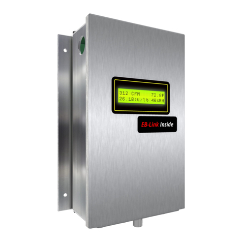
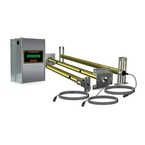
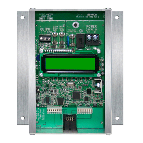
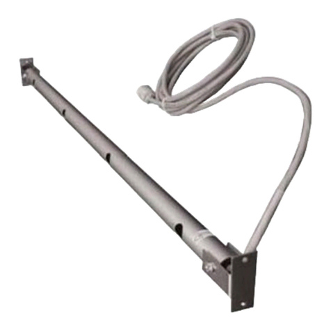
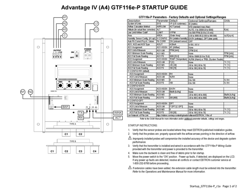
Ebtron Advantage IV Series Manual

©2020 EBTRON, Inc. ALL RIGHTS RESERVED
Advantage IV and EB-Flow2Product Lines
O&M MANUAL
Updated March 30, 2021
EBTRON, Inc.
1663 Hwy 701 South, Loris SC29569
Toll Free: 1-800-2EBTRON (1-800-232-8766)
FAX: 1-843-465-0450
Internet: EBTRON.com


Advantage IV and EB-Flow2Product Lines
O&M MANUAL
foreword
0-O&M_Foreword_r1f forewordPage 1
EBTRON, Inc • 1663 Hwy 701 S., Loris, SC 29569 • Toll Free: 800-2EBTRON (232-8766) • Fax: 843-756-1828 • EBTRON.com
Thank you for choosing EBTRON airflow measurement equipment. EBTRON has been the leader
in airflow measurement for monitoring and control since 1983. Our advanced thermal dispersion
measurement technology has been copied by others but duplicated by none.
We are supported by an extensive, factory trained, local representative network that is available to
support all of your needs. We also provide toll-free factory support at 800-2EBTRON (232-8766),
Monday through Thursday 8:00 AM to 4:30 PM and Friday 8:00 AM to 2:00 PM eastern time.
Don’t know who your local EBTRON representative is? Visit EBTRON.com and click on the REP
FINDER button.
This manual has been developed as a comprehensive guide to our Advantage IV and EB-Flow2 product lines.
It is structured as a complete, single source, reference manual and contains the following information:
•FCC Part 15 Compliance Statement
•Section 1 – Installation
•Section 2 – Startup
•Section 3 – Custom Configuration
•Section 4 – Built-in Tools
•Section 5 – Diagnostics
•Section 6 – Troubleshooting
•Section 7 – Maintenance
•Appendix A – Placement Guidelines
•Appendix B – Sensor Probe Installation Guides
•Appendix C – Transmitter Installation Guides
•Appendix D – Wiring Guides
•Appendix E – Startup Guides
•Appendix F – Network Registers and Object Lists
•Appendix G – Mechanical Drawings
The following symbols are used in this manual:
IMPORTANT. The comment is very important and should not be ignored.
INFORMATION. The comment provides additional information.
SUGGESTION. The comment is a suggestion to the user.

Advantage IV and EB-Flow2Product Lines
O&M MANUAL
FCC-Part 15 Compliance
FCC_Part-15_Compliance_r1c Page 1
EBTRON, Inc • 1663 Hwy 701 S., Loris, SC 29569 • Toll Free: 800-2EBTRON (232-8766) • Fax: 843-756-1828 • EBTRON.com
ALL GTx116, GTx116e, GTx208e, GTx108, GTx108e and GTx204e Models contain transmitter module:
FCC ID: T9JRN4020 / IC: 6514A-RN4020
GTW116 and GTW108 Models also contain transmitter module:
FCC ID: OJM900MCA / IC: 5840A-900MCA
Altering the transmitter module(s) or using an antenna other than an Ebtron approved antenna with the transmitter module(s) could void the users’ authority to operate
the equipment.
Note: The OJM900MCA (IC: 5840A-900MCA) transmitter module has been co-location verified with the T9JRN4020 (IC: 6514A-RN4020).
The above transmitter enabled Ebtron models comply with Part 15 of the FCC rules and Industry Canada license-exempt RSS standards.
(The above transmitter module enabled Ebtron models complies with Industry Canada License-exempt RSS standards.)
Les modèles Ebtron activés pour le module émetteur ci-dessus sont conformes aux normes RSS exemptes de licence d'Industrie Canada.
All above models and the EF-x1000, EF-x2000, HTx104, HTx202 Ebtron models comply with Part 15 of the FCC rules and Industry Canada ICES-003. Operation of
these devices is subject to the following two conditions:
1. This device may not cause harmful interference, and
2. This device must accept any interference received, including interference that may cause undesired operation.
This equipment has been tested and found to comply with the limits for a Class A digital device, pursuant to part 15 of the FCC Rules and Industry Canada ICES-003.
These limits are designed to provide reasonable protection against harmful interference when the equipment is operated in a commercial environment. This equipment
generates, uses, and can radiate radio frequency energy and, if not installed and used in accordance with the instruction manual, may cause harmful interferences to
radio communications. Operations of this equipment in a residential area is likely to cause harmful interference in which case the user will be required to correct the
interference at his own expense.
(All above Ebtron models are Class A digital apparatus and complies with Canadian ICES-003.
Operation of these devices is subject to the following two conditions: 1 This device may not cause harmful interference, and 2. This device must accept any
interference received, including interference that may cause undesired operation.)
Tous les modèles Ebtron ci-dessus sont des appareils numériques de classe A et sont conformes à la norme ICES-003 canadienne. Le fonctionnement de ces
appareils est soumis aux deux conditions suivantes: 1 Cet appareil ne doit pas provoquer d'interférences nuisibles, et 2. Cet appareil doit accepter toute interférence
reçue, y compris les interférences susceptibles de provoquer un fonctionnement indésirable.
Under Industry Canada regulations, the noted radio transmitters may only operate using an antenna of a type and maximum (or lesser) gain approved for the
transmitter by Industry Canada. To reduce potential radio interference to other users, the antenna type and its gain should be so chosen that the equivalent
isotropically radiated power (e.i.r.p) is not more than that necessary for successful communication.
Conformément à la réglementation d'Industrie Canada, le présent émetteur radio peut fonctionner avec
une antenne d'un type et d'un gain maximal (ou inférieur) approuvé pour l'émetteur par Industrie Canada. Dans le but de réduire les risques de brouillage
radioélectrique à l'intention des autres utilisateurs, il faut choisir le type d'antenne et son gain de sorte que la puissance isotrope rayonnée équivalente (p.i.r.e.) ne
dépasse pas l'intensité nécessaire à l'établissement d'une communication satisfaisante.

Advantage IV and EB-Flow2Product Lines
O&M MANUAL
Section 1 – Installation
1-O&M_Installation_r1d Section 1Page 1
EBTRON, Inc • 1663 Hwy 701 S., Loris, SC 29569 • Toll Free: 800-2EBTRON (232-8766) • Fax: 843-756-1828 • EBTRON.com
1. SECTION OVERVIEW
This section provides installation and wiring instructions for Advantage IV and EB-Flow2 remote transmitters.
1.1. SENSOR PROBES SUPPORTED
Transmitters in this manual support the following sensor probe types:
•-P duct/plenum probe
•-U universal mount probe
•-T terminal unit small duct probe
•-F fan inlet probe
•-B bleed sensor probe
1.2. SENSOR PROBE MOUNTING
1.2.1. Locating Probes
Sensor probe placement guidelines are located in the Appendix A – Placement Guidelines section at the end
of this document.
If minimum placement guidelines cannot be achieved, installed accuracy may be compromised.
Transmitters can be field adjusted to match a third-party measurement. Adjusted field measurements
typically result in comparative readings within ±3% of the third-party measurement. Be advised that
the third-party measurement may have uncertainties greater than or equal to ±10% and should only
be used to adjust the airflow measurement device if the probes do not meet minimum placement
requirements and the discrepancy is greater than the uncertainty of the third-party source.
1.2.2. Installation
Installation guides for each probe type are located in the Appendix B – Sensor Probe Installation Guides
section at the end of this document.
Sensor probes must be mounted and spaced properly to achieve the specified installed accuracy.
1.3. TRANSMITTER MOUNTING
Installation guides for each transmitter model are located in the Appendix C – Transmitter Installation Guides
section at the end of this document.
Mount transmitters in a location protected from moisture, rain and snow with an ambient temperature between
-20 and 120 °F [-28.9 to 48.9 °C]. Provide a weatherproof enclosure and mount away from direct sunlight
when outdoor mounting is required.
Transmitters have an LCD and four-button user interface. Select a mounting location where the LCD and
pushbutton interface are accessible during normal operation.

1-O&M_Installation_r1d Section 1Page 2
EBTRON, Inc • 1663 Hwy 701 S., Loris, SC 29569 • Toll Free: 800-2EBTRON (232-8766) • Fax: 843-756-1828 • EBTRON.com
The cover of the Advantage IV Gold Series transmitter hinges up for removal. The cover of the Advantage IV
Hybrid Series transmitter slides up and out of the enclosure. The cover of the EB-Flow2transmitter is
secured by four #1 Philips head screws.
Make sure the transmitter is located where all of the cables from the sensor probes reach the
transmitter.
Provide a minimum of 6.5 inches [165 mm] above Hybrid Series transmitters to allow for cover
removal when slide out covers are provided.
Provide a minimum of 3 inches [76 mm] below all transmitters to connect cable plugs from the sensor
probes.
1.4. TRANSMITTER WIRING
Wiring guides for each transmitter model are located in the Appendix D – Wiring Guides section at the end of
this document.
1.4.1. Probe Connections to Transmitter
Each probe has a tag on the cable plug and probe bracket/tube with a TAG ID set to the location name
(NAME) provided at the time of order. If a location name is not provided the TAG ID is set to null (no value).
Multiple connector arrangements do not require probes be installed in each receptacle.
Sensor probe plugs are keyed and NOT twist-lock. Align the key and push the plug onto the
transmitter receptacle. Twisting the connector onto the receptacle will cause damage and void
warranty.
Probes are “plug and play” and do not need to be connected to a specific receptacle for proper operation.
However, use of the following connection convention simplifies sensor node location identification when using
the EB-Link Reader or when viewing individual sensor node data using DIAGNOSTICS. Although not
required, it is a good practice to install each probe in the corresponding connector. Probes should also be
installed sequentially by the labeled probe number, top to bottom, left to right or vice versa in the duct, plenum
or fan array.
Depending on the model, up to 8 sensor nodes can be provided in a single probe. A probe number is labeled
on each probe hang tag (Probe x of y). The leftmost receptacle used on the transmitter when viewed from the
display side is always designated as Connector 1 (C1). Additional connectors increment sequentially from left
to right on transmitters with more than one receptacle. Fan array models with two rows of 4 receptacles,
increment left to right, C1 to C4 on the topmost row closest to the cover, then left to right, C5 to C8 on the
lower most row.
Fan array models (-F/An) must follow this convention if two probes are located in each fan inlet and
the individual fan airflow rates are required and/or the fan alarm is enabled (i.e. put probes for fan 1 in
C1 and C2, fan 2 in C3 and C4, etc.)
Probe numbers (P1 to Py) are dynamically assigned by the transmitter after initial power up, left to right,
based on the connector receptacle used.The sensor node furthest from the cable side of the probe on
probes with more than one sensor node, is designated as “Sensor Node 1”.

1-O&M_Installation_r1d Section 1Page 3
EBTRON, Inc • 1663 Hwy 701 S., Loris, SC 29569 • Toll Free: 800-2EBTRON (232-8766) • Fax: 843-756-1828 • EBTRON.com
1.4.1.1. SPECIAL CONSIDERATIONS FOR DUAL LOCATION TRANSMITTERS
The number of locations is designated by the fourth digit in the model code of Advantage IV transmitters (ex.
GTx116e is single location, GTx208e is dual location). EB-Flow2 transmitters can be configured for two
locations in the field.
Two location transmitters with two connectors use the leftmost connector when viewed from the display side
as “Location 1” and the rightmost connector as “Location 2”. Transmitters with 4 connectors use the leftmost
two connectors as “Location 1” and the rightmost two connectors as “Location 2”. Transmitters with 8
connectors use the top four connectors relative to the cover as “Location 1” and the bottom four connectors
as “Location 2”.
Probes have the suffix AMD-1 and AMD-2 appended to the TAG ID for “Location 1” and “Location 2”
respectively for identification.
1.4.2. B.A.S. and Power Connections
B.A.S. and power connections for each transmitter model are located in the Appendix D – Wiring Guides
section at the end of this document.
1.4.2.1. SIGNAL ISOLATION
1.4.2.1.1. Advantage IV Models
All Advantage IV transmitter models are provided with isolated analog output signals and network
connections.
1.4.2.1.2. EB-Flow2 Models
All EB-Flow2 transmitter models are provided with non-isolated analog output signals and network
connections.
Isolation is typically required and achieved by providing power with a transformer where the
secondary is not connected to earth ground.
EBTRON can provide and optional signal isolator for RS-485 network applications.
1.5. POWER UP
Refer to Section 2 – Startup and the individual startup guides located in Appendix E – Startup Guides at the
end of this document prior to moving the power switch to the “ON” position.
1.6. FOR MORE INFORMATION …
For toll-free factory support call 800-2EBTRON (232-8766), Monday through Thursday 8:00 AM to 4:30 PM
and Friday 8:00 AM to 2:00 PM eastern time or contact your local representative.


Advantage IV and EB-Flow2Product Lines
O&M MANUAL
Section 2 – Startup
2-O&M_Startup_r1l Section 2Page 1
EBTRON, Inc • 1663 Hwy 701 S., Loris, SC 29569 • Toll Free: 800-2EBTRON (232-8766) • Fax: 843-756-1828 • EBTRON.com
2. SECTION OVERVIEW
This section discusses startup and basic operation. Advantage IV and EB-Flow2remote transmitters are
“plug-and-play.” Transmitters are designed to be fully functional at power-up. Field configuration is generally
only required when factory default output signals and/or network parameters must be modified for the host
building automation system or application controller.
2.1. PRE-POWER CHECKS
2.1.1. Sensor Probe Installation
Inspect and verify the following:
The location where the probes are located meet or exceed EBTRON published placement guidelines
for the sensor probe model and sensor density provided.
If minimum placement guidelines cannot be achieved, installed accuracy may be compromised.
Transmitters can be field adjusted to match a third-party measurement. Adjusted field measurements
typically result in comparative readings within ±3% of the third-party measurement. Be advised that
the third-party measurement may have uncertainties greater than or equal to ±10% and should only
be used to adjust the airflow measurement device if the probes do not meet minimum placement
requirements and the discrepancy is greater than the uncertainty of the third-party source.
Inspect and verify the following:
The probes are properly spaced in the fan, duct or opening.
The airflow directional arrow is pointing in the direction of airflow and the sensor probes are not
twisted in the airstream.
All sensor probes are properly connected to the transmitter.
2.1.2. B.A.S. and Other Connections
Advantage IV and EB-Flow2 product lines are available with a wide variety of interface options. The
connectivity capability provided is indicated by the model code for the x placeholder in the model code. The
base model codes are as follows:
•Advantage IV Product Line
oGold Series
GTx116
GTx116e
GTx208e
GTx108
GTx108e
GTx204e
oHybrid Series
HTx104
HTx202

2-O&M_Startup_r1l Section 2Page 2
EBTRON, Inc • 1663 Hwy 701 S., Loris, SC 29569 • Toll Free: 800-2EBTRON (232-8766) • Fax: 843-756-1828 • EBTRON.com
•EB-Flow2 Product Line
oEF Series
EF-x2000
The connectivity code x = {connectivity capability} is as follows:
•Analog Output Signals: x = A, C, M and W
•RS-485 Network Connection: x = B, C and N
•Ethernet Network Connection: x = B and M
•Lon Network Connection: x = F, L
•RF-Link Transceiver: x = W
•USB Datalogger: x = D, U
Some models support more than one connectivity type.
2.1.2.1 TRANSMITTERS WITH ANALOG OUTPUT SIGNALS
Inspect and verify the following for each analog output used:
Twisted pair signal wire has been run between the host control panel and the transmitter.
Signal wiring is shielded and the shield has been properly terminated and grounded at one end only
(typically at the host control panel).
If twisted pair wire and/or shielded cable is not used, extraneous electrical noise can be picked up
between the transmitter and host control panel. If a problem is suspected, measure and record the
signal at the host control panel terminals with a test meter set to VDC (across the +/- terminals) for
0-5/ 0-10/1-5/2-10 output signals or DC current (in series with the + or - terminal) for 4-20mA output
signals. Disconnect the signal wires from the transmitter and measure the signal across the
appropriate transmitter output terminals. There should be no significant change in the reading.
2.1.2.2. TRANSMITTERS WITH AN RS-485 NETWORK CONNECTION
Inspect and verify the following if the network connection is used:
2.1.2.2.1. Isolated RS-485 Networks
A 3-conductor network cable meeting the BACnet or Modbus standard has been used and all three
connections, NET +, NET - and NET COM are connected.
EBTRON Advantage IV transmitters have an isolated RS-485 connection. Simply connect to the
network. EB-Flow2 transmitters have a non-isolated RS-485 connection. Isolation is achieved by
powering EB-Flow2 transmitters with a 24V power source that is not connected to earth ground (i.e.
the secondary on the 24 VAC transformer is not grounded).
If a 2-conductor network cable or other non-conforming cable is used, network speed, length and
reliability may be compromised or network failure may occur. This is NOT a limitation of EBTRON
network devices.
2.1.2.2.2. Non-isolated RS-485 Networks
A 2-conductor network cable meeting the BACnet or Modbus standard has been used and both
connections, NET +, NET - are connected.
If a non-conforming cable is used, network speed, length and reliability may be compromised or
network failure may occur. This is NOT a limitation of EBTRON network devices.

2-O&M_Startup_r1l Section 2Page 3
EBTRON, Inc • 1663 Hwy 701 S., Loris, SC 29569 • Toll Free: 800-2EBTRON (232-8766) • Fax: 843-756-1828 • EBTRON.com
NET COM on Advantage IV transmitters is connected to earth ground.
Do not connect NET COM on EB-Flow2 transmitters to earth ground.
2.1.2.2.3. All RS-485 Networks
All network devices are on a single “daisy-chain”.
The first device on the chain is properly terminated for “fail safe bias”, preferred, or “end of line”.
The first device on the chain is often the B.A.S. control panel. If the first device on the chain is not the
B.A.S. controller and fail-safe bias is required, EBTRON Advantage IV transmitters can be configured
for the fail-safe bias termination. See appropriate wiring diagram for the transmitter provided in
Section 1.
The last device on the chain is properly terminated for “end of line”.
If an EBTRON transmitter is the last device on the chain, set the end of line termination. See
appropriate wiring diagram for the transmitter provided in Section 1.
Failure to properly terminate the network will result in network instability or network failure.
2.1.2.3. TRANSMITTERS WITH AN ETHERNET NETWORK CONNECTION
Inspect and verify the following if the network connection is used:
CAT5 or higher cable has been used for the Ethernet connection.
The cables have been properly terminated with RJ-45 connectors and the connections have been
tested prior to connection to the transmitter.
Use of an improperly wired RJ-45 connector may cause damage to the Ethernet output circuit of the
transmitter.
2.1.2.4. TRANSMITTERS WITH A LON NETWORK CONNECTION
Lon transmitters use the “free topology” network.
Inspect and verify the following if the network connection is used:
The network wire is as specified by Echelon (typically Belden 8471 cable or equivalent).
The network wire pair has been properly terminated at the transmitter (polarity insensitive).
2.1.2.5. TRANSMITTERS WITH AN EBTRON RF-LINK CONNECTION
Transmitters with an EBTRON RF-Link card can communicate with EBTRON Commissioner or other RF-Link
compatible EBTRON master transceivers.
Inspect and verify the following if the RF-Link card is provided:
The antenna has been field installed and pointing upward. Install by screwing it into the SMA
connector located on the top left of the transmitter enclosure.
Although the wireless radio does not require a clear line of sight between the transmitter and
receiving device, a large mass of metal or another RF interference source could degrade signal
strength and adversely affect the RF transmission. Note any obstructions between the transmitter

2-O&M_Startup_r1l Section 2Page 4
EBTRON, Inc • 1663 Hwy 701 S., Loris, SC 29569 • Toll Free: 800-2EBTRON (232-8766) • Fax: 843-756-1828 • EBTRON.com
and receiving device and avoid placing the transmitter and receiving device between obstructions,
whenever possible.
2.1.2.6. TRANSMITTERS WITH A USB DATA LOGGER CARD
Transmitters with a USB datalogger card write sensor data to a thumb-drive memory device. Inspect and
verify the following:
A USB thumb drive memory device is properly seated in the USB connector on the data logger card.
To avoid data loss and/or damage do not insert or remove a thumb drive memory device into the USB
connector on transmitter with the power switch in the “ON” position.
2.1.3. Power Connections
Inspect and verify the following:
24 VAC power is connected to both power terminals of the transmitter.
Multiple transmitters wired on a single transformer are wired “in-phase” between transmitters (L1 to
L1 and L2 to L2).
The power transformer has been sized for the total load of all of the devices connected.
2.1.3.1. EB-FLOW2TRANSMITTERS
Inspect and verify the following:
The secondary of the 24 VAC transformer is not connected to ground.
Grounding the power on the secondary side of the transmitter results in non-isolated output signal(s)
which may result in ground loops, signal error, and/or damage to the transmitter. Do not use a
grounded 24 VAC power source.
Grounding the primary side of the transformer is not a problem as long as one leg of the secondary or
a center tap of the secondary is not connected to ground.
If devices requiring 24 VAC require grounding, use a separate transformer to power the
transmitter(s).
2.2. POWER-UP
Move the power switch to the “ON” position. The transmitter will display the firmware version and conduct
power-up diagnostics prior to normal operation. Power-up faults, if detected, are displayed on the display.
EF-x2000 transmitters do not have a power switch. The transmitter is energized when 24 V power is
provided to the device.
If “live” power is connected to the EF-x2000 power terminals, take extreme caution not to contact
other terminals or the any component on the circuit board. Connecting power to terminals other than
the power terminals may damage the transmitter and void warranty. It is advised that the 24 V power
source is not “live” when the power connections are made.

2-O&M_Startup_r1l Section 2Page 5
EBTRON, Inc • 1663 Hwy 701 S., Loris, SC 29569 • Toll Free: 800-2EBTRON (232-8766) • Fax: 843-756-1828 • EBTRON.com
Inspect and verify the following:
The supply voltage to the transmitters under full load (all power switches to “ON” with probes
connected and any other devices on the same transformer at full power) is between 22.8 and 26.4
VAC.
After initial power-up, the transmitter is fully functional as an airflow and temperature measurement device.
With the exception of network configuration and alarm settings, transmitters are “plug and play” and do not
require additional setup unless modifications to the factory default settings are desired by the user.
2.2.1. Display Function
All transmitters are provided with an LCD display.
2.2.1.1. SINGLE LINE DISPLAYS
Single line, nonbacklit, 16-character liquid crystal displays (LCD).
All transmitter models except the GTx116e and GTx108e have a single line display.
The display contrast is set at the factory. The factory setting can be adjusted on all single line transmitters by
turning the contrast potentiometer. See the appropriate wiring diagram in Section 1 for the location of the
contrast potentiometer for the model provided.
Single line displays can be configured for one or more views, depending on what information needs to be
displayed. In addition to the measured sensor data, the transmitter name, location service(s), active alarms
and/or system trouble conditions can be displayed. Factory defaults can be modified be the user (Section 3).
Multiple views toggle every 3 seconds.
2.2.1.1.1. Single Location Transmitter Normal Operation
View is active when LCD NAME = ON (Default = OFF)
< N A M E >
View is active when LCD SERV = ON (Default = OFF)
< S E R V >
View is always active
# # # # # C F M # # . # F
Auto space.
View is active when LOW Airflow Alarm = Active
A L A R M : L O W F L O W
View is active when HIGH Airflow Alarm = Active
A L A R M : H I G H F L O W
View is active when Fan Alarm = Active
A L A R M : F A N #
First fan to go into alarm.
View is active when TRBL = Active and LCD TRBL = ON
# # [ E R R O R D E S C R ]
## = Trouble Code.
Toggle through additional errors.

2-O&M_Startup_r1l Section 2Page 6
EBTRON, Inc • 1663 Hwy 701 S., Loris, SC 29569 • Toll Free: 800-2EBTRON (232-8766) • Fax: 843-756-1828 • EBTRON.com
2.2.1.1.2. Dual Location Transmitter Normal Operation
2.2.1.2. DUAL LINE DISPLAYS
Dual line, backlit, 16-character x 2 row, liquid crystal displays (LCD).
Only the GTx116e have a dual line display.
The display contrast is set at the factory. The factory setting can be adjusted by simultaneously pressing the
ESC and ↓pushbuttons. Change the contrast by pressing the ↑ or ↓ arrows. Press ENT to accept the
changes or ESC to ignore the changes. The display will toggle through two views every 3 seconds.
The contrast will return to the factory default setting if the RESET ALL function is performed on the
transmitter. See section 5 for more information.
View is active when LCD NAME = ON (Default = OFF)
< N A M E >
View is always active
< S E R V 1 >
View is always active
# # # # # C F M # # . # F
Auto space.
View is active when LOW Airflow Alarm = Active
A L A R M : L O W F L O W
View is active when HIGH Airflow Alarm = Active
A L A R M : H I G H F L O W
Note: There is no fan alarm available on dual location units.
View is always active
< S E R V 2 >
View is always active
# # # # # C F M # # . # F
Auto space.
Note: There is no airflow alarm for location 2.
Note: There is no fan alarm available on dual location units.
View is active when TRBL = Active and LCD TRBL = ON
# # [ E R R O R D E S C R ]
## = Trouble Code.
Toggle through additional errors.
View 1
S E T C O N T R A S T ↑ ↓
E N T A C C E P T N E W
View 2
S E T C O N T R A S T ↑ ↓
E S C N O C H A N G E S

2-O&M_Startup_r1l Section 2Page 7
EBTRON, Inc • 1663 Hwy 701 S., Loris, SC 29569 • Toll Free: 800-2EBTRON (232-8766) • Fax: 843-756-1828 • EBTRON.com
2.2.1.2.1. Single Location Transmitters without /H humidity Sensor Option Normal Operation
2.2.1.2.2. Single Location Transmitters with the /H humidity sensor option
View is active when LCD NAME = ON (Default = OFF)
< N A M E >
View is always active
< S E R V >
Not visible when LCD SERV = OFF.
# # # # # C F M # # . # F
Auto space.
View is active when LOW or HIGH Airflow Alarm = Active
A L A R M : L O W F L O W
Not visible when low flow alarm is inactive.
A L A R M : H I G H F L O W
Not visible when high flow alarm is inactive.
View is active when Fan Alarm = Active
A L A R M : F A N #
First fan to go into alarm.
View is active when TRBL = Active and LCD TRBL = ON
# # [ E R R O R D E S C R ]
## = First Trouble Code.
# # [ E R R O R D E S C R ]
## = Second Trouble Code, if applicable.
Toggle through additional errors.
View is active when LCD NAME or LCD SERV = ON
< N A M E > Not visible when LCD NAME = OFF
< S E R V > Not visible when LCD SERV = OFF
View is always active when RHCONFIG=RH
# # # # # C F M # # . # F Auto space.
# # # % R H HCONFIG = RH
View is always active when RHCONFIG=DPT
# # # # # C F M # # . # F Auto space.
# # # F D P T # # # % R H HCONFIG = DPT
View is always active when RHCONFIG=ENTH
# # # # # C F M # # . # F Auto space.
# # # B t u / l b # # # % R H HCONFIG = ENTH
Alarm View: View is active when LOW or HIGH Airflow Alarm = Active
A L A R M : L O W F L O W Not visible when low flow alarm is inactive.
A L A R M : H I G H F L O W Not visible when high flow alarm is inactive.
Alarm View: View is active when Fan Alarm = Active
A L A R M : F A N
View is active when TRBL = Active and LCD TRBL = ON
# # [ E R R O R D E S C R ]
## = First Trouble Code.
# # [ E R R O R D E S C R ] ## = Second Trouble Code, if applicable.
Toggle through additional errors.

2-O&M_Startup_r1l Section 2Page 8
EBTRON, Inc • 1663 Hwy 701 S., Loris, SC 29569 • Toll Free: 800-2EBTRON (232-8766) • Fax: 843-756-1828 • EBTRON.com
2.2.1.2.3. Dual Location Transmitters without the /H humidity sensor option
2.2.1.3. ALL TRANSMITTERS
Inspect and verify the following:
The transmitter is displaying airflow and temperature (GTx116e transmitters with an optional /H
sensor probe also display relative humidity).
No error codes are displayed on the LCD.
Dual location transmitters toggle between locations. Press ENT to hold the current displayed location
and ESC to return to toggle mode. If ESC is not pressed within 60 seconds the display will revert
back to toggle mode.
Use the factory default settings when possible. Factory default settings simplify startup, checkout and
verification of the measuring device.
2.2.2. Transmitter Configuration
Transmitters do not require any system configuration for operation unless the following is required:
SI (international) system of units: m, m/s, L/s, °C in lieu of I-P (US customary units): ft, FPM, CFM °F
An analog output signal of 0-5 or 0-10 VDC is required.
Dual location operation (EB-Flow2 devices only).
Enthalpy or dewpoint is the desired output of GTx116e transmitters with the optional /H relative
humidity sensor installed in the sensor probe.
View is active when LCD NAME = ON (Default = OFF)
< N A M E >
View is always active
< S E R V 1 > Not visible when LCD SERV = OFF.
# # # # # C F M # # . # F Auto space.
View is active when LOW or HIGH Airflow Alarm = Active
A L A R M : L O W F L O W Not visible when low flow alarm is inactive.
A L A R M : H I G H F L O W Not visible when high flow alarm is inactive.
Note: There is no fan alarm available on dual location units
View is always active
< S E R V 2 > Not visible when LCD SERV = OFF.
# # # # # C F M # # . # F Auto space.
Note: There is no airflow alarm for location 2
Note: There is no fan alarm available on dual location units
View is active when TRBL = Active and LCD TRBL = ON
# # [ E R R O R D E S C R ]
## = First Trouble Code.
# # [ E R R O R D E S C R ] ## = Second Trouble Code, if applicable.
Toggle through additional errors.

2-O&M_Startup_r1l Section 2Page 9
EBTRON, Inc • 1663 Hwy 701 S., Loris, SC 29569 • Toll Free: 800-2EBTRON (232-8766) • Fax: 843-756-1828 • EBTRON.com
2.2.2.1. SYSTEM OF UNITS
The transmitter is factory set to I-P system of units. Set the system of units (SYS) to SI if required. See
Section 3 for more information.
Verify the following:
The transmitter is displaying airflow and temperature in the proper system of units.
Changing the system of units restores factory default settings. Modifications made by the user are
lost.
2.2.2.2. DUAL LOCATION OPERATION
2.2.2.2.1. Advantage IV Product Line
Advantage IV models having the number 2 in the fourth digit of the transmitter model code are configured for
two measurement locations.
2.2.2.2.2 EB-Flow2 Product Line
EB-Flow2 remote transmitters support two measurement locations. EB-Flow2 transmitters serving two
measurement locations must be configured for 2 locations for dual location operation. Set the LOCATIONS
parameter to 2. The locations parameter is located in the GLOBAL submenu of the SETTINGS menu. See
Section 3 for more information.
Verify the following:
The LOCATIONS parameter is set to 2.
Changing the transmitter from 1 to 2 locations, or vice versa, restores factory default settings for the
system of units selected. Modifications made by the user are lost.
2.2.2.2.3. All Product Lines
Inspect and verify the following:
The probes are connected to the transmitter properly for two locations. See Section 1 for more
information.
Dual location applications require that the probes are installed in the proper locations and properly
connected to the transmitter.
2.2.2.3. SETUP WIZARDS
-F, -U and -B probe types are shipped with the area parameter(s) set to {null} (unknown). If volumetric
airflow, CFM [L/s], is required, the area parameters must be determined. The -F/An fan array probe type has
a fan array wizard (FAN WIZ) to configure the number of fans and facilitate area parameter entry. All other
probe types have an area setup wizard (AREA WIZ) to facilitate area parameter determination.
Wizards are accessed from the TOOLS menu. See Section 4 for more information.
2.2.2.4. FREE AREA VERIFICATION
Verify the area parameter, AREA, matches the actual area where the probes are installed.
The free area for -P, -U, -T and -B probes is the duct or opening area where the probes are mounted,
less any internal insulation (i.e. the probe blockage does not affect the area calculation).

2-O&M_Startup_r1l Section 2Page 10
EBTRON, Inc • 1663 Hwy 701 S., Loris, SC 29569 • Toll Free: 800-2EBTRON (232-8766) • Fax: 843-756-1828 • EBTRON.com
The free area for -F fan inlet probes is the area calculated at the leading (upstream) edge of the
sensor housing where the probes are mounted (i.e. the probe blockage does not affect the area
calculation).
If factory default settings have not been changed in the field, the area parameter will match the area
printed on the hang tag of the sensor probes (exception: -F, -U and -B probe types).
Conversion of the velocity to volumetric airflow requires that the proper area of the measurement
location is used.
If the actual area is different, modify the area parameter and record the new size and area.
TABLE 2-1 QUICK AREA CALCULATIONS, sq ft [sq m]
W=Width, H=Height, D=Diameter
W, H and D are in inches [mm]
Opening Shape
I-P
SI
Square or Rectangular
0.006944xWxH
0.000001xWxH
Round
0.005454xDxD
0.0000007854xDxD
Flat Oval
0.006944xWxH - 0.00149xHxH
0.000001xWxH - 0.0000002146xHxH
2.2.3. Transmitters with Analog Output Signals
Airflow measurement devices are typically used to determine the volumetric airflow rate in CFM [L/s]. The
following procedure assumes that the desired measurement at the B.A.S. is CFM [L/s].
2.2.3.1. ANALOG OUTPUT SIGNAL TYPE AND RANGE
Verify the following:
Verify that the analog input configuration of the B.A.S. matches the output configuration of the
transmitter.
The AOUT parameter firmware setting can be viewed/modified using the shortcut sequences below
or through the Settings Menu. See Section 3 for more information.
Simultaneously press the ESC and ↑ pushbuttons during normal operation to quickly verify the setting
for AOUT. Some models have an additional prompt to instruct the user to modify jumpers and/or
switches on the circuit board or option card.
Use the output test tool provided in the TOOLS menu to set a fixed output signal to verify that each of
analog output signal is converted properly by the B.A.S. See Section 4 for more information.
Failure to properly configure the output signal will result in significant measurement error at the B.A.S.
2.2.3.1.1. Advantage IV Gold Series Models (Except GTx116e and GTx108e)
The output is set by switches SW1 and SW2 on the output card provided with the transmitter for voltage
(VDC) or current (mA). If a switch is set for voltage, only the corresponding voltage options of 0-5V or 0-10V
will be available. If a switch is set for current, only 4-20mA will be available.

2-O&M_Startup_r1l Section 2Page 11
EBTRON, Inc • 1663 Hwy 701 S., Loris, SC 29569 • Toll Free: 800-2EBTRON (232-8766) • Fax: 843-756-1828 • EBTRON.com
The AOUT1 and AOUT2 parameter shortcut (ESC and ↑) views are shown below.
2.2.3.1.2 Advantage IV Gold Series Models (GTx116e and GTx108e)
The output is set by the AOUT parameter in firmware. No switches or jumpers are used. The AOUT
parameter shortcut (ESC and ↑) view is shown below and applied to all analog output signals.
2.2.3.1.3. Advantage IV Hybrid Models
The output is set by the AOUT parameter in firmware and the position of output jumpers OUT1 and OUT2.
Failure to properly set the output jumpers will result in a significant error in the output signal from the
transmitter.
The AOUT parameter shortcut sequence is shown on the next page.
ENT parameter entry view (down, right)
ENT previous submenu (left, up), accept changes1,2
ENT parameter entry view (down, right)
ENT previous submenu (left, up), accept changes1,2
1If AOUT# (# = 1 or 2) is a change in output TYPE from voltage to current, toggle through the following views
View 1
S E T S W # T O m A
View 2
E N T W H E N D O N E
2If AOUT# (# = 1 or 2) is a change in output TYPE from current to voltage, toggle through the following views
View 1
S E T S W # T O V D C
View 2
E N T W H E N D O N E
↑
↓
ESC previous submenu (left, up), no changes
ESC return to normal operation with current value
A
O
U
T
1
*
A
O
U
T
ESC return to normal operation with current value
=
↓
{current value}
*
A
O
U
T
2
=
{current value}
↑
=
{new value}
1
↑
↓
=
{new value}
ESC previous submenu (left, up), no changes
A
O
U
T
2
* A O U T = ESC return to normal operation with current value
A O U T = ↑ ↓ ENT select new value and update current value
{current value}
{new value}

2-O&M_Startup_r1l Section 2Page 12
EBTRON, Inc • 1663 Hwy 701 S., Loris, SC 29569 • Toll Free: 800-2EBTRON (232-8766) • Fax: 843-756-1828 • EBTRON.com
2.2.3.1.4. EB-Flow2 Models
The output is set by the AOUT parameter in firmware. No switches or jumpers are used. The AOUT
parameter shortcut sequence is shown below and applied to all analog output signals.
2.2.3.2. ANALOG OUTPUT SCALING
The analog output units of measure and full-scale readings can be modified in the field. EBTRON
measurement devices have percent of reading, not percent of full scale accuracy. There is often no
benefit of modifying the factory default settings with today’s high-performance application controllers.
Multiply the default full scale velocity by the free area of the measurement location to determine the
full-scale CFM [L/s] for the B.A.S.
Verify that the offset or minimum scale used by the B.A.S. is equal to zero.
2.2.3.2.1. Analog Output Units of Measure, AO1 UM = FPM [m/s]
Verify that the span or full scale used by the B.A.S. is equal to: AO1 FS x AREA
2.2.3.2.2. Analog Output Units of Measure, AO1 UM = CFM [L/s]
Verify that the span or full scale used by the B.A.S. is equal to: AO1 FS
ENT parameter entry view (down, right)
ENT previous submenu (left, up), accept changes
1,2
1If AOUT is changed to current, toggle through the following views:
View 1
S E T J M P R 1 & 2 m A
View 2
E N T W H E N D O N E
2If AOUT is changed to voltage, toggle through the following views:
View 1
S E T J M P R 1 & 2 V D C
View 2
E N T W H E N D O N E
↑
↓
{current value}
{new value}
ESC previous submenu (left, up), no changes
ESC return to normal operation with current value
A
O
U
T
=
=
*
A
O
U
T
ENT parameter entry view (down, right)
ENT previous submenu (left, up), accept changes
↑
↓
{current value}
{new value}
ESC return to normal operation with current value
ESC previous submenu (left, up), no changes
A
O
U
T
=
=
*
A
O
U
T
This manual suits for next models
1
Table of contents
Other Ebtron Measuring Instrument manuals
