Meilhaus Electronic ME-A429 User manual
Meilhaus Electronic Manual
ME-A429 1.0E
PCI- and CompactPCI Models
ARINC429 Interface Board with up to
16 Transmitter and 16 Receiver Channels


Manual ME-A429 cPCI/PCI Rev. 1.0E
Meilhaus Electronic Page 3
Imprint
Manual ME-A429 cPCI/PCI
Revision 1.0E
Ausgabedatum: 17. June 2011
Meilhaus Electronic GmbH
Fischerstraße 2
D-82178 Puchheim/Munich
Germany
http://www.meilhaus.com
© Copyright 2011 Meilhaus Electronic GmbH
All rights reserved. No part of this publication may be reproduced or distributed in any
form whether photocopied, printed, put on microfilm or be stored in any electronic media
without the expressed written consent of Meilhaus Electronic GmbH.
Important note:
The information contained in this manual has been reviewed with great care and is believed
to be complete and accurate. Meilhaus Electronic assumes no responsibility for its use, any
infringements of patents or other rights of third parties which may result from use of this
manual or the product. Meilhaus Electronic assumes no responsibility for any problems or
damage which may result from errors or omissions. Specifications and instructions are
subject to change without notice.
Borland Delphi is a trademark of Borland International Inc.
Turbo/Borland C is a trademark of Borland International Inc.
Visual C++ and Visual Basic are trademarks of the Microsoft Corporation.
VEE Pro and VEE OneLab are trademarks of Agilent Technologies.
ME-VEC and ME-FoXX are trademarks of Meilhaus Electronic.
Other company names and product names found in the text of this manual are also
trademarks of the companies involved.

Rev. 1.0E Manual ME-A429 cPCI/PCI
Table of Content Page 4 Meilhaus Electronic
Table of Content
1 Important Information......................................................................................5
1.1 Warning regarding use of the products ...................................................5
1.2 Handling and Cautions ..........................................................................6
2 Introduction......................................................................................................7
2.1 Package Content .....................................................................................7
2.2 About ME-A429 .....................................................................................7
2.3 Features ..................................................................................................8
3 Installation .......................................................................................................9
3.1 System Requirements .............................................................................9
3.2 Software Support ....................................................................................9
3.3 Mechanical installation ...........................................................................9
4 Hardware Description ....................................................................................11
4.1 Environmental Conditions ....................................................................11
4.2 Overview...............................................................................................11
4.3 Block Diagram ....................................................................................12
4.4 Details on the Board .............................................................................12
4.4.1 Optical control of operation........................................................13
4.5 Pin Assignment ...................................................................................13
4.5.1 ME-A429/4.................................................................................14
4.5.2 ME-A429/8 ................................................................................15
4.5.3 ME-A429/16 ..............................................................................16
Appendix ...............................................................................................................17
A Specifications .....................................................................................17
B Pinout ................................................................................................18
C Accessories ............................................................................................19
D Technical Questions..............................................................................20
D1 Hotline.........................................................................................20
D2 Service address..............................................................................20
D3 Driver Update ..............................................................................20
E Index.....................................................................................................21

Manual ME-A429 cPCI/PCI Rev. 1.0E
Meilhaus Electronic Page 5 Important Information
1 Important Information
1.1 Warning regarding use of the products
Meilhaus Electronic’s products are not designed with components and
tested for a level of reliability suitable for use in or in connection with sur-
gical implants or as critical components in any life support systems whose
failure to perform can reasonably be expected to cause significant injury
to a human.
In any application, including the above, reliability of operation of the
(software) products can be impaired by adverse factors, including but not
limited to fluctuations in electrical power supply, computer hardware
malfunctions, computer operating system software fitness, fitness of
compilers and development software used to develop an application, in-
stallation errors, software and hardware compatibility problems, mal-
functions or failures of electronic monitoring or control devices, transient
failures of electronic systems (hardware and/or software), unanticipated
uses or misuses, or errors on the part of the user or applications designer
(adverse factors such as these are hereafter collectively termed “system
failures”). Any application wherein a system failure would create a risk of
harm to property or persons (including the risk of bodily injury and
death) should not be reliant solely upon one form of electronic system
due to the risk of system failure. To avoid damage, injury or death, the
user or application designer must take reasonably prudent steps to protect
against system failures, including but not limited to back-up or shut
down mechanisms. Because each end-user system is customized and dif-
fers from Meilhaus Electronic’s testing platforms and because a user or
application designer may use Meilhaus Electronic’s products in combina-
tion with other products in manner not evaluated or contemplated by
Meilhaus Electronic, the user or application designer is ultimately re-
sponsible for verifying and validating the suitability of Meilhaus Elec-
tronic’s products whenever Meilhaus Electronic’s products are
incorporated in a system or application, including, without limitation,
the appropriate design, process and safety level of such system or applica-
tion.

Rev. 1.0E Manual ME-A429 cPCI/PCI
Important Information Page 6 Meilhaus Electronic
1.2 Handling and Cautions
In the handling of the ME-A429 cPCI/PCI proper care should be used
to ensure that the device will not be damaged by Electrical Static Dis-
charge (ESD), physical shock, or improper power surges and that precau-
tion is taken to avoid electrocution. Ensure that standard ESD
precautions are followed. As a minimum, one hand should be grounded
to the power supply in order to equalize the static potential.

Manual ME-A429 cPCI/PCI Rev. 1.0E
Meilhaus Electronic Page 7 Introduction
2Introduction
2.1 Package Content
We take great care to make sure that the package is complete in every
way. We do ask that you take the time to examine the contents of the box.
Your box should consist of:
• ME-A429 cPCI or PCI: Interface board with 4, 8 or 16 ARINC429
channels for PCI or CompactPCI bus
• Driver software on CD/DVD
• Manual in PDF format on CD/DVD
2.2 About ME-A429
The ME-A429 enables you to connect a standard PC System to an
ARINC429 bus system. The ARINC429 protocol is widely used in
avionic applications with safety critical background.
The ME-A429 interface card offers up to 16 TX and 16 RX ARINC429
channels. All channels are independent. Hardware, firmware and driver
are optimized for operation in a real-time system, especially in
COSATEQ’s SCALE-RT. The card is also able to handle tasks in other
areas of application, e.g. controlling or visualization.
There are three versions of the ME-A429 available:
Model TX channels RX channels Typ e
ME-A429/4 44cPCI/PCI
ME-A429/8 88cPCI/PCI
ME-A429/16 16 16 cPCI/PCI
Table 1: Model overview

Rev. 1.0E Manual ME-A429 cPCI/PCI
Introduction Page 8 Meilhaus Electronic
2.3 Features
• Up to 16TX and 16RX channels
• All channels may be configured independently
- High speed/Low speed
- Parity generation: ODD/EVEN/NONE
• Receiver timestamp with a resolution of 60μs
• TX queue with 24 slots per channel
• RX queue with 36 slots per channel
• Possibility to generate and protocol recognized errors
• PCI 32 bit, 33 MHz, 3.3 V/5 V, rev 2.1
• Low power: <750 mA (5 V) at 16TX/16RX
• 68 poles connector compatible to National Instruments’ cable
(NI SHC-68) and breakout box (NI SCB-68)

Manual ME-A429 cPCI/PCI Rev. 1.0E
Meilhaus Electronic Page 9 Installation
3 Installation
3.1 System Requirements
• PC, 100% IBM compatible
• One free PCI slot according to PCI spec 2.1 or one free CompactPCI
slot.
3.2 Software Support
• Drivers for Windows, Linux, real-time environment SCALE-RT
• Libraries: C, C++, Matlab®/Simulink® and SimulationX,
LabVIEW, Agilent VEE (on request)
3.3 Mechanical installation
1. Switch OFF power of the PC. Make sure that all peripherals are
powered down, too.
2. Remove the housing cover of the PC (refer to the PC’s manual for
details).
3. Remove slot cover if necessary (refer to the PC’s manual for
details).
4. Plug the ME-A429 interface card into a free PCI slot.
5. Fasten the bracket of the ME-A429 with the enclosed screw.
6. Reassemble the housing of the PC.
7. Switch ON power of the PC.

Rev. 1.0E Manual ME-A429 cPCI/PCI
Installation Page 10 Meilhaus Electronic

Manual ME-A429 cPCI/PCI Rev. 1.0E
Meilhaus Electronic Page 11 Hardware Description
4 Hardware Description
4.1 Environmental Conditions
• Temperature (operational): 0…55°C
• Temperature (storage): -10…75°C
• Maximum temperature drift: 3°/min
• Relative humidity (non condensing): 5…95%
• Power supplied by the PCI Interface +5V ±5% with max. 750mA
4.2 Overview
The ME-A429 card provides up to 16TX and 16RX channels for inter-
facing a standard PC to an ARINC429 bus system. The card is connected
to the host via a PCI interface (rev 2.1) or CompactPCI interface.
The host and the ME-A429 may communicate via a dual ported RAM
mounted on the interface card.
A powerful 32bit microcontroller processes all requests from the host or
data from another ARINC429 bus unit.
To serve the ARINC429 specification the HI3585 ARINC429 terminal
IC form Holt Integrated Circuits is used.
To connect other ARINC429 bus units a 68 poles connector is mounted.
This connector is compatible with National Instruments’ cable (SHC-
68) and break-out box (SCB-68).

Rev. 1.0E Manual ME-A429 cPCI/PCI
Hardware Description Page 12 Meilhaus Electronic
4.3 Block Diagram
Diagram 1: Block diagram of ME-A429
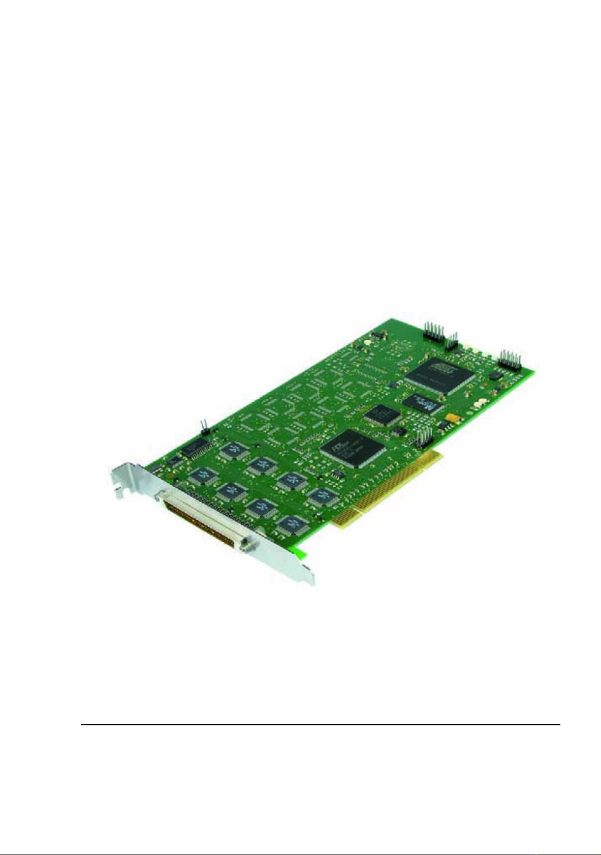
4.4 Details on the Board
Diagram 2: ME-A429 PCI

Manual ME-A429 cPCI/PCI Rev. 1.0E
Meilhaus Electronic Page 13 Hardware Description
4.4.1 Optical control of operation
There are eight LEDs mounted on the PCB. With these LEDs the user
can determine if the PCI/cPCI card works the way it is intended to do.
If LED5...LED8 are glowing, then all necessary voltages should be
present on the board. It is possible that not all LEDs, especially LED5
and LED6 are mounted for all versions of the ME-A429/x.
For firmware operations the four LEDs on the right are of bigger interest.
From top to bottom:
1. LED1 (green) glows when all initializations in the firmware have
been executed successfully. The ME-A429 is ready for interaction
with the host.
2. LED2 (green) shows the actual mode the firmware is in. This may
either be “config mode”, the LED is off or “run mode”, the LED
is on.
3. LED3 (red) is currently related to no functionality.
4. LED4 (red) shows an error on the receiver side of some channel.
This means, that the queue in the DPR is full and the controller is
trying to send another ARINC429 data word to the host.
The two error LEDs (LED3 and LED4) will be turned on as soon as the
first error occurs and they stay on until the moment a new “enter run
mode”-command is present in the command queue.
NOTE: It is possible that you will get a RX error if you stop the applica-
tion running on the host and another ARINC429 bus unit is still active
and sending data
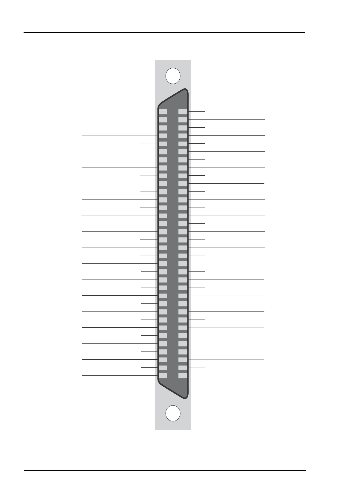
4.5 Pin Assignment
Diagram 3: Frontview of the connector on the card
On the ME-A429 a 68-pin MDR Connector (SCSI-2 layout compati-
ble) is mounted. The various versions of the ME-A429 have different
pinouts.
342
6835
1

Rev. 1.0E Manual ME-A429 cPCI/PCI
Hardware Description Page 14 Meilhaus Electronic
4.5.1 ME-A429/4
Pin Description Pin Description
1open 35 AOUT_00
2open 36 BOUT_00
3AIN_00 37 open
4BIN_00 38 open
5open 39 BOUT_01
6open 40 AOUT_01
7open 41 open
8open 42 open
9open 43 open
10 open 44 open
11 open 45 open
12 open 46 open
13 open 47 open
14 open 48 open
15 AIN_01 49 open
16 BIN_01 50 open
17 open 51 open
18 open 52 open
19 open 53 open
20 open 54 open
21 open 55 open
22 open 56 open
23 open 57 open
24 open 58 open
25 BOUT_02 59 open
26 AOUT_02 60 open
27 AIN_02 61 open
28 BIN_02 62 open
29 BOUT_03 63 open
30 AOUT_03 64 open
31 open 65 AIN_03
32 open 66 BIN_03
33 GPIO_IN 67 GND
34 GPIO_OUT 68 GND

Manual ME-A429 cPCI/PCI Rev. 1.0E
Meilhaus Electronic Page 15 Hardware Description
4.5.2 ME-A429/8
Pin Description Pin Description
1BOUT_07 35 AOUT_00
2AOUT_07 36 BOUT_00
3AIN_00 37 AIN_07
4BIN_00 38 BIN_07
5open 39 BOUT_01
6open 40 AOUT_01
7open 41 open
8open 42 open
9open 43 open
10 open 44 open
11 open 45 open
12 open 46 open
13 BOUT_06 47 open
14 AOUT_06 48 open
15 AIN_01 49 AIN_06
16 BIN_01 50 BIN_06
17 open 51 open
18 open 52 open
19 open 53 open
20 open 54 open
21 open 55 open
22 open 56 open
23 open 57 open
24 open 58 open
25 BOUT_02 59 BOUT_05
26 AOUT_02 60 AOUT_05
27 AIN_02 61 AIN_05
28 BIN_02 62 BIN_05
29 BOUT_03 63 BOUT_04
30 AOUT_03 64 AOUT_04
31 AIN_04 65 AIN_03
32 BIN_04 66 BIN_03
33 GPIO_IN 67 GND
34 GPIO_OUT 68 GND

Rev. 1.0E Manual ME-A429 cPCI/PCI
Hardware Description Page 16 Meilhaus Electronic
4.5.3 ME-A429/16
Pin Description Pin Description
1BOUT_07 35 AOUT_00
2AOUT_07 36 BOUT_00
3AIN_00 37 AIN_07
4BIN_00 38 BIN_07
5BOUT_08 39 BOUT_01
6BOUT_09 40 AOUT_01
7AOUT_08 41 BOUT_10
8AOUT_09 42 BOUT_11
9BIN_10 43 AOUT_10
10 BIN_09 44 AOUT_11
11 BIN_11 45 BIN_08
12 AIN_08 46 AIN_11
13 BOUT_06 47 AIN_09
14 AOUT_06 48 AIN_10
15 AIN_01 49 AIN_06
16 BIN_01 50 BIN_06
17 BOUT_14 51 BOUT_12
18 BOUT_15 52 BOUT_13
19 AOUT_14 53 AOUT_12
20 AOUT_15 54 AOUT_13
21 BIN_13 55 BIN_15
22 AIN_12 56 BIN_14
23 AIN_13 57 AIN_15
24 BIN_12 58 AIN_14
25 BOUT_02 59 BOUT_05
26 AOUT_02 60 AOUT_05
27 AIN_02 61 AIN_05
28 BIN_02 62 BIN_05
29 BOUT_03 63 BOUT_04
30 AOUT_03 64 AOUT_04
31 AIN_04 65 AIN_03
32 BIN_04 66 BIN_03
33 GPIO_IN 67 GND
34 GPIO_OUT 68 GND

Manual ME-A429 cPCI/PCI Rev. 1.0E
Meilhaus Electronic Page 17 Specifications
Appendix
A Specifications
PC interface PCI connector rev 2.1, 32-bit, capable of 3.3V and 5V signaling
environment
Form factor CompactPCI or PCI PC Board
Memory 8kByte Dual Port RAM
Connector 68-pin MDR (SCSI-2 compatible)
ARINC429 Controller HI3585
Number of RX channels 4, 8 or 16
Number of TX channels 4, 8 or 16
Transfer rates 12.5 or 100kBaud
Power supply 5V (±5%) max. 750mA via the PCI interface
Temperature (operational) 0…55°C
Temperature (storage) -10…75°C
Relative humidity 5…95%
Rev. 1.0E Manual ME-A429 cPCI/PCI
Pinout Page 18 Meilhaus Electronic
BPinout
Diagram 4: Pinout of ME-A429/16 with 16 channels
34
32
30
28
26
24
22
20
18
16
14
12
10
8
6
4
2
GPIO_OUT
BIN_04
AOUT_03
BIN_02
AOUT_02
BIN_12
AIN_12
AOUT_15
BOUT_15
BIN_01
AOUT_06
AIN_08
BIN_09
AOUT_09
BOUT_09
BIN_00
AOUT_07
GND
BIN_03
AOUT_04
BIN_05
AOUT_05
AIN_14
BIN_14
AOUT_13
BOUT_13
BIN_06
AIN_10
AIN_11
AOUT_11
BOUT_11
AOUT_01
BIN_07
BOUT_00
GND
AIN_03
BOUT_04
AIN_05
BOUT_05
AIN_15
BIN_15
AOUT_12
BOUT_12
AIN_06
AIN_09
BIN_08
AOUT_10
BOUT_10
BOUT_01
AIN_07
AOUT_00
GPIO_IN
AIN_04
BOUT_03
AIN_02
BOUT_02
AIN_13
BIN_13
AOUT_14
BOUT_14
AIN_01
BOUT_06
BIN_11
BIN_10
AOUT_08
BOUT_08
AIN_00
BOUT_07
68
66
64
62
60
58
56
54
52
50
48
46
44
42
40
38
36
67
65
63
61
59
57
55
53
51
49
47
45
43
41
39
37
35
33
31
29
27
25
23
21
19
17
15
13
11
9
7
5
3
1

Manual ME-A429 cPCI/PCI Rev. 1.0E
Meilhaus Electronic Page 19 Accessories
C Accessories
Fitting accessories for ME-A429
• 68 poles connector compatible to National Instruments’ cable
(NI SHC-68)
• Breakout box (NI SCB-68)

Rev. 1.0E Manual ME-A429 cPCI/PCI
Technical Questions Page 20 Meilhaus Electronic
D Technical Questions
D1 Hotline
If you should have any technical questions or problems that can be put
down to your Meilhaus device, please send a fax to our hotline:
Fax hotline: + 49 (0) 89/89 01 66 28
eMail: [email protected]
Please give a full description of the problems and as much information as
possible, including operating system information.
D2 Service address
If a technical error should occur with your device please contact us at the
following address:
Meilhaus Electronic GmbH
Service Department
Fischerstraße 2
D-82178 Puchheim/Germany
If you want to send back a device to be repaired it is strictly necessary to
request for a RMA number and to follow the notes to deal with the RMA
process. Please attach a detailed error description of the problem, inclu-
ding information about operating system and application software!
D3 Driver Update
The current driver versions for Meilhaus devices and our manuals in PDF
format are available under www.meilhaus.com.
Table of contents
Other Meilhaus Electronic PCI Card manuals


Popular PCI Card manuals by other brands


TRENDnet
TRENDnet TEW-403PIplus Specifications

SMC Networks
SMC Networks WPCIES-N datasheet

SMC Networks
SMC Networks WPCI-N - annexe 1 Quick installation guide

ZyXEL Communications
ZyXEL Communications WLAN PCI Card IEEE802.11b user manual

HighPoint
HighPoint RocketU 1344C Quick installation guide

Belkin
Belkin F5U220 user manual