Meilhaus Electronic ME Series User manual
Meilhaus Electronic Manual
ME-1600 Series
(PCI- and CompactPCI-Versions)
12-bit D/A-Conversion Board with up to
16 Channels and optional Current Outputs

Imprint
Manual ME-1600 PCI/cCI Series
Revision 3.0E
Revised: 2019-11-27
Meilhaus Electronic GmbH
Am Sonnenlicht 2
D-82239 Alling bei München
Germany
www.meilhaus.de
© Copyright 2019 Meilhaus Electronic GmbH
All rights reserved. No part of this publication may be reproduced
or distributed in any form whether photocopied, printed, put on mi-
crofilm or be stored in any electronic media without the expressed
written consent of Meilhaus Electronic GmbH.
Important note:
The information contained in this manual has been reviewed with
great care and is believed to be complete and accurate. Meilhaus
Electronic assumes no responsibility for its use, any infringements
of patents or other rights of third parties which may result from
use of this manual or the product. Meilhaus Electronic assumes no
responsibility for any problems or damage which may result from
errors or omissions. Specifications and instructions are subject to
change without notice.
Note the Meilhaus Electronic general terms of business:
www.meilhaus.de/en/infos/my-shop/tob/
All trademarks acknowledged. All trademarks are property of their
respective owners.

Content
1Introduction...........................................................5
1.1 Important Notes ............................................................... 5
1.1.1 Use in Accordance with the Requirements ....................... 5
1.1.2 Improper Application ...................................................... 6
1.1.3 Unforseeable Misapplications .......................................... 6
1.1.4 Warning........................................................................ 6
1.2 Package Contents ............................................................. 7
1.3 Features .......................................................................... 7
1.4 System Requirements ....................................................... 8
1.5 Software Support ............................................................. 8
2Starting up............................................................9
2.1 Software Installation ......................................................... 9
2.3 Test Program.................................................................... 9
3Hardware ............................................................10
3.1 Block Diagram ................................................................. 10
3.2 D/A Section .................................................................... 11
3.2.1 Output Ranges ............................................................ 11
3.2.2 Voltage Outputs .......................................................... 12
3.2.3 Current Outputs ......................................................... 12
4Programming .......................................................14
4.1 D/A Section .................................................................... 14
4.1.1 Single Value Output ..................................................... 15
4.1.1.1 Operation Mode “Transparent” ........................... 15
4.1.1.2 Operation Mode “Synchronous”........................... 15
4.1.1.3 Current Output ................................................. 16
5Appendix .............................................................17
ASpecifications ........................................................................ 17
BPinout ................................................................................... 19
B1 Pinout D-Sub Connector ................................................. 19
CAccessories........................................................................... 20

1 Introduction
Valued customer,
Thank you for purchasing this device from Meilhaus Electronic. You
have chosen an innovative high-technology product that left our
premises in a fully functional and new condition.
Please take the time to carefully examine the contents of the pack-
age for any loss or damage that may have occurred during shipping.
If there are any items missing or if an item is damaged, please con-
tact us immediately.
Before installing the board in your computer, we recommend you
read this manual carefully, especially the chapter describing board
installation.
The descriptions in this manual concern PCI, PCI-Express and Com-
pactPCI-versions of the ME-1600 series, if not otherwise noted.
1.1 Important Notes
1.1.1 Use in Accordance with the Requirements
The PC boards of the ME series are designed for acquisition and
output of analog and digital signals with a PC. Depending on type
install the models of the ME series into:
a free PCI slot (PCI versions) or
a free PCI-Express slot (PCIe versions) or
a free CompactPCI slot (3 HE cPCI versions)
For information on how to install a plug-in board or connect a USB
device, please read the manual of your PC.
Please note the instructions and specifications as presented in
this manual (Appendix, A Specifications):
Please ensure sufficient heat dissipation for the board within
the PC housing.
All unused inputs should be connected to the ground reference
of the appropriate functional section. This avoids cross talk be-
tween the input lines.

The opto-isolated inputs and outputs achieve an electrical isola-
tion of the application relative to PC ground.
Note that the computer must be powered up prior to connect-
ing signals by the external wiring of the board.
As a basic principle, all connections to the board should only be
made or removed in a powered-down state of all components.
Ensure that no static discharge occurs while handling the
board or while connecting/disconnecting the external cable.
Ensure that the connection cable is properly connected. It
must be seated firmly on the D-Sub connector and must be
tightened with both screws, otherwise proper operation of the
board cannot be guaranteed.
1.1.2 Improper Application
PC plug-in boards for the PCI, PCI-Express or CompactPCI bus may
not be taken into operation outside of the PC. Never connect the
devices with voltage-carrying parts, especially not with mains volt-
age. As power supply for the USB models only an authorized power
adaptor may be used.
Make sure that no contact with voltage-carrying parts can happen
by the external wiring of the device. As a basic principle, all connec-
tions should only be made or removed in a powered-down state.
1.1.3 Unforseeable Misapplications
The device is not suitable to be used as a children’s toy, in the
household or under unfavourable environmental conditions (e.g. in
the open). Appropriate precautions to avoid any unforeseeable mis-
application must be taken by the user.
1.1.4 Warning
The device was developed and produced in accordance to the EMC
low-voltage directive 73/23/EWG. When putting the device into op-
eration, especially with voltages greater than 42 V, please follow
the appropriate standards, installation instructions and national
safety standards. Meilhaus Electronic GmbH assumes no responsi-
bility for damage in case of faulty installation, operation or handling.
1.2 Package Contents
We take great care to ensure your delivery is complete. Nonethe-
less, please check the list enclosed to verify the contents of your
delivery. You should find included:
D/A conversion board of the ME-1600 family for
PCI- or CompactPCI-bus.
Manual in PDF format on CD-ROM (optional as printed version).
Driver software on CD-ROM.
78-pin D-Sub male connector.
1.3 Features
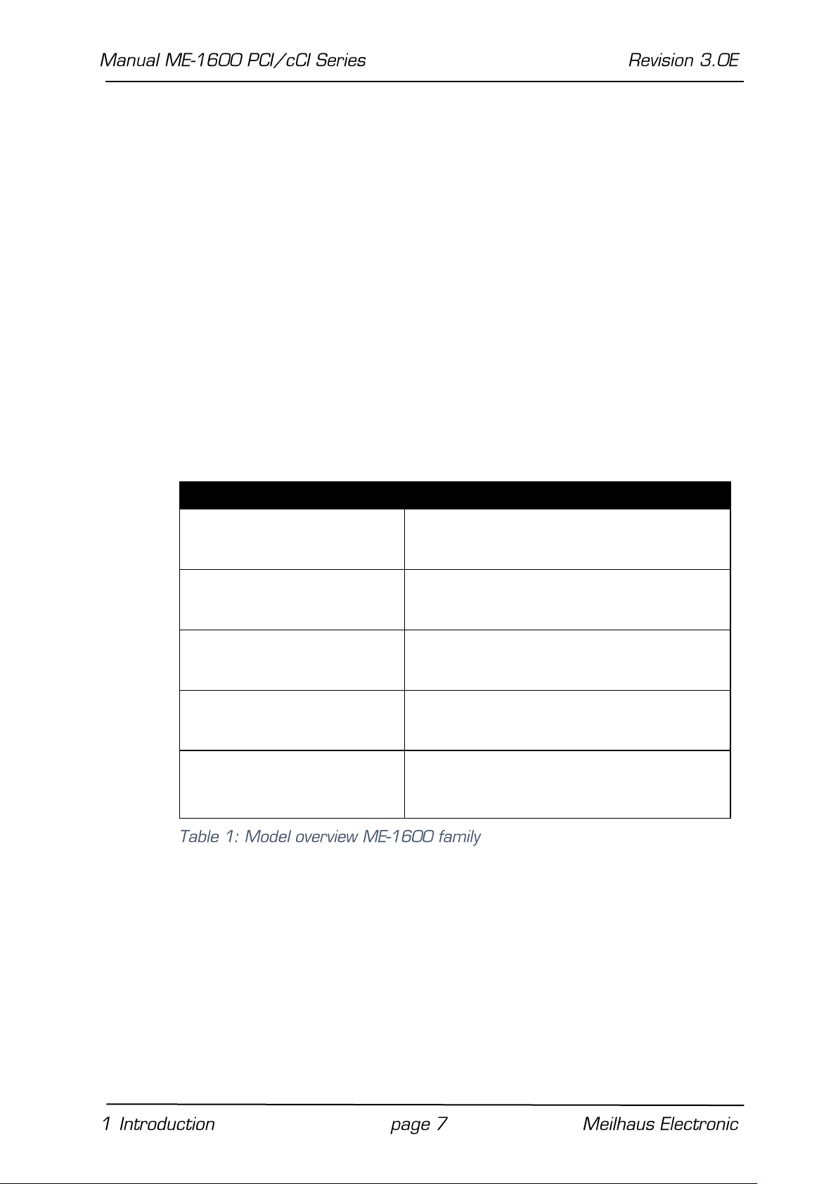
Model Overview
Model
D/A
Channels
ME-1600/4U PCI
ME-1600/4U cPCI
4 voltage outputs
ME-1600/8U PCI
ME-1600/8U cPCI
8 voltage outputs
ME-1600/12U PCI
ME-1600/12U cPCI
12 voltage outputs
ME-1600/16U PCI
ME-1600/16U cPCI
16 voltage outputs
ME-1600/16U8I PCI
ME-1600/16U8I cPCI
16 voltage outputs, of which 8 channels
can be used for current output at the
same time
The boards of the ME-1600 family have 4, 8, 12 or 16 D/A chan-
nels depending on the model. Thereby each 4 channels are located
in one 12-bit D/A converter component (DAC). Every voltage output
can be driven independently of one another in the output ranges
0…10 V or ±10 V.
Optional: From the 16 channels of the board up to 8 channels can
also be used for current output. At the same time the correspond-
ing voltage outputs can be used with a voltage proportional to the

adjusted current. The current outputs can be driven in the output
ranges 0…20 mA or 4…20 mA and are short-circuit proof.
1.4 System Requirements
The ME-series may be installed into any PC (Intel® Pentium® pro-
cessor) with a free standard PCI-, PCI-Express- resp. CompactPCI-
slot (32 bit, 33 MHz, 5 V). The board is supported by the Meilhaus
Electronic Intelligent Driver System (ME-iDS).
1.5 Software Support
The ME-series is supported by the Meilhaus Electronic Intelligent
Driver System (ME-iDS). The ME-iDS is a unique driver system cov-
ering different devices and operating systems. It supports Win-
dows 2000/XP/Vista and Windows 7, 8.1, 10 and contains a uni-
versal function library (API) for all common programming languages.
A detailed description of the functions can be found in the ME-iDS
manual on the CD/DVD enclosed.
Please also note the corresponding README-files.

2 Starting up
Please read your computer’s instruction manual on how to install
new hardware components before installing the board.
2.1 Software Installation
Installation under Windows
The following basic procedure should be used:
If you have received the driver software as an archive file, please
unpack the software before installing the board. First choose a di-
rectory on your computer (e.g. C:\Temp\Meilhaus\ME-iDS).
Use the Meilhaus Electronic Intelligent Driver System (ME-iDS) for
programming your new data acquisition hardware. For installation
and operation of the driver system, please follow the documenta-
tion in electronic form included with the software package.
2.3 Test Program
For simple testing of the board use the corresponding test pro-
gram provided with the ME-iDS.
3 Hardware
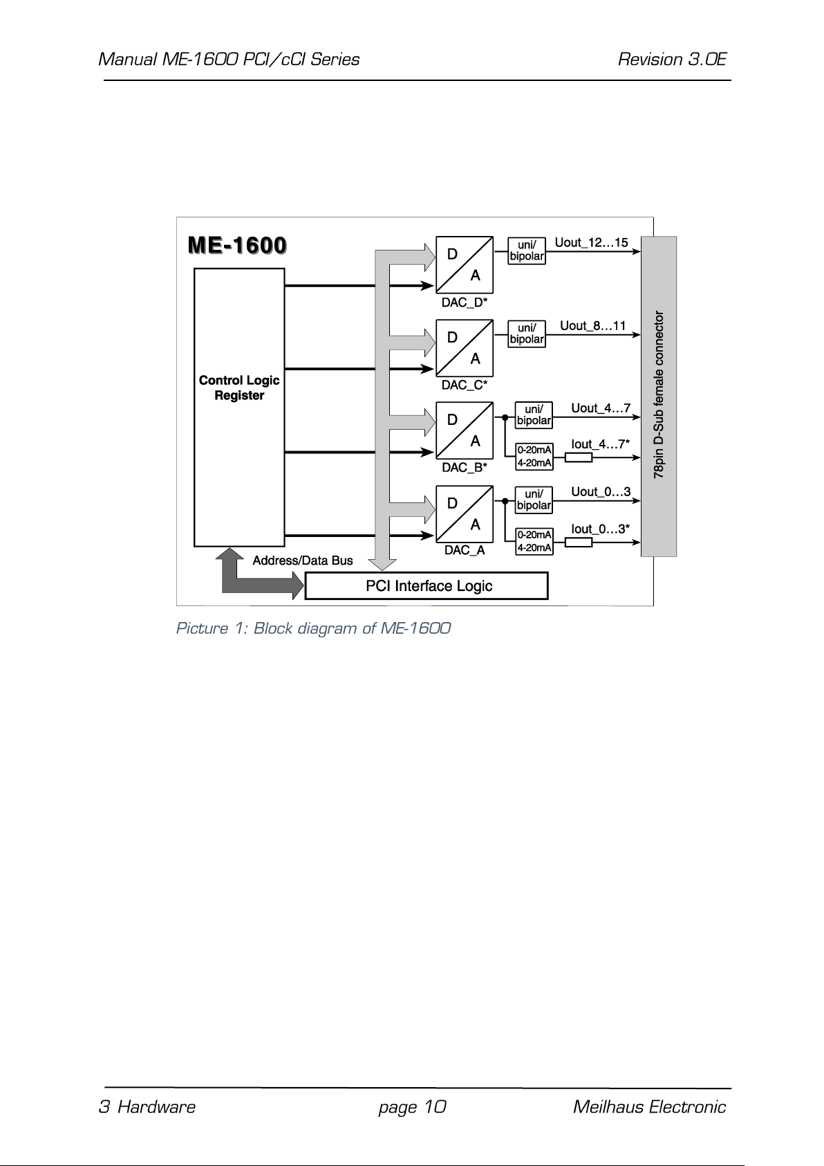
3.1 Block Diagram
* Depending on the version not all functional groups included in the
block diagram above are available:
ME-1600/4U: 4 voltage outputs (UOUT _0…3).
ME-1600/8U: 8 voltage outputs (UOUT _0…7).
ME-1600/12U: 12 voltage outputs (UOUT _0…11).
ME-1600/16U: 16 voltage outputs (UOUT _0…15).
ME-1600/16U8I: 16 voltage outputs (UOUT_0…15) and
8 current outputs (IOUT_0…7)
3.2 D/A Section
The DAC-boards of the ME-1600 family can output voltages
(0…10 V, ±10 V) and optionally currents (0…20 mA, 4…20 mA).
Each 4 channels are integrated into one 12-bit DAC-component
(see also chapter programming from page 14 up).
Attention:
To guarantee a defined power-up condition please start your host
computer first and do not power-up your external wiring until the
driver started.
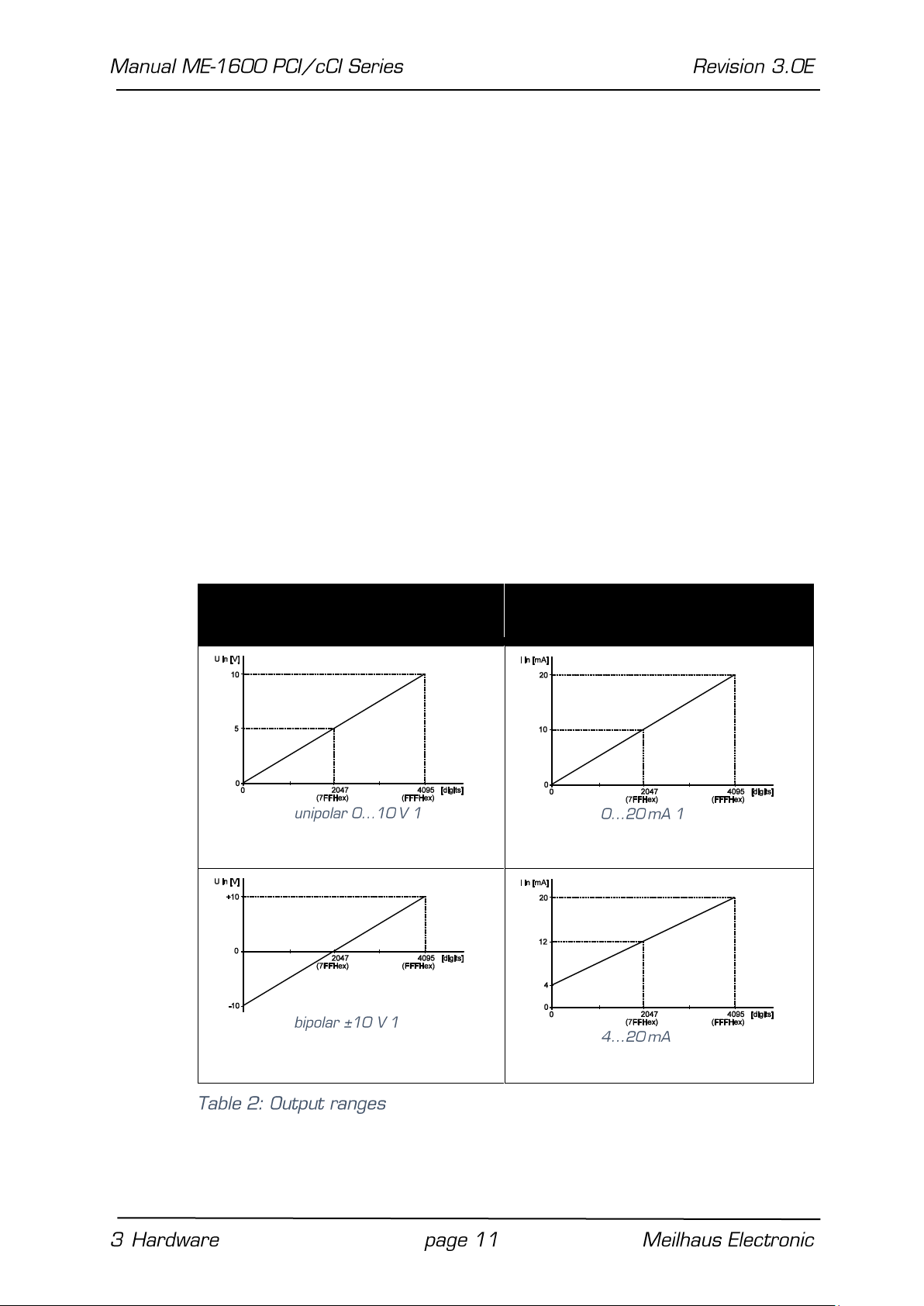
3.2.1 Output Ranges
The output ranges can be chosen separately for each channel. Volt-
age and current ranges can be used independently from one an-
other:
Voltage Ranges
Current Ranges (optional)
Note: After changing the output range (e.g. from 0…10 V to
±10 V) the value written to the output register of the DAC will be
newly interpreted and output immediately.
For the pin configuration of the 78-pin female D-Sub see „Pinout of
the 78-pin D-Sub female connector” on page 19). Pins which are
assigned to function groups not provided are not connected.
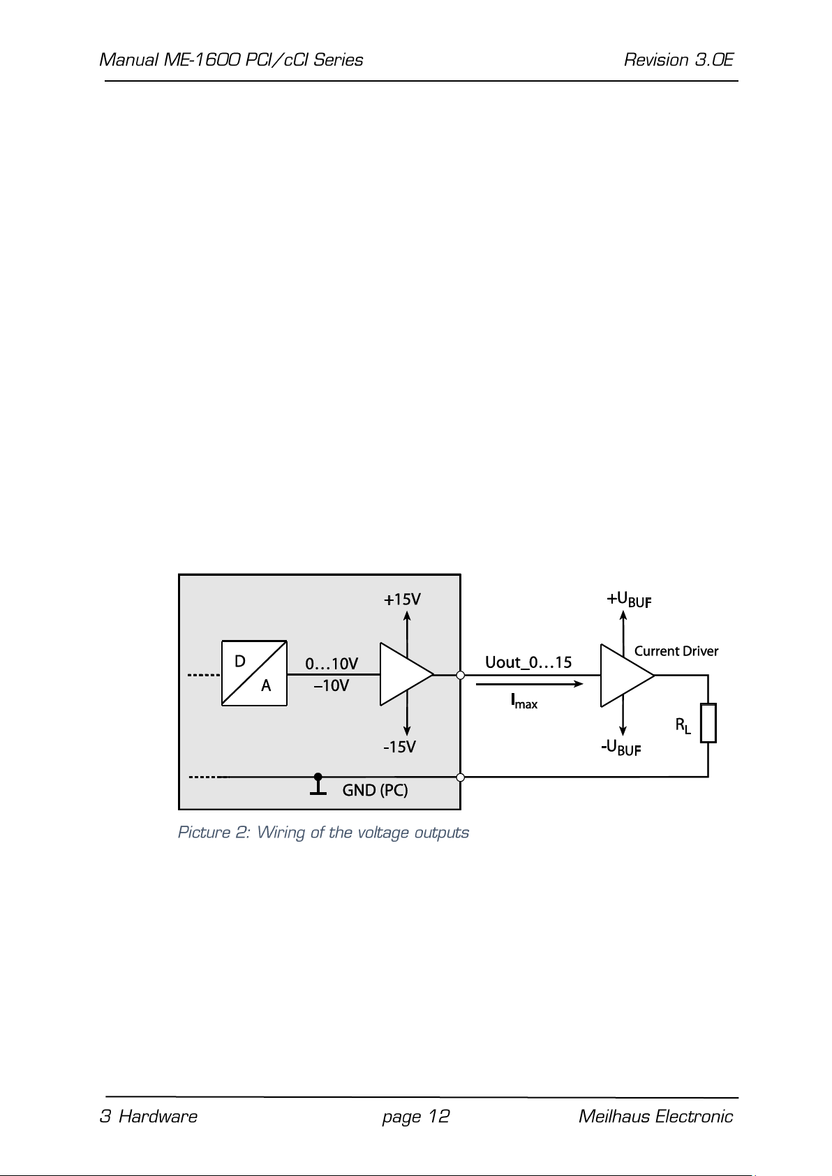
3.2.2 Voltage Outputs
Attention: The total current of all voltage outputs must not ex-
ceed ±32 mA per channel! One single channel must not exceed Imax
= ±20 mA.
If one of the maximum values above should be exceeded we recom-
mend the usage of external drivers. The +5 V supply of the PC
available at the D-Sub connector can be used to supply a DC/ DC
converter sourcing the necessary symmetrical voltage of ±UBUF =
±15 V.
3.2.3 Current Outputs
The current outputs of the ME-1600 are realized as voltage con-
trolled constant-current-sources. The outputs are short-circuit
proof.
Note that the driver components are warming up significantly if a
short-circuit happens. Ensure a sufficient heat flow and take into
account an appropriate protection against contact.

For operation of the constant-current-source an external voltage
supply Uext is necessary, depending on the load resistor RLand the
current ILto be kept constant. An extra charge of voltage of UOPV =
5 V for the output circuitry must be taken into account.
Example:
The load resistor RLshould be 1 kΩand the current to be kept con-
stant should be 20 mA. The minimum required voltage supply Uext
results as follows:
Uext ≥ UOP + UL= UOP + (RLx IL)
= 5 V + (1 kΩx 20 mA) = 25 V
Attention: Uext must not exceed. 36 V!

4 Programming
For programming the device please use the Meilhaus Electronic In-
telligent Driver System (ME-iDS) included in your package. The ME-
iDS is a unique driver system covering different devices and operat-
ing systems. It supports Windows 2000 and higher and contains a
universal function library (API) for all common programming lan-
guages (the extent of the current software support can be found in
the readme files of the ME-iDS).
A detailed description of the functions can be found in the ME-iDS
manual (see CD/DVD enclosed or online:
www.meilhaus.de/download/ME-iDS.
Further details regarding the assignment of the subdevices and de-
vice specific arguments can be found in the help file (help file format
under Windows, *.chm) which can be accessed via the „ME-iDS
Control Center“ in the info area of the task bar (as a rule in the
lower right corner of the screen) or via the Windows start menu.
If you do not want to program your board with the ME-iDS you find
the last revision of the old function reference in the ME-1600 man-
ual Rev. 2.0 (see: www.meilhaus.com/download/ME-1600). Please
note, that we cannot support this driver anymore.
4.1 D/A Section
In the Meilhaus Intelligent Driver System (ME-iDS) each D/A chan-
nel is regarded as a subdevice of type ME_TYPE_AO, subtype
ME_SUBTYPE_SINGLE. The following table shows the assignment of
subdevices:
DAC
Subdevice
Output
Models
DAC_A
subdevice 0…3
(ME_TYPE_AO)
UOUT 0…3
all models
IOUT 0…3
only ME-1600/16U8I
DAC_B
subdevice 4…7
(ME_TYPE_AO)
UOUT 4…7
ME-1600/8U,
ME-1600/12U,
ME-1600/16U,
ME-1600/16U8I

IOUT 4…7
only ME-1600/16U8I
DAC_C
subdevice 8…11
(ME_TYPE_AO)
UOUT 8…11
ME-1600/12U,
ME-1600/16U,
ME-1600/16U8I
DAC_D
subdevice 12…15
(ME_TYPE_AO)
UOUT 12…15
ME-1600/16U,
ME-1600/16U8I
For wiring of the analog outputs please read chapter 3.2 on page
11.
4.1.1 Single Value Output
The analog output of a value (voltage/current) is done in operation
mode „Single“. Each D/A channel is accessed as a subdevice of
type ME_TYPE_AO, subtype ME_SUBTYPE_SINGLE. Note the order
of operation as described in the ME-iDS manual. The following pa-
rameters can be configured by the functions and
Subdevice: see table 3.
Channel number: always „0“ (channel = subdevice).
Output voltage range: 0…10 V, ±10 V,
ME-1600/16U8I additionally: 0…20 mA, 4…20 mA.
Trigger channel: By the parameter <TrigChan> you can choose
between the operation modes „Transparent“ and “Synchro-
nous“ for each subdevice (see chap. 4.1.1.1 and 4.1.1.2).
Trigger type: Software trigger (ME_TRIG_TYPE_SW).
Trigger edge: not relevant (see trigger type).
4.1.1.1 Operation Mode “Transparent”
The operation mode „Transparent“ can be configured individually for
each channel (subdevice). Doing this pass the constant
ME_TRIG_CHAN_DEFAULT in parameter <TrigChan> of the function
. The value passed in parameter <Value> of the
function is output immediately after calling the function.
Also applicable for current output see 4.1.1.3 Current Output.
4.1.1.2 Operation Mode “Synchronous”
The operation mode „Synchronous“ can be configured individually for
each channel (subdevice). Appropriately at least two channels
should be included in the synchronous output. Configuration of the
single channels is done by repeatedly calling the functions
and . Pass the constant
ME_TRIG_CHAN_SYNCHRONOUS in parameter <TrigChan> of the
function to prepare a channel for synchronous
output. For the last channel to be included in the synchronous out-
put you must pass the constant ME_IO_SINGLE_TYPE_ TRIG_SYN-
CHRONOUS in parameter <Flags> of the list <SingleList> in
the function . By this function call the synchronous out-
put starts. Also applicable for current output see 4.1.1.3 Cur-
rent Output.
4.1.1.3 Current Output
On model ME-1600/16U8I from the 16 channels of the board up to
8 channels can also be used for current output. The current out-
puts are lead to separate pins (Iout_0…7) of the 78-pin D-Sub con-
nector. This enables you to use the voltage outputs with a voltage
proportional to the adjusted current. The current channels are en-
abled automatically when a current range in parameter <Single-
Config> of the function is passed. Determine the
current range wanted by the function or
pass one of the following values:
„2“ ➝0…20 mA
„3“ ➝4…20 mA
5 Appendix
A Specifications
PCI-Interface
Bus system
Standard PCI (32 bit, 33 MHz, 5 V);
(depends on model)
CompactPCI (32 bit, 33 MHz, 5 V)
Plug&Play-operation
resources are assigned automatically
Voltage Outputs
Number
4, 8, 12 or 16 (depends on version)
D/A converter
Quad type, Burr-Brown DAC7624U
Resolution
12 bit
Output ranges
0…10 V, ±10 V
Total output current
max. ±32 mA (all channels)
Output current per channel
max. ±20 mA
Operation modes
synchronous or transparent
Gain error
typ. ±3 LSB
Zero error (bipolar)
max. ±3 LSB
Linearity error (DAC
max. ±2 LSB
Settling time (DAC)
max. 10 µs (-10 V →+10 V)
Current Outputs (only ME-1600/16U8I)
Number
8
D/A converter
Burr-Brown INA132
Output ranges
0…20 mA, 4…20 mA
Output power per channel
max. 0.65 V
(for Uext= 36 V and RL=1.5 kΩ)
short circuit: 0.7 W
Accuracy (0…20 mA)
max. 0.45 %
Accuracy (4…20 mA
max. 0.375 %
Settling time (DAC)
max. 0.5 µs (full scale)
General Information
Power consumption at
+5 V
ME-1600/16U: typ. 1.5 A
VCC-loading at the D-Sub
connector
approx. 2 A (depends on PC power supply)
Physical size
ME-1600 PCI: 174 mm x 98 mm
(without mounting bracket and connector )
ME-1600 cPCI: 3-U-CompactPCI board
Connectors
78-pin D-Sub female connector
Operating temperature
0…70 °C
Storage temperature
-40…100 °C
Relative humidity
20…55 % (non-condensing)
CE-Certification
EMC Directive
89/336/EMC
Emission
EN55022
Noise immunity
EN50082-2

B Pinout
B1 Pinout D-Sub Connector
*Depending on the version not all pins of the 78-pin D-Sub con-
nector are available.

This manual suits for next models
13
Table of contents
Other Meilhaus Electronic PCI Card manuals


Popular PCI Card manuals by other brands


Addonics Technologies
Addonics Technologies ADSA3GPX8-ML user guide

ASTEK
ASTEK Quantum Parametrics SAS2 user guide

Acces I/O products
Acces I/O products PCI-IDO-48A user manual

Belkin
Belkin F5U219 user manual

OpenVox
OpenVox B400P user manual

SIIG
SIIG DP SuperSpeed USB 3.0 2-Port PCIe i/e Quick installation guide