Meilhaus Electronic ME-5001 User manual

Meilhaus Electronic Manual
ME-5001 3.0E
Plug-on Board for ME-5000 Series
with up to 48 Digital I/Os
(alternatively: Frequency Measurement and Pulse Generator)

Imprint
Manual ME-5001
Revision 3.0E
Revised: 2018-05-08
Meilhaus Electronic GmbH
Am Sonnenlicht 2
D-82239 Alling bei München
Germany
www.meilhaus.de
© Copyright 2018 Meilhaus Electronic GmbH
All rights reserved. No part of this publication may be reproduced
or distributed in any form whether photocopied, printed, put on mi-
crofilm or be stored in any electronic media without the expressed
written consent of Meilhaus Electronic GmbH.
Important note:
The information contained in this manual has been reviewed with
great care and is believed to be complete and accurate. Meilhaus
Electronic assumes no responsibility for its use, any infringements
of patents or other rights of third parties which may result from
use of this manual or the product. Meilhaus Electronic assumes no
responsibility for any problems or damage which may result from
errors or omissions. Specifications and instructions are subject to
change without notice.
Note the Meilhaus Electronic general terms of business:
www.meilhaus.de/en/infos/my-shop/tob/
All trademarks acknowledged. All trademarks are property of their
respective owners.

Content
1Introduction...........................................................5
1.1 Important Notes ............................................................... 5
1.1.1 Use in Accordance with the Requirements ....................... 5
1.1.2 Improper Application ...................................................... 6
1.1.3 Unforeseeable Misapplications ........................................ 6
1.2 Package Contents ............................................................. 6
1.3 Features .......................................................................... 7
1.4 System Requirements ....................................................... 8
1.5 Software Support ............................................................. 8
2Starting up............................................................9
2.1 Software Installation ......................................................... 9
2.2 Test Program.................................................................... 9
2.3 Fitting the Plug-on Boards ................................................. 9
3Hardware ............................................................11
3.1 Block Diagram ................................................................. 11
3.2 ME-5001 cPCI/PCIe ......................................................... 12
3.3 Digital Input/Output ......................................................... 12
3.3.1 Digital Inputs .............................................................. 13
3.3.2 Digital Outputs............................................................ 13
3.3.3 External Trigger........................................................... 14
3.4 Frequency Input/Output ................................................... 14
3.5 External Interrupt ........................................................... 15
3.6. Additional Functions ........................................................ 15
3.6.1 Termination ................................................................. 15
3.6.2 Logic Level Matching.................................................... 15
4Programming .......................................................16
4.1 Single Operation Mode ..................................................... 18
4.1.1 Digital Input/Output ..................................................... 18
4.1.2 Frequency Input/Output................................................ 18
4.1.2.1 Frequency Measurement .................................... 20
4.1.2.2 Pulse Generator ................................................ 20
4.2 Interrupt Operation ......................................................... 21
4.2.1 Bit-Pattern Change...................................................... 21
5Appendix .............................................................23
ASpecification .......................................................................... 23
BPinout ................................................................................... 26
B1 25-pin D-Sub (ST1)................................................................. 27
B2 Additional Sockets (ST2/ST3)................................................... 28
CAccessories........................................................................... 30
DTechnical Questions ................................................................ 31
D1 Hotline ........................................................................... 31
EIndex ..................................................................................... 32

1 Introduction
Valued customer,
Thank you for purchasing this device from Meilhaus Electronic. You
have chosen an innovative high-technology product that left our
premises in a fully functional and new condition.
Please take the time to carefully examine the contents of the pack-
age for any loss or damage that may have occurred during shipping.
If there are any items missing or if an item is damaged, please con-
tact us immediately.
Before installing the board in your computer, we recommend you
read this manual carefully, especially the chapter describing board
installation.
1.1 Important Notes
1.1.1 Use in Accordance with the Requirements
The plug-on boards of the ME-5000 series require a base board of
the ME-5000 series and will be plugged onto these and extend the
functionality of the base boards. Depending on the PC platform the
plug-on board additionally needs:
a free PCI-Express slot (PCIe) or
a free CompactPCI slot (cPCI)
however, without using the PCI slot connector.
Please follow the instructions of chapter 2.3 on page 9 of this doc-
ument and the manual of your computer for the procedure when
fitting additional hardware components.
Please follow the notes and the specifications starting on page 23:
Ensure sufficient heat dissipation for the board within the PC
housing.
All unused inputs should be connected to the ground reference
of the appropriate functional section. This avoids cross talk be-
tween the input lines.
When using the configuration „pulse generator“ (FO) unused
output pins should not be connected.

Note that the computer must be powered up, prior connecting
signals by the external wiring of the board.
As a basic principle, all connections to the board should only be
made or removed in a powered down state of all components.
Ensure that no static discharge occurs when handling the
board or when connecting/disconnecting the external cable.
Ensure that the connecting cable is properly connected. It
must be seated firmly on the D-Sub connector and must be
tightened with the both screws, otherwise proper operation of
the board cannot be guaranteed!
1.1.2 Improper Application
PC plug-in boards for the PCI-, PCI-Express- or CompactPCI-bus
may not be taken into operation outside of the PC. Never connect
the devices with voltage-carrying parts, especially not with mains
voltage. As power supply for the USB models only an authorized
power adaptor may be used.
Make sure that no contact with voltage-carrying parts can happen
by the external wiring of the device. As a basic principle, all connec-
tions should only be made or removed in a powered-down state.
1.1.3 Unforeseeable Misapplications
The device is not suitable to be used as a children’s toy, in the
household or under unfavourable environmental conditions (e.g. in
the open). Appropriate precautions to avoid any unforeseeable mis-
application must be taken by the user.
1.2 Package Contents
We take great care to ensure your delivery is complete. Nonethe-
less, please check the list enclosed to verify the contents of your
delivery. You should find included:
48-bit digital-I/O board used as a plug-on board for the base
boards of the ME-5000 series.
Manual in PDF format on CD/DVD.
Driver software on CD/DVD.
25-pin D-Sub mating connector.

Note: For connecting the digital I/Os of subdevice 2 up to 5 one
resp. two optional mounting brackets are necessary. Use type ME-
AK-D25F/S for PCI-Express slots resp. ME-AK-D25F/S (cPCI) for
Compact.
1.3 Features
The plug-on board of type ME-5001is a 48-bit digital-I/O board with
bit-pattern detection for the base boards of the ME-5000 series.
You can configure individual subdevices alternatively for frequency
measurement resp. pulse generator on demand (see chapter 4
from page 16).
Overview:
Model
DIO
FIO*
3,3 V/5 V
Termination
ME-5001
(-device 0/1)
2 x 8-bit DIO
8 FI channels/
8 FO channels
4 x 8-bit
4 x 8-bit
(Subdevice 2/3)
2 x 8-bit DIO
-
4 x 8-bit
4 x 8-bit
(Subdevice 4/5)
2 x 8-bit DIO
-
-
-
*Alternative configuration can be activated via ME-iDC.
Digital-I/O ports: The ME-5001 has totally 48-bit-directional
I/Os. The direction can be defined for each of the six 8-bit ports
(subdevice 0..5) by software. After powering up, all the ports
are configured as inputs.
Frequency counter: The concept of the “configurable subde-
vices” allows subdevice 0 to be employed as a frequency coun-
ter. Eight independent channels are available for measuring the
frequency and duty cycle of rectangular signals (max. 5.5 MHz).
Pulse generator: The concept of the “configurable subdevices”
allows subdevice 1 to be employed as a rectangular wave gener-
ator. Eight independent channels are available for the output of
a periodic, rectangular signal at up to 5.5 MHz with a variable
duty cycle.
Signal level 3.3/5 V: The signal level of all the digital inputs/out-
puts and of the control lines can be switched together between

3.3 V and 5 V depending on the external circuitry. The changeo-
ver is made for all the ports of the plug-on board at once using
software.
For optimum signal matching, you are able to activate, via
software, an active 110 Ω termination at the digital inputs/out-
puts of the subdevices 0…3.
Bit pattern detection: The bit-pattern at the digital inputs can
be monitored if required. Depending on the configuration, an in-
terrupt can be triggered in response to a change in the bit-pat-
tern.
The ME-5001 divides the bandwidth for transferring the data from
and to the PC with the respective base card. The actual transfer
rate depends on the activity of the base card and the configuration
of your computer.
Depending on requirements, you can select from the following oper-
ating modes:
Single: In this operating mode, a single value can be read or
written under software control (see chapter 4.1.1 on page 18).
Interrupt: For interrupt handling in the “bit-pattern change”
modes (see chapter 4.2 on page 21).
1.4 System Requirements
The ME-5000 series may be installed into any PC with a free
standard PCI-, PCI-Express resp. CompactPCI-slot (32 bit,
33 MHz, 5 V). The board is supported by the Meilhaus Electronic
Intelligent Driver System (ME-iDS)
1.5 Software Support
The ME-series is supported by the Meilhaus Electronic Intelligent
Driver System (ME-iDS). The ME-iDS is a unique driver system cov-
ering different devices and operating systems. It supports Win-
dows 2000/XP/Vista and Windows 7, 8.1, 10 and contains a uni-
versal function library (API) for all common programming languages.
A detailed description of the functions can be found in the ME-iDS
manual on the CD/DVD enclosed.
Please also note the corresponding README-files.

2 Starting up
Please read your computer’s instruction manual on how to install
new hardware components before installing the board.
2.1 Software Installation
Installation under Windows
The following basic procedure should be used:
If you have received the driver software as an archive file please un-
pack the software before installing the board. First choose a di-
rectory on your computer (e.g. C:\Temp\Meilhaus\ME-iDS).
Use the Meilhaus Electronic Intelligent Driver System (ME-iDS) for
programming your new data acquisition hardware. For installation
and operation of the driver system, please follow the documenta-
tion in electronic form included with the software package.
2.2 Test Program
For simple testing of the board use the corresponding test pro-
gram provided with the ME-iDS.
2.3 Fitting the Plug-on Boards
The boards should be handled with care in order to make sure that
the device is not damaged by electrostatic discharge (ESD), me-
chanical stress or unsuitable current surges. Precautions should
also be taken to avoid an electric shock. Ensure that standard ESD
safety precautions are taken. At least one hand should be
grounded in order to dissipate any static charge.
Observe the following procedure:
1. If the base board is installed, you must first remove it in or-
der to be able to insert the plug-on board. Here you should
observe the procedure as described in the manual for your
PC system.
2. Make sure that electrostatic discharges cannot take place
through the plug-on board or the base board as you plug it
in. Follow the standard ESD safety precautions.
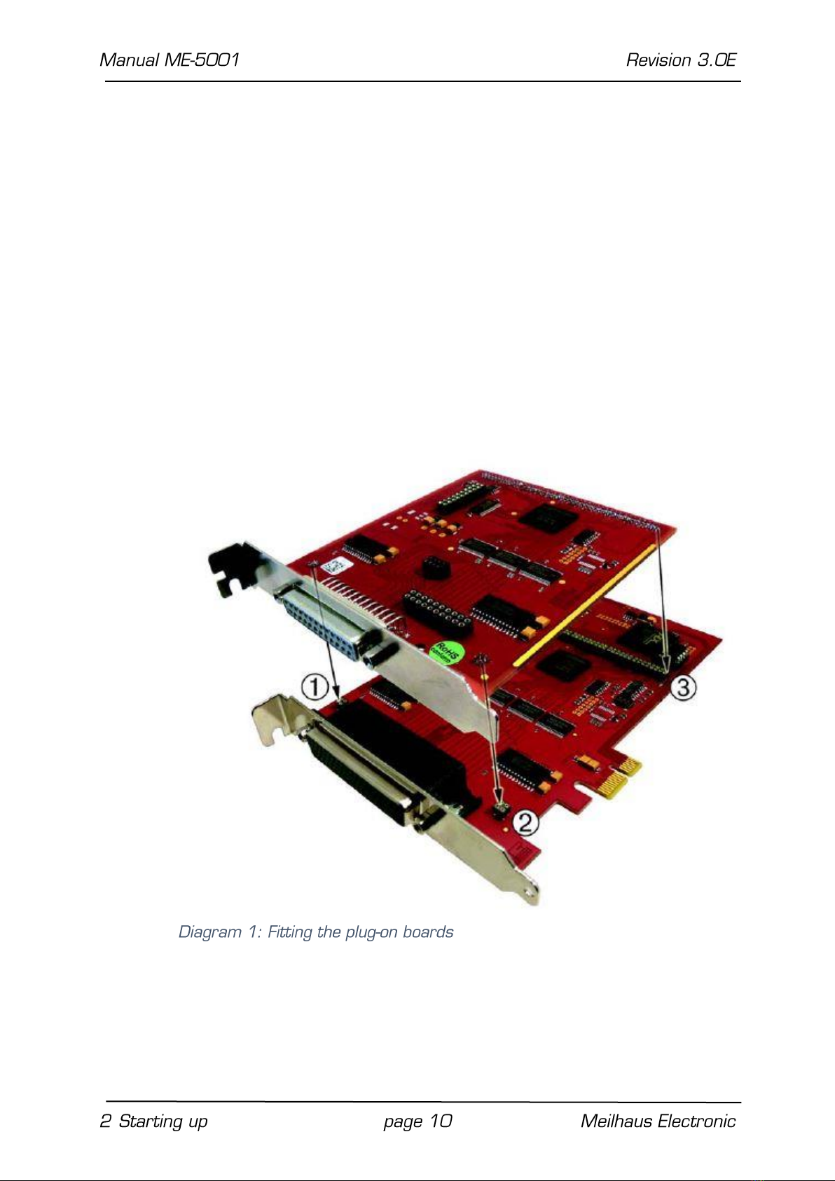
3. Push the plug-on board carefully, and with only a little force,
on to the male connector provided for it (see Diagram 1,
items 1, 2 and 3). Check that the board is fully plugged in.
4. Choose two adjacent slots for the installation. If necessary,
remove an additional mounting bracket for the slot of the
plug-on board.
5. Carefully plug the combination of the base and plug-on board
into the computer.
6. Screw the two slot brackets down firmly.
7. Close the PC system again.


3.2 ME-5001 cPCI/PCIe
3.3 Digital Input/Output
The ME-5001 has a total of six 8-bit digital-I/O ports (subdevice
0..5). In single operation mode, the subdevices can be configured
independently of one another, as input or outputs.
The direction of the ports is defined by software. After powering
up, all the ports are configured as inputs.
Please read chapter 4.1.1 from page 18 for programming the dif-
ferent operating modes.
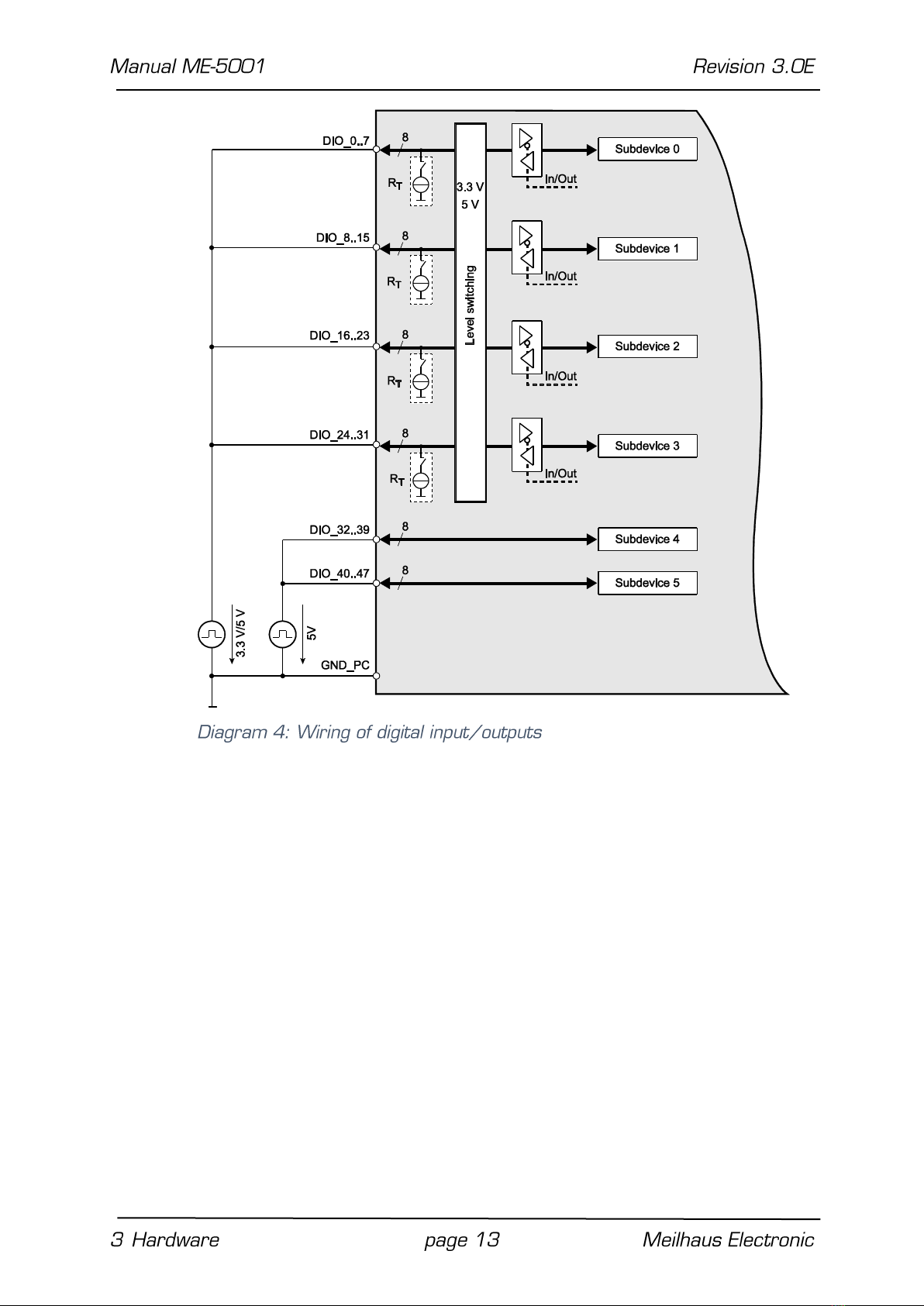
3.3.1 Digital Inputs
When wiring the inputs, note that the voltage level must be ob-
served (see the specifications on page 23) and that a reference to
the PC ground (GND_PC) must be established (see diagram 4).
3.3.2 Digital Outputs
When wiring the outputs, note that the voltage level must be ob-
served (see the specifications on page 23) and that a reference to
the PC ground (GND_PC) must be established (see diagram 4).
IOut = IOL = IOH = 24 mA per pin.

3.3.3 External Trigger
On the ME-5001 no external trigger inputs are available. However
you can monitor the bit-pattern of a digital input port. As soon as
the specified event occurs, an interrupt can be issued and passed
directly to the PC. See chapter 4.2 on page 21.
3.4 Frequency Input/Output
The concept of the “configurable subdevices” of the ME-5000 se-
ries gives you the option of using individual subdevices with an al-
ternative functionality. The associated configuration is carried out
with the ME-iDC configuration tool before your application is called.
The following channels are available:
Frequency measurement (FI=”Frequency Input”):
8 independent inputs for measuring the frequency and duty cy-
cle of rectangular signals (max. 5.5 MHz).
Pulse generator (FO=”Frequency Output”):
8 independent outputs for a periodic rectangular signal at up to
5.5 MHz with a variable duty cycle.
The associated pins are identified as FI_0..7 and FO_0..7 in the
terminal assignment on page 27. After powering up, the pins
FO_0..7 are configured as inputs i.e. in high-impedance state. Not
until the driver has been loaded driver become conductive.
The specifications for the digital-I/O ports apply to the wiring of the
FI/FO lines. A reference to the PC ground (PC_GND) must always
be established. The maximum output current is IOut = IOL = IOH =
24 mA.

The frequency counters and pulse generators are configured by
software. Please read chapter 4.2 on page 21 for programming
the frequency input/output.
3.5 External Interrupt
If required, you can also monitor the bit-pattern of a digital input
port. The “bit-pattern change” mode is available on the ME-5100.
As soon as the specified event occurs, an interrupt is issued and
passed directly to the PC.
The digital inputs/outputs are programmed in the single operating
mode. The interrupt handling is carried out with the func-
tions; see also chapter 4.2 on page 21.
3.6. Additional Functions
You can make the following settings for adapting to your application
regardless of the operating mode.
3.6.1 Termination
For optimum signal matching, you can enable via software, an ac-
tive 110 Ωtermination at the digital inputs/outputs of each port.
The termination circuits are effectively protected against overload
by the combination of current limiting and thermal shutdown (with
automatic return to service).
3.6.2 Logic Level Matching
The signal level of subdevices 0..3 can be switched together be-
tween 3.3 V and 5 V, depending on the external circuitry. The
changeover for the pins DIO_0...31 is made in common by soft-
ware.

4 Programming
For programming the device please use the Meilhaus Electronic In-
telligent Driver System (ME-iDS) included in your package. The ME-
iDS is a unique driver system covering different devices and operat-
ing systems. It supports Windows 2000 and higher and contains a
universal function library (API) for all common programming lan-
guages (the extent of the current software support can be found in
the readme files of the ME-iDS).
A detailed description of the functions can be found in the ME-iDS
manual (see CD/DVD enclosed or online:
www.meilhaus.de/download/ME-iDS.
Further details regarding the assignment of the subdevices and de-
vice specific arguments can be found in the help file (help file format
under Windows, *.chm) which can be accessed via the „ME-iDS
Control Center“ in the info area of the task bar (as a rule in the
lower right corner of the screen) or via the Windows start menu.
The plug-on board of type ME-5001 is a discrete device with six
"subdevices", beginning with the index "0". The functionality of the
subdevices can be specified by the user through selecting a
pre-defined configuration. The desired configuration is loaded into
the board by the ME-iDC configuration tool before your application
starts. Using the standard configuration, (ID 0), the board is ready
to operate immediately. You will find an overview of the currently
available configurations in the following table:
Subdevice Configurations ME-5001
Subdevice Type…
…Subtype
I/Os
ID of the
Configuration
Subdevice 0 (DIO, FI)
Digital input/output
(DIO)
single
8-bit bidirectional
0*
Frequency input (FI)
single
8 channels
1
Subdevice 1 (DIO, FO)
Digital input/output
(DIO)
single
8-bit bidirectional
0*
Frequency output
(FO)
single
8 channels
1

Subdevice 2 (DIO)
Digital input/output
(DIO)
single
8-bit bidirectional
0*
Subdevice 3 (DIO)
Digital input/output
(DIO)
single
8-bit bidirectional
0*
Subdevice 4 (DIO)
Digital input/output
(DIO)
single
8-bit bidirectional
0*
Subdevice 5 DIO)
Digital input/output
(DIO)
single
8-bit bidirectional
0*
*Standard configuration at shipment. The most recently selected
configuration in the ME-iDC is stored in a non-volatile memory on
the board, and is automatically loaded after a restart.
Depending on requirements, you can select from the following oper-
ation modes:
Single: Individual values can be read or written in this operating
mode.
Interrupt: For the interrupt handling in the bit-pattern change
mode (see chapter 4.2.1 starting on page 21.
Operation Mode
Speed
Trigger
Single
single value
input/output via software
Interrupt (Bit-pat-
tern detection)
fIRQmax. = 10 kHz
ext. trigger signal at a
digital input/output port

4.1 Single Operation Mode
Individual values can be read or written in this operating mode.
Notes:
In the single operating mode, the subdevices of the ME-5001
can be used bidirectional.
After powering up, the bidirectional ports are configured as in-
puts.
A port that is configured as an output can also be read back!
4.1.1 Digital Input/Output
The input/output of individual digital values is carried out in the sin-
gle operating mode. All subdevices are of type ME-TYPE_DIO, sub-
type ME_SUBTYPE_SINGLE. The configuration is done separately
for each subdevice.
Please observe the ME-iDS manual and the ME-iDS help file (*.chm)
for the procedure. You can open both these documents through
the “ME-iDS Control Center”or through the Windows Start menu.
Please read chapter 3.3 on page 14 for wiring of the digital I/Os.
4.1.2 Frequency Input/Output
ME-5001
✔
ME-5001
✔

Before you can use the “Frequency measurement” or “Pulse gener-
ator” modes, it is necessary, before opening your application, to
run the ME-iDC configuration tool in order to specify the configura-
tion for the corresponding subdevice (see also table 2 on page 17).
The programming of the frequency measurement and the pulse
generator is always done in the single operating mode. The sub-
type of the subdevices is always ME-SUBTYPE_SINGLE.
Please read the ME-iDS manual and the ME-iDS help file (*.chm)
carefully prior to programming. You can open both of these docu-
ments through the “ME-iDS Control Center” or through the Win-
dows Start menu.
Two variables are introduced to describe the rectangular signal,
and apply equally to input and output. One value indicates the pe-
riod T, while the other value provides the duration of the pulse of
the first phase of the period t1p. For frequency measurement, the
measurement starts with the first rising edge, and finishes with
the next rising edge. The falling edge that lies between them de-
fines the end of the first phase. In pulse generator mode, output
normally starts with a high level, changing to the low level when the
first phase has elapsed.
The time reference is provided by a 66 MHz counter. It is config-
ured using the function. A period of 15.15 ns fol-
lows from this, and is defined as the smallest unit of time. It is re-
ferred to below as “1 tick”. The resolution for T and t1P is therefore
1 tick (see also the specifications on page 23).
Note that the value of the maximum period Tmax. depends on the
duty cycle. A distinction is drawn between rectangular signals with
an asymmetrical duty cycle Tmax. asym. and a symmetrical duty cycle
Tmax. sym. The figures for the ME-5100 are:
Tmax. asym. = 32.5 s (0.03 Hz); Tmax. sym. = 65 s (0.015 Hz)
The wiring of the frequency inputs/outputs can be found in chapter
3.5 on page 15.
4.1.2.1 Frequency Measurement
With the frequency measurement operating mode (FI=”Frequency
Input”) you can determine the period or frequency, and the duty cy-
cle of rectangular signals up to about 5.5 MHz. The resolution is 1
tick = 15.15 ns. The measurement always starts at a rising edge.
On the ME-5100, all 8 frequency measuring channels (FI_O…7) are
addressed as subdevices of type ME_TYPE_FI, sub-type ME_SUB-
TYPE_SINGLE. Each channel can be programmed independently.
Note: If the frequency and duty cycle are the magnitudes you want,
these can easily be calculated from the values returned for
<pdTime>. The formula is:
Frequency [Hz] = 1/period [s]
Duty cycle [%] = („duration of the first phase of the period“ [s]/pe-
riod [s] x 100.
4.1.2.2 Pulse Generator
In the pulse generator operating mode (FO = “Frequency Output”)
you can output rectangular signals with a variable duty cycle at fre-
quencies of up to 5.5 MHz and with a resolution of 1 tick. On the
ME-5100, all 8 pulse generator channels (FO_0…7) are addressed
as a subdevices of type ME_TYPE_FO, sub-type ME_SUBTYPE_SIN-
GLE. Each channel can be programmed independently.
The first phase of the rectangular signal is “high” by default. By
setting the ME_IO_SINGLE_TYPE_FO_START_LOW flag it is also
possible to start the output with a “low” level.
Note: An output channel can also be read back!
Other manuals for ME-5001
1
Table of contents
Other Meilhaus Electronic PCI Card manuals


