Meinertz FloorLine User manual

FloorLine
Installation
Instructions
GB

1
2
3
4a
4b
5
5
7
8
9
6
10
11
11
12
13
14
17
15
15
8
16
17
2 Maj 2007
FloorLine Panels - overview
1. Floor grating (aluminium)
2. Moulding strip (Santoprene)
3. Guide prole (aluminium)
4a. Finned pipe, ow (copper)
4b. Finned pipe, return (copper)
5. Velcro tape
6. Flexible pipes
7. Motor
8. Fan (aluminium)
9. Bearing block (aluminium/brass)
10. Fan coupling (plastic)
11. Pipe xture (aluminium)
12. Installation prole (aluminium)
13. Panel end (aluminium)
14. CHM motor control print
15. Motor connection
16. Connection cable and terminals
17. Adjustment blocks (aluminium)

Maj 2007 3
FloorLinePanel-overview .................................page2
Contents ..................................................page3
Introduction...............................................page4
Unpackingthepanel.......................................page5
Positioning of installation ttings. . . . . . . . . . . . . . . . . . . . . . . . . . . page 6
Installingthepanel ........................................page6
Checkingthejoints........................................page8
Powerconnection .........................................page8
Adjustingthepanel........................................page9
Openingtheguideprole..................................page9
Connecting several panels in series. . . . . . . . . . . . . . . . . . . . . . . . . page 11
Diagram: Control with TWW room thermostat . . . . . . . . . . . . . . page 13
Diagram: Control via external CTS signal. . . . . . . . . . . . . . . . . . . . page 14
Operatingconditions......................................page15
Contents

Read these installation instructions
carefully before installing the Convec
FloorLine panel.
The installation of FloorLine panels is
divided into pre-installation and nal
installation.
Pre-installation comprises installation of
ttings and any shut-o valves connected
to the heating system as well as electric
wiring.
Final installation comprises the panel
itself, which should be installed as late
in the building process as possible to
provide the best protection of mechanical
parts against dust and paint residue, as
well as shocks, impacts and other damage.
Installation duct
The panels are supplied with self-jointing
rubber strips, which “absorb” small
inaccuracies in the installation duct.
To achieve the visually best result, it is
necessary to observe the measurements
of the installation duct as precisely as
possible, particularly the duct width of
139 mm (see page 6).
Adjustments
The FloorLine panels are equipped with
integrated adjustment screws, which
enable accurate adjustment of the panel
height to align with the oor level.
Please ensure that all adjustment screws
are resting on the base to achieve maxi-
mum stability.
4 Maj 2007
NB!
All electrical and plumbing work must be
carried out by authorised electricians and
plumbers.
Introduction
Before installation
Before installation of the panel the fol-
lowing should be completed:
System pipes, ow and return
External wiring for CHR/BMS and
power supply
Check! Measurements of the instal-
lation duct and level of nal oor
Check! Panel number
•
•
•
•

Maj 2007 5
Unpacking the panel 1/3
Check the panel number on the box.
Break the seal on the box.
Unpacking the panel 2/3
Open the box.
Lift the gratings o the panel and place
them on the opened part of the box.
NB! Avoid mixing gratings from dierent
panels as they are cut to individual
dimensions.
Remove the panel from the box.
Unpacking the panel 3/3
Under the panel is a protective sheet of
strong cardboard. Use this to protect the
panel against dust, impacts, etc.

6 Maj 2007
Positioning of installation ttings 1/2
139 ± 1 mm
63 - 73 mm
Check that the installation duct meets the
specied dimensions. If the duct is deeper
than 73 mm, a stable support must be cre-
ated for the panel.
Duct length can be calculated as follows:
• Panels shorter than 6000 mm: the length
equals total panel length + 5 mm.
• Panels longer than 6000 mm: the duct
is extended further 1 mm per meter panel.
Positioning of installation ttings 2/2
65 mm
½“
Fix the enclosed installation tting to the
base of the installation duct.
Connect the system pipes.
NB! Check that the ow and return pipes are
correctly positioned.
Installing the panel 1/4
1. Flow
2. Return
3. Flexible pipes
4. Terminal
5. Motor

Maj 2007 7
Installing the panel 2/4
Lower the FloorLine panel into the
installation duct.
Installing the panel 3/4
Attach the exible pipes to the installation
ttings.
NB! The enclosed gaskets must be used.
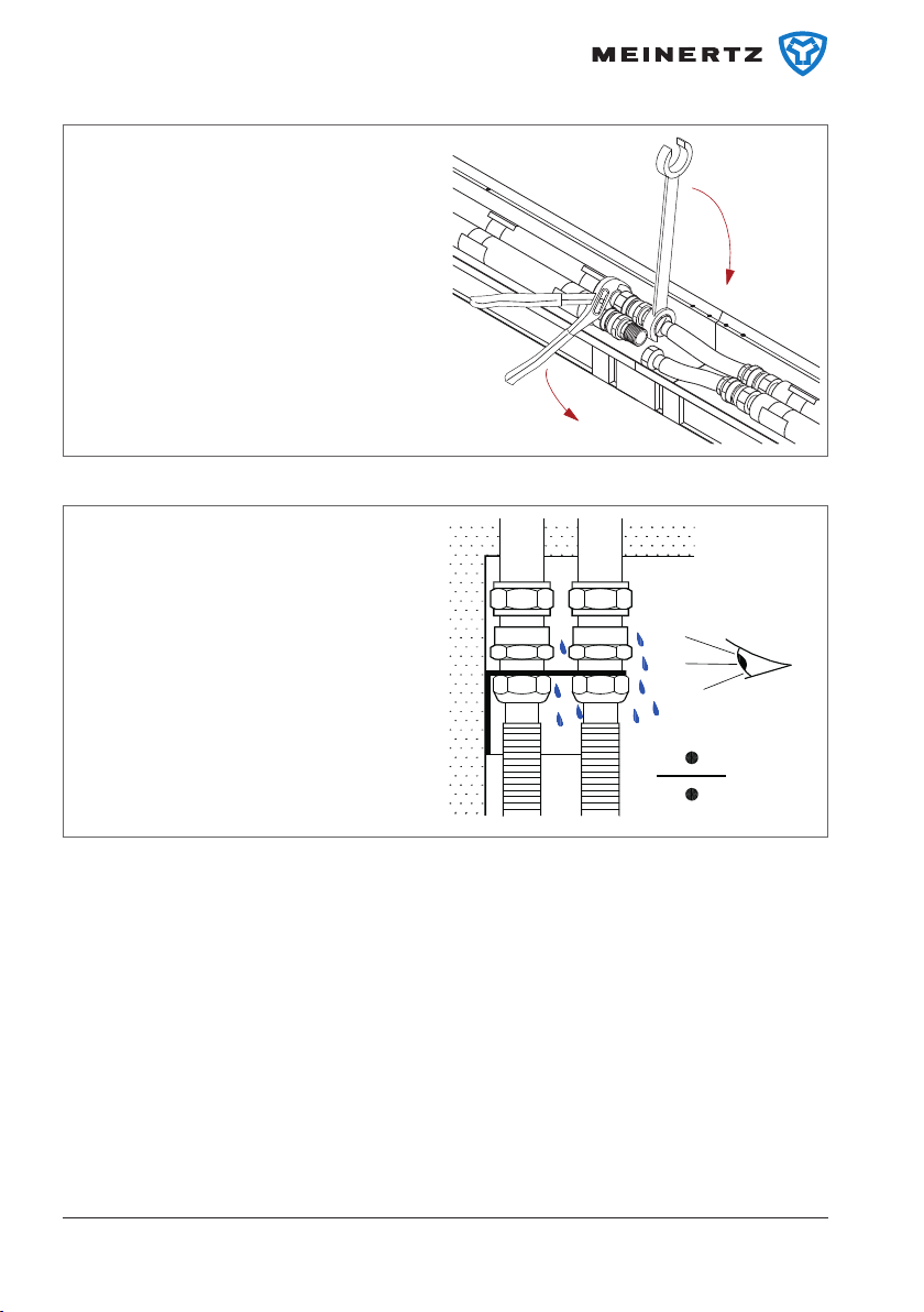
Installing the panel 4/4
Tighten the joints with a moderate torque.
You are recommended to use an NV24 open
ring spanner (order no. 088H4821).

8 Maj 2007
Checking the joints 1/1
After tightening, pressurise the system and
check for possible leaks.
Power connection 1/2
Connect cables from the CHR room
thermostat (or BMS system) and from
the 24 V power supply.
Power connection 2/2
Wiring must be carried out according to the
electrical curcuit diagrams on page 13-14.

Maj 2007 9
Adjusting the panel 1/2
Adapt the panel to the oor height using
the integrated adjusting screws located at
suitable intervals along the full length of the
panel.
Use a 2.5 mm Allen key.
NB! On account of the panel’s load strength,
it is important for all adjusting screws to be
adjusted correctly.
Adjusting the panel 2/2
Put the oor grating in place and check that
it is aligned with the oor surface.
Opening the guide prole 1/4
Remove the oor grating from the panel.

10 Maj 2007
Opening the guide prole 2/4
Release the guide prole from the pipe
xture by pulling sightly.
Repeat this along the full length of the
panel.
Opening the guide prole 3/4
The guide prole can now be lifted to give
access to the base of the panel.
Opening the guide prole 4/4
When the guide prole is closed, secure it
with light pressure on the Velcro pads.

Maj 2007 11
Connecting several panels
in series 1/5
A
Push the panels together.
The joint blocks (A) ensure precise panel
jointing.
Extend the exible pipes to reach the ttings
on the next panel.
Connecting several panels
in series 2/5
To give room for thermal expansion, pull the
panels 2 mm apart.
Connecting several panels
in series 3/5
1
1
2
2
Insert gaskets between the exible pipes
and the ttings before fastening.
12 Maj 2007
Connecting several panels
in series 4/5
Tighten the exible pipes with an NV24 ring
spanner.
NB! Always hold the pipe in place in the
panel with multigrip pliers.
Connecting several panels
in series 5/5
After tightening, pressurise the system and
check for leaks.

24 Vdc
0 Vdc
24 Vdc
0 Vdc
Heat/Cool
RPM (0-10 V)
H. valve +
H. valve -
CHR
24 Vdc
max. 1.1A
Power supply
(22-28 Vdc)
Panels in series
Stand-alone (ST) panel
1
2
3
4
5
6
7
8
9
10
1 2 3 4 5 6
24 Vdc
GND
24 Vdc
GND
H/C
RPM
HV +
HV -
CV +
CV -
Maj 2007 13
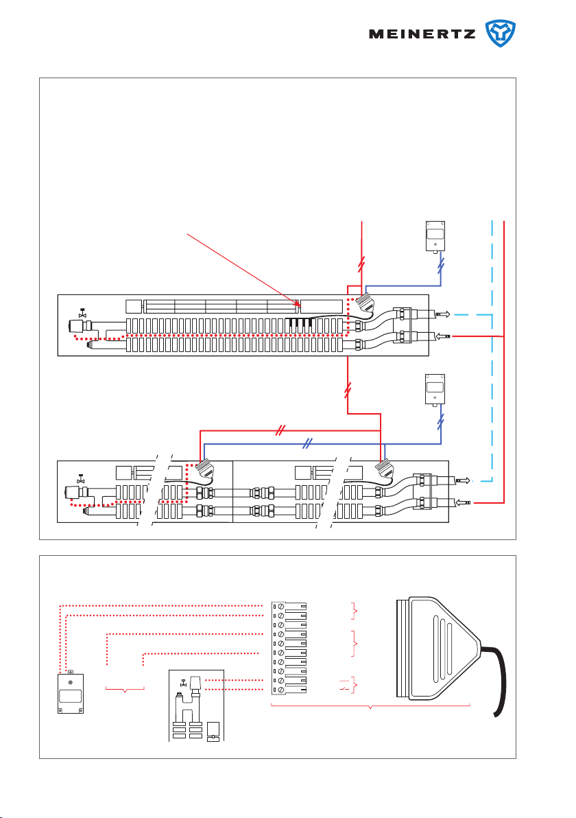
System with CHR room thermostat
A CHR can control up to 10 Convec pan-
els in the same room.
A Convec panel can be supplied with a
valve to control ow through the panel.
Wiring
Supplied from factory
TDM
power
supply
CHR room
thermostat
CHM motor control CHR
room
thermostat
TDM
power
supply
TDM
power
supply
CHR
room
thermostat
NB! CHR room thermostats and CHM motor
control have a common “0”.
1
2
3
4
5
6
7
8
9
10
24 Vdc
GND
24 Vdc
GND
H/C
RPM
HV +
HV -
CV +
CV -
0-10 V0
14 Maj 2007
System with BMS control
A Convec panel can be controlled directly
from a BMS system by a 0-10 V signal.
Control of min. and max. fan speed is
performed by the BMS system. However,
the CHM motor control will continue to
Wiring
Supplied from factory
TDM
power
supply
BMS system
CHM motor control
BMS system
TDM
power
supply
TDM
power
supply
perform the panel control, e.g. stopping
the motor if blocked or the control of
any decentralized valves.
NB! Water supply valves are connected
to cooling outputs 9 and 10.
24 Vdc
0 Vdc
24 Vdc
0 Vdc
Heat/Cool
RPM (0-10 V)
C. valve +
C. valve -
BMS system
24 Vdc
max. 1.1A
Power supply
(22-28 Vdc)
Panels in series
Stand-alone (ST) panel

Maj 2007 15
Operating conditions
Operating pressure . . . . . . . . . . . . . . . . . . . . . . . . . . . . . . . . . . . . . . 10 bar
Test pressure . . . . . . . . . . . . . . . . . . . . . . . . . . . . . . . . . . . . . . . . . . 13 bar
Storage temperature . . . . . . . . . . . . . . . . . . . . . . . . . . . . . . . . . . -10 - 60 °C
Water temperature . . . . . . . . . . . . . . . . . . . . . . . . . . . . . . . . . . . . 8 - 85 °C
Water quality . . . . . . . . . . . . . . . . . . . . . . . . . . . . . . . . . . . . . . . . .VDI 2035

16 Maj 2007
For further information please
contact:
MEINERTZ A/S
Sverigesvej 11
DK-8660 Skanderborg
Phone +45 8652 1811
Fax +45 8652 1515
www.meinertz.com
Table of contents


