Meister Scale P-51D MUSTANG Instruction manual
90” WING SPAN
P-51D MUSTANG
(COPYRIGHT PROTECTED 2014)
ALL RIGHTS RESERVED

GENERAL INSTRUCTIONS
This design is basically an enlargement of the very popular fun scale “Mustang” 60 Size.
You can build it light by using balsa instead of the called for 1/8” mahogany “Door Skin”
which is 36” x 88” per sheet (only one required). We found that the easiest method of
cutting the parts from the D.S. (Door Skin) was to use a “Stanley” utility knife. The
mahogany cuts very easily compared to a jig saw, especially the large fuselage sides.
An 11 lb. Model can be built using balsa instead of mahogany, a small engine and only 4-
channel operation. The prototype has all the goodies, a S.T. 2500 with the described
muffler system and weighs over 14 lbs. It flies very docile at this weight, so do as you
want.
FUSELAGE
1. Cut the fuselage pattern “A” and “B” from the plans and tape together using a
straight edge along the top line to insure alignment of the two patterns. (When
you pick up your door skin from your lumbar yard, have it cut to 65” long and
then to 12” widths. Easier to get home and cut out the parts.)
2. Cut out your sides with the utility knife. Use a razor saw for the notches.
3. You can cut the radius in the lightening holes with many 1/8” holes if you don’t
have a 1” diameter bit.
4. Face the sides to each other per illustration and install all 1/4” x 3/8” balsa
stiffeners to the top and bottom of the sides. See side view for added details.
5. Install the 1/2” x 1-1/16” x 6-5/16” part to the sides as shown being sure it is 1/8”
from the end and flush to the top edge (this piece supports and sets the angle of
the motor mount).
6. Install the 1/2” x 4” x 20-7/8” wing saddle doubler to the sides. Note the 1/8” gap
at the rear.
7. Join the 1/8” balsa nose sheet using 1/32” ply strip to reinforce the joint.
8. Tack glue all bulkheads in place.
9. Make two 90°squares to hold F-3 and F-4 square to the sides.
10. Install the other side gluing only at F-3 and F-4. (Use a large square to check all
around the sides for equal alignment to each other.)

11. If you do not have a fuselage “jig” try this. Draw a 48” line on your bench. Set
F-3 – F-4 over this line (centered). Block the fuselage at F-3 and F-4 so it won’t
move. Pin the ends together. Use the 90°square to align the ends over the line,
being sure that the ends are also straight up and down. Glue.
12. Join the front end at F-2 the same.
13. Install F-1 to the 1/4” ply motor part at 90°. Use a support to insure the angle.
14. Install this assembly to the bottom of the 1/2” x 1-1/16” x 6-5/16” piece. (Be sure
the extra piece of 1/4” x 3/4” x ply is installed under the motor mount. See side
view.)
15. Install a 1/2” x 1/2” x 6-5/16” piece of balsa under the motor mount against the
sides. (Not shown.)
16. Install fuel tank floor and cockpit floor. (The balance of assembly is pretty
obvious. Only helpful hints will be listed hereafter.)
A. The nose cowl should be assembled in place except for the 3/32” planking
which is installed in two stages. Between F-2A and F-3A and then
between F-1A and F-2A. Wet the balsa when bending around the
bulkheads. (Pick super soft balsa for this step.) Cowl is held in place with
screws thru hard wood blocks located at F-1 and F-3.
B. The fuselage ends including the tail post should be 1/2” wide, which
equals the thickness of the rudder.
C. After you have glued the 1/8” balsa front end of the sides to F-1, notice
that the balsa edge is not straight. Sand this straight. Add a piece of 1/4”
balsa to the inside of this balsa side area to provide additional gluing area
for the nose blocks.
TAIL FEATHERS
1. Decide now what size engine you intend to use. If it is larger than 1.8 cu. in. you
best plan on reinforcing. Consider sheeting the surfaces and bracing them or
adding triangles under and over the horizontal stabilizer to provide more gluing
surface.
2. This part is elementary so we leave you to this simple task. Use large DuBro
cotter pin type hinges. Secure with toothpicks. (Be sure and use stiff hard balsa
for the stab spars. See plans.)

WING
1. The wing plans show a separation feature for ease of transport. You must decide
now if you want to incorporate it. Note: Ribs W-1 thru W-4 should be cut from
straight hard balsa or door skin. The spars should be medium to hard balsa.
2. Fabricate the “spar brace” from pine or 1/2” plywood. The width should be
reduced a very small amount to prevent binding when removing. Your local
lumberyard can help you make this part if need be. Put rib angles marks on the
brace.
3. Make up your leading and trailing edge sheet now. Mark them top, bottom, left
right. The aileron portion of the trailing edge sheet should be cut now. Tape it
back into the sheet so it remains intact for early assembly. (After wing is
finished, removal of the tape lets the aileron fall free.) Install the wing dowel and
W-1A to W-1.
4. Pin the sheets and cap strips to the “right” wing plan. Note: There are extension
lines for all hidden lines under the sheets. Install the bottom spar.
5. Tape the mid-spar to the top of the spar brace per spar brace detail. Place on top
of the bottom spar and secure with weights.
6. Pin ribs W-1 to 5 in place. Align W-1 to the marks on the spar brace. Glue a 1/4”
x 1/2” piece of scrap to the mid-spar and W-1. Set the rest of the ribs 90°to the
workbench and secure as shown with 1/4” x 1/2” scrap. Note: If you want a one-
piece wing, glue the spar brace in place.
7. At this point decide if you want to follow the suggested aileron hookup and
sliding servo or a system of your choice.
8. Be sure all shear webbing runs vertical.
9. Because the wing is flat on the bottom it is easy to check for warps. Lay two
straight pieces of balsa on the flat area at the root and tip. Eyeball from the end of
the wing. Do this before installing the top sheeting.
10. If you are installing retracts, give thought to the final weight when choosing
which retract to buy. We recommend Robart #630 Retracts. There are many
choices of wheels. Tally Ho! The Robart military 4” wheels were our choice for
the prototype. To avoid flat spots from sitting on hot asphalt you can install in the
tire round foam strips found in the building industry. They are used as weather
stripping between precast walls.

11. After the wing is finished and bolted to the fuselage, consider making a 1/32” x 1”
x 4-1/2” plywood strap to fit under the wing bolts to keep the rear of the wings
together. You will have to put a notch in W-1 T.E. area for the “wing guide.”
12. The scoop removes separate from the wing. We leave to you the method of
attachment.
GENERAL ADVICE
1. Bolt the engine to the 3/8” x 3/4” x 3”maple blocks using aircraft locking nuts.
These blocks are secured to the motor mount with #8 x 1-1/4” sheet metal screws.
They never come loose!
2. The prototype with retracts and a 54 oz. power plant balanced right on the C.G.
without the receiver, battery pack or 4 servos in the fuselage. If you choose a 40
oz. power plant such as a SAITO 150-180 4-cycle you face either adding lead to
the nose (even if you move all radio gear forward) or using balsa instead of D.S.
and passing up the retract tail wheel. All in all the SAITO engines are hard to
beat from a H.P. vs. cost aspect. Should you opt for the suggested exhaust
system, avoidance of a large exposed muffler is achieved.
3. Adaptor nuts for the spinner are made by Tru-Turn.
4. Gasoline engines, such as a Zenoah G38, can be used by installing a 1/4” ply
firewall. Try to avoid those weighing in excess of 4 lbs.
5. Remember the C.G. location at the main spar. Please balance before flying.
6. If you run into a problem or find an error on the plans, please e-mail

FLYING
1. If you previously built and flew the .40 or .60 size fun scale Mustang, you need
no advice.
2. Set elevator control throws to 1/2” up and 1/2” down. Rudder 1” each way.
Ailerons 1/2” up and 1/2” down. After initial flights set to your taste.
3. Take offs are easy IF you add power slowly and use a little rudder. There is no
need for full throttle take offs.
4. Flying is easy with no bad habits.
5. The “Mustang” will land very slow so don’t try to land too early.
6. If you fly off grass, please move the gear axles forward or you might have a nose
over conditions.
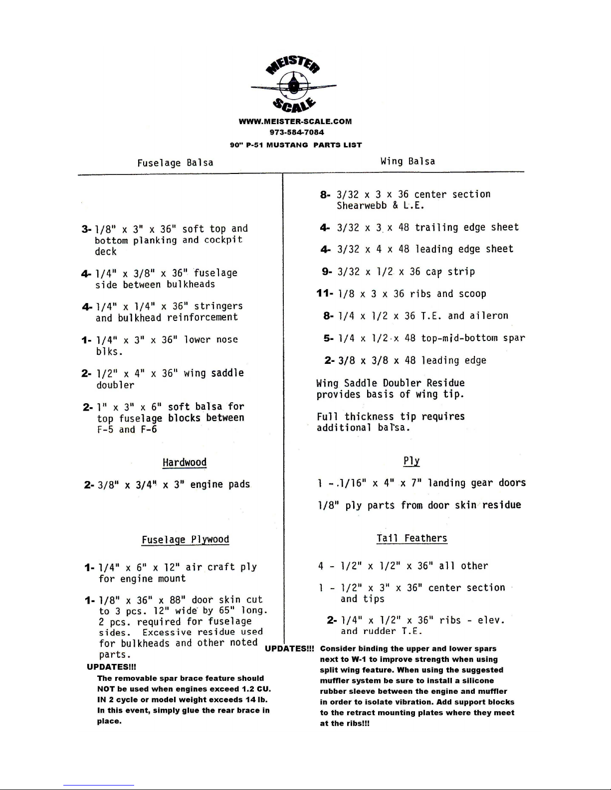
Table of contents
Other Meister Scale Toy manuals


Popular Toy manuals by other brands

Reely Sky
Reely Sky Micro operating instructions

Power Wheels
Power Wheels CADILLAC ESCALADE CUSTOM EDITION N8417 owner's manual

Power Wheels
Power Wheels Jeep Wrangler Owner's manual with assembly instructions

Lionel
Lionel 4-8-4 Niagara owner's manual

Black Horse Model
Black Horse Model ROCKWELL AERO COMMANDER SHRIKE instruction manual

LEGO
LEGO Duplo 10593 Building instructions

Fisher-Price
Fisher-Price Barbie SMART T5407 Owner's manual & assembly instructions

JTA Innovations
JTA Innovations 33" Edge JD manual

Phoenix Model
Phoenix Model SBACH 342 instruction manual

Mattel
Mattel Disney PIXAR Cars HDN02 instructions

Smoby
Smoby Neo House manual

Winfun
Winfun Learn With Me Puppy Pal manual


