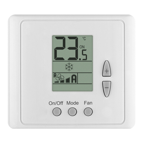
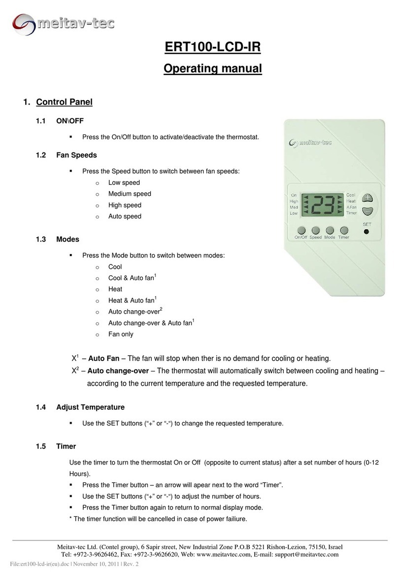
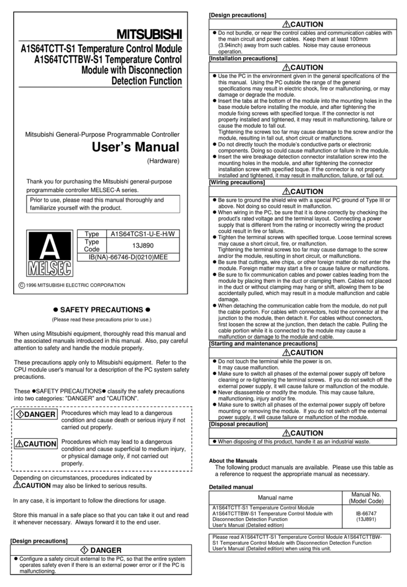
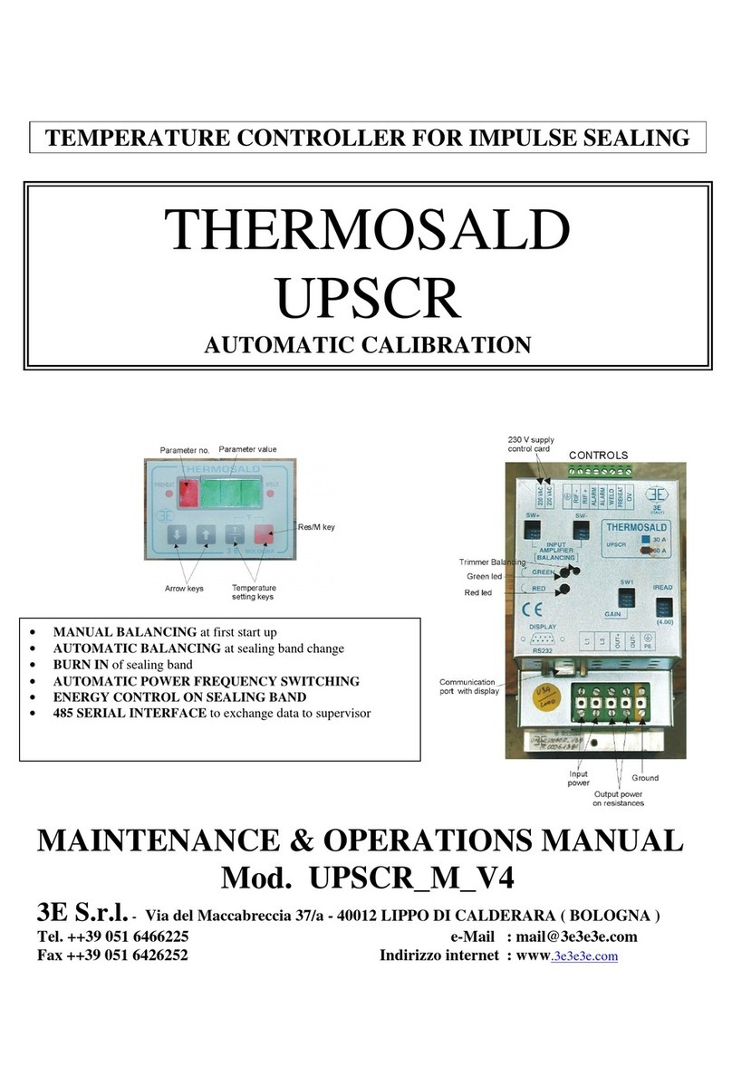
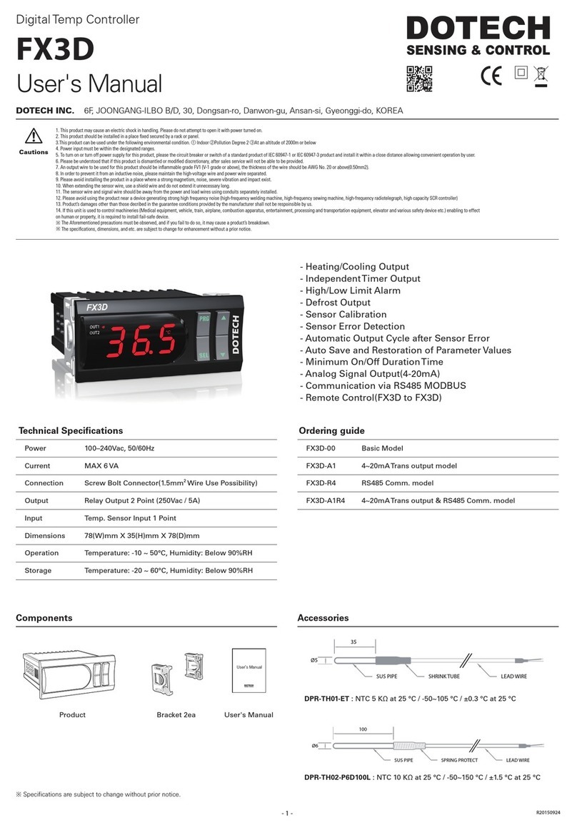
meitav-tec MTS/V50 User manual

Touch Screen Wall Panel
MTS/V500
Owner’s manual and technician settings

-2-
Index
1. Owner’s Manual ………………………………………………..... 3
1.1 Turning the unit ON or OFF………………………………….. 4
1.2 Adjusting the set-point temperature ……………………….. 4
1.3 Switching between System modes………………………….. 5
1.4 Switching between Fan speeds …………………………….. 5
1.5 Fan on demand (Auto fan)….……………………………….. 6
1.6 Faults …...…………….……………………………………….. 6
2. Installation Instructions……..………………………………..... 7
3. Wiring Diagram…………...…..………………………………..... 10
4. DIP Switch settings ……...…..………………………………..... 10
Switch 1 – Temperature readings from CTU or from panel ….. 10
5. Technician Settings …….……………………………………..... 11
P1 – Temperature readings offset …..………………………….. 12
P2 – Enable/Disable screen dimming…………...…………….... 12
P3 – Screen dimming time delay ……………………………….. 13
P4 – Dimming percentage value ……………………………….. 13
P5 – Display brightness………....……………………………….. 14
P6 – Show/Hide lighting button (CTU model dependent) ……. 14
P7 – Enable/Disable the beeper …………………………..……. 15
Exit technician settings and return to normal display……...….. 15

1. Owner’s Manual
-3-
Fan
only
*Auto
mode
Heat Cool *Auto
speed
High Low
Press to switch
between fan speeds:
Med.
*In Auto mode, the active
mode will flash
System ON
Press and hold
to switch between
temperature scales
(set-point must not
be equal to
10ºC/50ºF)
Press and hold
to enter technician
settings
(set-point must be
equal to 10ºC/50ºF)
Set-point adjustment
Temperature scale
Modes
indication
Ambient / Set-point
temperature display
Fan speeds
indication
Press to turn system
ON or OFF
Press to switch
between system
modes:
*In Auto speed, the active
speed will appear
System OFF

1.1 Turning the unit ON or OFF
Press the button to turn the unit ON – system mode and fan
speed symbols will appear on display.
Press again to turn the unit OFF – the symbols will disappear.
1.2 Adjusting the set-point temperature
While the thermostat is ON, press the or buttons – the
set-point temperature will flash.
Press again to adjust the set point.
Unit ONUnit OFF
-4-

Press the button to
switch between system
modes:
1.3 Switching between system modes
Fan
only
Auto
mode
HeatCool
Notes:
- During demand for cooling (cooling active), the will flash.
- During demand for heating (heating active), the will flash.
1.4 Switching between fan speeds
Press the button to
switch between fan speeds:
Low
speed
Medium
speed
High
speed
Auto
speed
Note: When Auto speed Is
selected, the word “AUTO”
and the active fan speed
will appear on display
-5-
The selection of system modes may be disabled depending on type
of the CTU main board connected to the panel.
The selection of fan speeds may be disabled depending on the type
of the CTU main board connected to the panel.

-6-
1.5 Fan on demand (Auto fan)
Press and hold the button to activate or deactivate
fan on demand (Auto fan) function.
Notes:
- When activated, the fan will run with demand for cooling
or heating. The letter “AF” will appear next to the fan
speed symbols.
- The fan on demand function cannot be activated with
“Fan only” mode.
This option may be disabled, depending on the type of the CTU
main board connected to the panel.
1.6 Faults
F8 – Communication fault with the CTU main board
Check wiring connection between the CTU and the room panel
and verify the DIP Switches configuration.
Note: Depending on CTU type, some other symbols may appear on
the display,
AUTO FAN
ʮʥʴʲʬ

2. Installation Instructions
-7-
The MTS/X500 Room panel is designed for flush mounting in the room
to be controlled. It should be located where the occupant can easily
read the display and use the controls.
If the built in temperature sensor is being used to measure room
temperature, the panel should be placed where the temperature is
representative of the general room conditions, away from cold or warm
air draughts, radiant heat and direct sunlight.
The panel should not be installed on an outside wall.
- The standard installation height is 1.5 meter (5 feet) from the floor.
WARNING: Risk of Electric Shock and Property Damage.
Disconnect power supply before making electrical connections.
The installation is to be performed by a qualified electrician.
WARNING: The integrated circuits in the controller are
sensitive to static currents. Take suitable precautions.

2. Installation Instructions (cont’)
-8-
Installation procedure:
1. separate the front display from the back plastic cover by inserting a a
small flat screwdriver into each of the three slots as shown in the
picture and rotating it gently.
2. Remove the front display and keep it in a safe place.
3. Connect the wires as shown in the enclosed wiring diagram. All
terminals accept 1x0.5mm2/24 AWG.
4. If necessary, make changes to the DIP switches position as
explained in this manual.
5. Place the thermostat in the electrical box and tighten up the 2 screws
(Gewiss Box - GW 24 203 or similar).
6. Adapt the front frame-panel into its place, by pushing it towards the
wall.

-9-
2. Installation Instructions (cont’)
1 2
5
3 4
6

-10-
1
2
3
7
8
Room panel
MTS/V500
CTU
Main board
1
2
3
7
8
Switch 1 – Temperature readings from CTU or fom room panel
Switch OFF
Readings from
room panel
(default)
Switch ON
Readings from
CTU
654321
ON
654321
ON
SW2 - Configuration
654321
ON
*Default
3. Wiring diagram
4. DIP Switch settings
Switch 2 – Always OFF
Switch 3 – Always OFF
Switch 4 – Always OFF
Switch 5 – Always ON
Switch 6 – Always ON

5. Technician Settings
Enter technician settings
-11-
(Press and hold)
Adjust the set-point temperature to 10ºC – the button will
appear on display.
To enter technician settings, press and hold the button for
5 seconds.
Use the button to advance to the next parameter.
Use the button to return to return to the previous parameter.
Press the button or wait 60 seconds to exit technician settings
and return to normal display.

5. Technician settings (cont’)
-12-
(Advance)(Return)
Go to last
parameter
P1 Temperature readings
calibration offset
Use the and buttons to
adjust the offset
Range: -6ºC…+6ºC, default 0ºC
(Advance)(Return)
(Advance)
P2 Enable/Disable screen
dimming
Using the and buttons,
select between:
00 – Disable screen dimming
01 – Enable dimming (default)
If no key is pressed, during
the time set in parameter P3,
the display will dim

- 13 -
P3 Screen dimming time delay
Using the and buttons,
adjust the time delay before the
screen will dim
Range: 0...99 sec., default: 5 sec.
5. Technician settings (cont’)
(Advance)(Return)
(Advance)(Return)
(Advance)(Return)
P4 Dimming percentage value
Using the and buttons,
adjust the dimming percentage
value
Range: 10...90%, default: 10%

-14-
P5 Display brightness
Using the and buttons,
adjust the time display brightness
Range: 50...100%, default: 100%
(Advance)(Return)
P6 Show/Hide lighting button
Using the and buttons, select
between:
0 – Hide the lighting button
1 – Show the lighting button (default)
Note: the lighting button will only be
available with some CTU types.
It will never appear on display
when the CTU does not support
the lighting feature
5. Technician settings (cont’)
(Advance)(Return)
(Advance)(Return)

-15-
Important! Reset the set-point temperature to the desired value
Press the button to
return to parameter P1.
Press the button or
wait 60 seconds to exit
technician settings mode
and return to normal display.
(Advance)(Return)
5. Technician settings (cont’)
P7 Enable/Disable the beeper
Using the and buttons,
select between:
0 – Disable the beeper
1 – Make the panel beep
whenever a button is pressed

www.meitavtec.com
This manual suits for next models
1
Table of contents
Other meitav-tec Temperature Controllers manuals