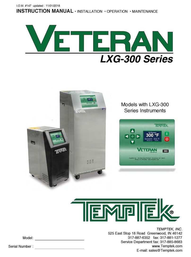
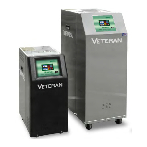
Temptek VETERAN LS Series User manual

I.O.M. #092 12/06 updated 02/2013
INSTRUCTION MANUAL • INSTALLATION • OPERATION • MAINTENANCE
TEMPTEK, INC.
525 East Stop 18 Road Greenwood, IN 46142
317-887-6352 fax: 317-881-1277
Service Department fax: 317-885-8683
www.TempTek.com
e-mail: [email protected]
Models with ‘LS’ Series Instrument.


INSTRUCTION MANUAL
VETERAN TEMPERATURE CONTROL UNIT
with ‘LS’ SERIES INSTRUMENT
COVERING
INSTALLATION
OPERATION
MAINTENANCE
TEMPTEK, INC. 525 East Stop 18 Road Greenwood, IN 46142
317-887-6352 fax: 317-881-1277 Service Department fax: 317-885-8683

Temperature Control Units : With ‘LS’ Series Instrument
Page: 4
TEMPTEK, INC.
525 East Stop 18 Road Greenwood, Indiana 46142
317-887-6352 Fax: 317-881-1277
Service Department Fax: 317-885-8683
www.Temptek.com
TABLE OF CONTENTS
QUICK START-UP GUIDE 6
QUICK TROUBLESHOOTING GUIDE 7
1.0 GENERAL 9
1.1 Safety 10
1.2 Efficiency 10
1.3 Typical Label Placement 10
1.4 Component placement 11
2.0 INSTALLATION 13
2.1 General 14
2.2 To and from process connections 14
2.3 Water supply connection 15
2.4 Drain connection 15
2.5 Electrical connection 16
3.0 START UP SEQUENCE 19
3.1 General 20
3.2 System fill/operations procedure 20
3.3 Instrument operation 25
3.4 Shut down/disconnect sequence 30
4.0 TROUBLESHOOTING 33
4.1 Unit will not start (Power light off) 34
4.2 Unit will not start (Power light on) 34
4.3 Unit stops 34
4.4 Unit overheats 35
4.5 Unit underheats 36
4.6 Pressure relief valve leaks 37
4.7 Cooling valve fault 38
5.0 MAINTENANCE 35
5.1 Pump seal replacement 36
5.2 Heater replacement 39
5.3 PVTTM cooling valve service 41
5.4 Probe calibration 43
5.5 Voltage changeover 45
5.6 Sensor probe service 48
5.7 Pressure switch service 50
5.8 Instrument service 51
5.9 Celsius temperature display 53
5.10 Electronic instrument repair policy 54
And procedure

Temperature Control Units : With ‘LS’ Series Instrument
Page: 5
TEMPTEK, INC.
525 East Stop 18 Road Greenwood, Indiana 46142
317-887-6352 Fax: 317-881-1277
Service Department Fax: 317-885-8683
www.Temptek.com
6.0 COMPONENTS55
6.1 Mechanical system 56
6.2 Electrical system 58
7.0 RELATED DRAWINGS 61
7.1 Physical 62
7.2 Electrical 63
7.3 Circuit schematic 64
7.4 Regulator/bypass installation 65
7.5 Dual zone dolly 66
7.6 Stacking rack 67
8.0 APPENDIX 69
8.1 Specifications 70
8.2 Model # and suffix coding 71
8.3 Interpretation of process pressure gauges 72
8.4 Mold purge operation 73
8.5 Closed Circuit Operation 74
8.6 AS5 pump parts list - 1/2 HP to 1 HP 75
8.7 AS5 pump parts list - 1 1/2 HP to 3 HP 76
8.8 Parts list - LS instrument 77

Temperature Control Units : With ‘LS’ Series Instrument
Page: 6
TEMPTEK, INC.
525 East Stop 18 Road Greenwood, Indiana 46142
317-887-6352 Fax: 317-881-1277
Service Department Fax: 317-885-8683
www.Temptek.com
YES
YES
YES
YES
YES
YES
YES
YES
YES
YES
YES
YES
YES
YES
YES
YES
YES
YES
...
...
YES
YES
NO
NO
INSTALLED TO CORRECT
ELECTRICAL SUPPLY?
ELECTRICAL SUPPLY
LISTED ON DATA TAG
BE CERTAIN UNIT IS INSTALLED
TO PROPER ELECTRICAL SUPPLY
...
...
NO
NO
UNIT INSTALLED TO
PROCESS CORRECTLY?
'TO PROCESS' TO 'WATER IN' ON
PROCESS MANIFOLD
'FROM PROCESS' TO 'WATER OUT'
ON PROCESS MANIFOLD
NO
NO
WATER SUPPLY OPEN AND
PRESSURE ADEQUATE?
WATER SUPPLY PRESSURE MUST BE
OVER 15 PSI FOR UNIT TO START
NO
NO
DRAIN LINE CORRECTLY
INSTALLED?
CONNECT DRAIN LINE TO PROPER
RETURN SYSTEM
NO
NO
ENGAGE POWER SUPPLY...
'POWER' LIGHT ON?
CHECK DISCONNECT FUSE OR
TRANSFORMER FUSE
TURN UNIT 'ON' AND
SELECT SETPOINT
QUICK START-UP GUIDE

Temperature Control Units : With ‘LS’ Series Instrument
Page: 7
TEMPTEK, INC.
525 East Stop 18 Road Greenwood, Indiana 46142
317-887-6352 Fax: 317-881-1277
Service Department Fax: 317-885-8683
www.Temptek.com
NO
NO
NO
NO
NO
NO
NO
NO
NO
NO
YES
YES
YES
YES
YES
YES
YES
YES
YES
YES
UNIT WILL NOT START
"POWER" LIGHT ON?
WATER SUPPLY
PRESSURE LOW? ENGAGE POWER
MAIN POWER SUPPLY
"ON"?
REPLACE TRANSFORMER
FUSE
PRESSURE SWITCH OPEN
SUPPLY UNIT WITH 15 PSI
MOTOR OVERLOAD
RELAY OPEN?
RESET OVERLOADS
ADJUST PROCESS FLOW
HIGH TEMP LIMIT
SWITCH OPEN?
INSTRUMENT DEFECTIVE
REPLACE
TEMPERATURE OVER 256∞
ALLOW UNIT TO COOL
NO
NO
OR
OR
NO
NO
OR
OR
REPLACE MOTOR/GEARBOX
ASSEMBLY
OR
OR
OR
OR
BLOCKED WATER CHANNEL
IN TOOLING OR MOLD
NO
NO
NO
NO
NO
NO
NO
NO
NO
NO
YES
YES
YES
YES
YES
YES
YES
YES
YES
YES
UNIT STOPS
"POWER" LIGHT ON?
WATER SUPPLY
PRESSURE LOW? ENGAGE POWER
MAIN POWER SUPPLY
"ON"?
REPLACE TRANSFORMER
FUSE
PRESSURE SWITCH OPEN
SUPPLY UNIT WITH 20 PSI
MOTOR OVERLOAD
RELAY OPEN?
RESET OVERLOADS
ADJUST PROCESS FLOW
HIGH TEMP LIMIT
SWITCH OPEN?
INSTRUMENT DEFECTIVE
REPLACE
TEMPERATURE OVER 256∞
ALLOW UNIT TO COOL
NO
NO
NO
NO
YES
YES
YES
YES
YES
YES
UNIT OVERHEATS
INADEQUATE WATER
SUPPLY PRESSRE?
WATER SUPPLY PRESSURE MUST BE
SUFFICIENT FOR OPERATING TEMPERATURE
AVT COOLING VALVE
DEFECTIVE?
CHECK VALVE WIRE
HARNESS
CLEAN/REPLACE
BALL VALVE ASSEMBLY
OR
OR
REDUCE HIGH DRAIN
LINE PRESSURE
OPEN23 CLOSED
DRAIN LINE VALVE
NO
NO
YES
YES
KINKED HOSE OR
EXCESSIVE PIPE FITTINGS
LOW PROCESS
FLOW RATE?
CHECK FOR A CLOSED
PROCESS VALVE
YES
YES
OR
OR
REPLACE PROBE
CONTROL PROBE
DEFECTIVE?
CHECK FOR WATER IN
PROBE CONNECTION
INSTRUMENT DEFECTIVE
REPLACE
OR
OR
NO
NO
NO
NO
NO
NO
YES
YES
YES
YES
UNIT UNDERHEATS
PROCESS WATER
LEAKAGE?
HEATER ELEMENT
DEFECTIVE?
REPLACE HEATER
OR
OR
DETERMINE IF UNIT
CAPACITY TOO LOW
OR
OR
YES
YES
CHECK FOR A DEFECTIVE
AVT COOLING VALVE
LEAKING WATER PRESSURE
RELIEF VALVE
CHECK FOR EXCESSIVE
UNIT RADIATION
NO
NO
YES
YES
REPLACE PROBE
CONTROL PROBE
DEFECTIVE?
CHECK FOR WATER IN
PROBE CONNECTION
INSTRUMENT DEFECTIVE
REPLACE
HEAT LOSS?
QUICK TROUBLESHOOTING GUIDE
DRAIN LINE
OBSTRUCTED?

Page: 8
THIS PAGE INTENTIONALLY BLANK

Temperature Control Units : With ‘LS’ Series Instrument
Page: 9
TEMPTEK, INC.
525 East Stop 18 Road Greenwood, Indiana 46142
317-887-6352 Fax: 317-881-1277
Service Department Fax: 317-885-8683
www.Temptek.com
1.0 GENERAL
1.1 SAFETY
1.2 EFFICIENCY
1.3 TYPICAL LABEL PLACEMENT
1.4 COMPONENT PLACEMENT

Temperature Control Units : With ‘LS’ Series Instrument
Page: 10
TEMPTEK, INC.
525 East Stop 18 Road Greenwood, Indiana 46142
317-887-6352 Fax: 317-881-1277
Service Department Fax: 317-885-8683
www.Temptek.com
1.1 SAFETY
A. It is important to become thoroughly familiar with this manual and
the operating characteristics of the equipment.
B. Several important references are made to safety considerations
in this manual. It is the owner’s responsibility to assure proper
operator training, installation, operation, and maintenance of the
water temperature controller with instrument.
1.2 EFFICIENCY
A. Long term efficiency of operation is largely determined by proper
maintenance of the mechanical parts of the unit and water quality.
We recommend filtering where required to prevent solids from
plugging critical parts such as pumps, heaters and seals. The
services of a competent water treatment specialist must be
obtained and his recommendations followed. Temptek accepts no
responsibility for inefficient operation, damage caused by foreign
materials, or failure to use adequate water treatment.
1.3 TYPICAL LABEL PLACEMENT
Warning Label
Summarizes the safety precautions
when unit is in use.
Process Connection Label
Details process connections hook-up.
Unit Data Tag
Details unit Serial Number, voltage and
other important unit information.

Temperature Control Units : With ‘LS’ Series Instrument
Page: 11
TEMPTEK, INC.
525 East Stop 18 Road Greenwood, Indiana 46142
317-887-6352 Fax: 317-881-1277
Service Department Fax: 317-885-8683
www.Temptek.com
1.4 COMPONENT PLACEMENT
A. The temperature controller is designed to circulate temperature
stabilized water through the process system to result in process
temperature control.
B. Please note that the ability of the equipment to achieve this
objective is significantly affected by the method of installation.
C. If the operator has any questions, contact the Sales or Service
Department at 317-887-0729.
Pump
Thermoformed
Cover Panel
Vented Stainless
Steel Cabinet
Pump Motor
Caster
Cooling Cylinder
Heating Cylinder
Temperature Sensor
Electrical Panel
(Inside stainless steel cabinet.)
Cooling Valve
Heater
Instrument
Pressure Gauges

Temperature Control Units : With ‘LS’ Series Instrument
Page: 12
TEMPTEK, INC.
525 East Stop 18 Road Greenwood, Indiana 46142
317-887-6352 Fax: 317-881-1277
Service Department Fax: 317-885-8683
www.Temptek.com
Manual & Quick
Start Guide
Lift-Off Cover
Panel
Electrical Panel

Temperature Control Units : With ‘LS’ Series Instrument
Page: 13
TEMPTEK, INC.
525 East Stop 18 Road Greenwood, Indiana 46142
317-887-6352 Fax: 317-881-1277
Service Department Fax: 317-885-8683
www.Temptek.com
2.0 INSTALLATION
2.1 GENERAL
2.2 TO AND FROM PROCESS CONNECTIONS
2.3 WATER SUPPLY CONNECTION
2.4 DRAIN CONNECTION
2.5 ELECTRICAL CONNECTION

2.1 GENERAL
A. All process piping materials such as hose, rigid piping, valves or
filters, used in process water piping circuitry must be rated for
350°F minimum temperature and 200 PSI minimum pressure.
B. Be certain all process piping materials have the equivalent or larger
diameter of the particular process connection.
Temperature Control Units : With ‘LS’ Series Instrument
Page: 14
TEMPTEK, INC.
525 East Stop 18 Road Greenwood, Indiana 46142
317-887-6352 Fax: 317-881-1277
Service Department Fax: 317-885-8683
www.Temptek.com
To process connection:
Connect to “water in” on process manifold
From process connection:
Connect to “water out” on process manifold
Drain connection:
Connect to one of the following:
(Depending on water supply source)
• plant’s open drain
• tower water system return
• chilled water system return
Water supply connection:
Connect to one of the following:
• plant’s city water source
• well water source
• tower water supply
• chilled water supply
2.2 TO AND FROM PROCESS CONNECTIONS
A. Connect the unit’s To Process port to the Water In port on the
process manifold.
B. Connect the unit’s From Process port to the Water Out port on the
process manifold.
C. Please note: Process water piping circuitry should be designed to
avoid an excessive use of elbows and/or lengths of pipe or hose.
If hose is the material of choice, avoid tight twists or curls and
excessive lengths.
D. Valves and filters may be installed in the process water piping
circuitry to facilitate service and maintenance, provided that such
devices maintain the full inside diameter of the process connection.
If installed, all such devices must be open and clean during unit
operation.

2.3 WATER SUPPLY CONNECTION
A. Connect the unit’s Water Supply port to the plant’s city water, well
water, tower water or chilled water supply.
B. Water supply pressure requirements vary with operating
temperatures. Figure 2.2A shows the required operating water
supply pressures for various operating process temperatures. The
required water supply pressure retains process water in a liquid
state at temperatures over 180°F. Failure to maintain the required
water supply pressure will cause premature failure of and increase
maintenance in susceptible areas such as the shaft seal and heater.
C. The factory recommended
minimum operating water supply
pressure requirement is identified
on the unit’s data tag (figure 2.2B).
D. Static water supply pressure can
be determined at the unit’s location
by reading the unit’s 0-160 PSI
pressure gauges when the unit’s
pump motor is OFF.
E. If water supply pressure as read
on the unit’s pressure gauges
exceeds 75 PSI, a pressure
reducing valve must be installed
in the water supply line (refer
to section 7.4 of this manual for
installation information). The factory
recommended ‘regulated pressure
out’ is 55 PSI (figure 2.2C ).
2.4 DRAIN CONNECTION:
A. Connect the unit’s DRAIN port to
one of the following, determined by
the water supply source:
1. Open drain for well or city water supply.
2. Tower water system return for tower system water supply.
Temperature Control Units : With ‘LS’ Series Instrument
Page: 15
TEMPTEK, INC.
525 East Stop 18 Road Greenwood, Indiana 46142
317-887-6352 Fax: 317-881-1277
Service Department Fax: 317-885-8683
www.Temptek.com
Typical Data Plate Figure 2.2B
Typical pressure reducing valve
installation (shown on S-925).
Figure 2.2C
180°F
20 PSI
190°F
25 PSI
200°F
30 PSI
210°F
35 PSI
220°F
40 PSI
230°F
45 PSI
240°F
50 PSI
250°F
55 PSI
OPERATING TEMPERATURE
WATER SUPPLY PRESSURE
Figure 2.2A

Temperature Control Units : With ‘LS’ Series Instrument
Page: 16
TEMPTEK, INC.
525 East Stop 18 Road Greenwood, Indiana 46142
317-887-6352 Fax: 317-881-1277
Service Department Fax: 317-885-8683
www.Temptek.com
3. Chilled water system return for chilled water system supply.
B. The factory recommends a minimum of 10 psi pressure differential
between the water supply and drain
line for proper cooling.
C. For most applications, the drain line
should not be valved. However,
for installations with a pressurized
drain system, it may be necessary
to install a valve in the drain
line. In such cases, the installed
valve must be fully opened after
installation and the valve handle
removed to prevent operating the
unit with a closed drain valve. The
valve handle can be reattached to
the valve body when it is necessary
to close the valve (figure 2.3A).
D. CAUTION: The unit must never be operated with a closed drain line
valve. A closed drain line valve prevents adequate system cooling
and will lead to unit overheating. Overheating of the unit may lead
to unit damage and/or serious personal injury.
2.5 ELECTRICAL CONNECTION
A. NEMA 1 MODELS
1. Electrical power supply requirements for Nema 1 units
are identified on the equipment data tag. Verify that
available voltage supply is the same as the unit’s voltage
requirements.
WARNING: DO NOT CONNECT THE UNIT TO A
VOLTAGE SUPPLY SOURCE NOT EQUAL TO THE
UNIT’S VOLTAGE REQUIREMENTS AS SPECIFIED ON
THE UNIT’S DATA PLATE.
Use of incorrect voltage will void the unit’s warranty and
cause a significant hazard that may result in serious
personal injury and/or unit damage.
2. For units with 10 and 16 KW heaters, a four conductor
cable, 10 foot in length, has been provided for connection to
an operator supplied fused disconnect.
3. For units with 24 and 34 KW heaters, the operator must
provide a four conductor power cable and the fused
disconnect.
4. The owner supplied fused disconnect must be sized and
Typical drain valve installation
(Shown on S-925)
Figure 2.3A

Temperature Control Units : With ‘LS’ Series Instrument
Page: 17
TEMPTEK, INC.
525 East Stop 18 Road Greenwood, Indiana 46142
317-887-6352 Fax: 317-881-1277
Service Department Fax: 317-885-8683
www.Temptek.com
installed according to the unit’s power supply requirements
and local electrical codes.
B. NEMA 12 MODELS
1. Nema 12 units are designated by the letter “J” in the model
number suffix. These units are constructed with a dust tight
electrical enclosure and branch circuit fusing. Electrical
power supply requirements are identified on the equipment
data tag. Verify that available voltage supply is the same as
the unit’s voltage requirements.
WARNING: DO NOT CONNECT THE UNIT TO A
VOLTAGE SUPPLY SOURCE NOT EQUAL TO THE
UNIT’S VOLTAGE REQUIREMENTS AS SPECIFIED ON
THE UNIT’S DATA PLATE.
Use of incorrect voltage will void the unit’s warranty and
cause a significant hazard that may result in damage to the
unit or serious personal injury.
2. Appropriate conduit and fittings should be selected which
will maintain the integrity of the cabinet.
3. Supply a power conductor sized according to the unit’s
power supply requirements. Connect the power conductor
to the unit’s power supply
entry terminal block.
C. CONTROL CIRCUIT WIRING
1. The unit’s supplied control
circuit is 110 volt, 1 phase,
60 cycle. The control circuit
is supplied by the factory
installed transformer.
A control circuit fuse is
provided (figure 2.5C).
D. GENERAL
1. Make certain all ground connections to the unit are properly
affixed. A proper connection to earth ground is required. A
conduit ground is not a reliable conductor!
2. Make certain the power conductor, disconnecting means,
and fusing are properly sized according to the unit’s power
supply requirements.
3. Make certain all electrical connections are tightly affixed.
Any loose wiring connections must be tighten before
engaging the power supply.
Control circuit transformer fuse Figure 2.5C

Temperature Control Units : With ‘LS’ Series Instrument
Page: 18
TEMPTEK, INC.
525 East Stop 18 Road Greenwood, Indiana 46142
317-887-6352 Fax: 317-881-1277
Service Department Fax: 317-885-8683
www.Temptek.com
Power Entry
Covered
Low Water
Pressure Switch
Control Transformer Pump Motor
Controller
Terminal Strip Heater
Contactor
Transformer
Fuse Blocks
4. Make certain no moisture or standing water is present
inside the electrical cabinet.

Temperature Control Units : With ‘LS’ Series Instrument
Page: 19
TEMPTEK, INC.
525 East Stop 18 Road Greenwood, Indiana 46142
317-887-6352 Fax: 317-881-1277
Service Department Fax: 317-885-8683
www.Temptek.com
3.0 OPERATIONS
3.1 GENERAL
3.2 MACHINE START UP/OPERATIONS PROCEDURE
3.3 INSTRUMENT OPERATION
3.4 SHUT DOWN/DISCONNECT PROCEDURE

Temperature Control Units : With ‘LS’ Series Instrument
Page: 20
TEMPTEK, INC.
525 East Stop 18 Road Greenwood, Indiana 46142
317-887-6352 Fax: 317-881-1277
Service Department Fax: 317-885-8683
www.Temptek.com
3.1 GENERAL
A. Failure to follow the factory required operation procedures may
adversely affect the unit’s ability to adequately control process
temperature and may create a hazardous operating condition which
may result in unit damage or serious operator injury.
B. The Operations segment of this manual is outlined below:
3.2 Machine start-up/operations procedure - follow this
segment to start the unit after the initial installation or to
restart the unit after reinstallation to the same or different
process. This section includes information on system fill,
electric motor phasing (pump rotation) and process flow
adjustments.
3.3 instrument Operation - follow this segment to start up and
operate the instrument. This section includes information
on automatic and manual venting, setpoint selection and
adjustment, and feature explanations.
3.4 Shut down procedure - follow this segment to shut down
the unit. This segment includes information on system cool
down, shut down, electrical power supply precautions, and
disconnection from the system.
3.2 MACHINE START UP/OPERATIONS PROCEDURE
A. SYSTEM FILL
1. Engage the water supply source by opening the water
supply valve (customer installed) at the unit’s location. If a
valve is not installed, engage the water supply source at the
plant’s water supply central control point.
2. Once the water supply source is open, the unit will
fill automatically. Allow a few moments for the unit to
completely fill. The operator can determine the unit is
properly filled when the To Process pressure gauge and the
From Process pressure gauge stabilize at equal or closely
similar pressure.
3. The operator must check for any water leakage in the
unit’s mechanical system, the process, and throughout the
plant’s water supply system. If a water leak is observed, the
operator must disengage the water supply system, relieve
all pressure, and repair the leak. The operator must verify
the leak is repaired by refilling the system as outlined in this
procedure.
Table of contents
Other Temptek Temperature Controllers manuals
Popular Temperature Controllers manuals by other brands
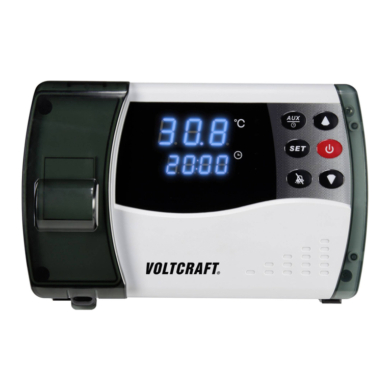
VOLTCRAFT
VOLTCRAFT ECB-1000P operating instructions
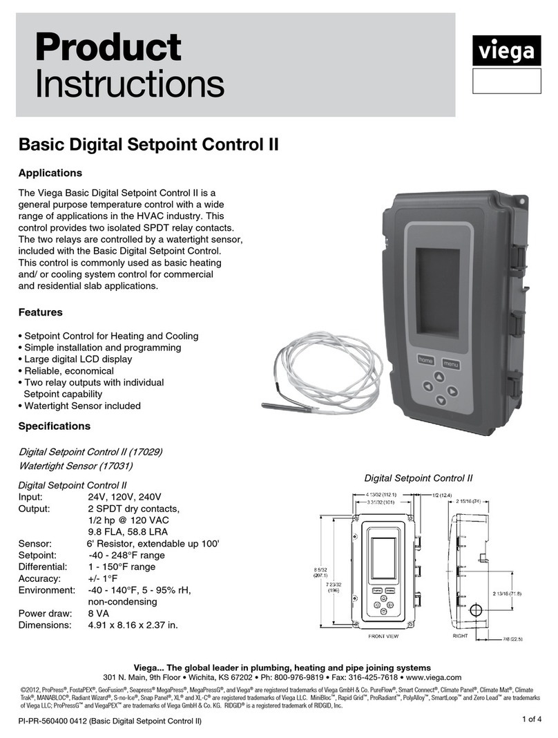
Viega
Viega Basic Digital Setpoint Control II Product instructions

Eurotherm
Eurotherm 2208L Installation and operating instructions
Auber Instruments
Auber Instruments WS Series Operation & instruction manual
Oregon Scientific
Oregon Scientific THGN810 user manual

resideo
resideo ADEMCO TS300 Installation and operating instructions
Omron
Omron E5GN-QTD manual
MULTISPAN
MULTISPAN UTC-2202G Installation guidelines
Ropex
Ropex RESISTRON RES-403 operating instructions
Specac
Specac 523-211 quick start guide

Honeywell
Honeywell FIRE-LITE ALARMS W-H355 Installation and maintenance instructions

Sensored Life
Sensored Life MarCELL Pro quick start guide
