Melco Hi Pro Operation manual

Eii=
MAIGGIORE ELECTRONIC LAB.
Hi Pro
Repeater
Owner's Operating
And Maintenance
Manual
'J
- .. _-

Maggiore Electronic Laboratory
DESCR I PT I 0N
This Repeater is an extremely rugged completely solid state Repeater.
State of the art devices such as ICs, FETs, Varactor and Zener diodes are engi-
neered into tight knit straightforward electronic. design throughout both trans-
mitter and receiver. Reliablity,low current demand, compactness, unexcelled
performance and ease of operation are the net result.
The dual conversion receiver with its FET front end and high-Q circuits boasts
low noise and sensitivity of 0.3 uv or less. Signal gain of 90 db or more is
accomplished from the IF amplifier. The need for additional front end RF am-
plification is thus eliminated. Zener regulated crystal-controlled osciHator
produces unmat:ched stability. Audio reproduction is of an unusually high order
of distortion free clarity. Advanced squelch prevents chopping.
The transmitter section on the Mkl will produce a nominal of 15 watts RF output
(25 watts VHF,18 watts UHF on the Mkll). Again, a Zener regulated crystal oscil-
lator is employed for initial frequency stability. High-Q and shielded stages
provide minimum interstage spurious reaction. A low pass filter is placed at the
output to further insure undesirable frequency products not being emitted. On bat-
tery backup, output power drops to 10 watts to conserve battery power.
All circuitry is constructed in a series of modules which are easily removable
for servicing.
A modern style, small size and low profile design compliment the unit.
SECTION 1 lNSTALLATloN
1.1 Unpacking.
Carefully remove your Repeater from the packing carton and examine it for signs
of shipping damage. Should any shipping damage be apparent, notify the deliver-
ing carrier immediately, stating the full extent of the damage. It is recom-
mended you keep the shipping carton in the event storage, moving, or reshipment
becomes necessary.
1.2 Location.
Where you place the Repeater is not very critical and should be governed by con-
venience and accessibility. Since the unit is so compact, many possibilities
present themselves. BE SURE T0 ALLOW FOR PLENTY 0F VENTILATloN BOTH ABOVE AND
BELOW THE REPEATER. A FAN MOUNTED IN THE REAR WITH AIR FLOW DIRECTED TOWARD
THE POWER AMPLIFIER WOULD BE ADVANTAGEOUS, BUT NOT NECESSARY IF TEMPERATURES
REMAIN BELOW 900 FARENHEIT.
1.3 Power Requirements.
The Standard Repeater is supplied ready to operate from any 110v ac 60 cy source.
A 12 volt battery negative ground system may also b,£ incorporated. Some pre~
cautions must be taken however to the condition
Items such as low battery, poor voltage regulat
tion of your Repeater.
f the electrical system.
n,`etc., will impair opera-

Maggiore Electronic Laboratory
I.3 High noise generation or low power delivery and hum can be traced to these
deficiencies. Low voltage while under load will not produce satisfactory
results from your Repeater receifer, and transmitter output wHl be
greatly impaired.
CAUT I ON :
Excessive Voltage (above 130v ac -15v dc) will cause damage to
your Repeater. Be sure to check the source voltage before con~
necting the power cord. Do not defeat ground pin on power cord.
S use a
rounded outlet.
1.4 Antenna
The most important single item that will influence the performance of any
communication system is the antenna. For that reason, a good high quality
gain antenna of 50 ohms impedance is recorrmended. When adj.usting your antenna,
by all means, foHow the manufacturer`s instructions. There are some pitfaHs
to be aware of . For example, do not attempt to adj.ust an antenna for lowest
VSWR with the Repeater Transmitter. Rather use a low power transmitter and
an in line watt meter sjmi]iar to the Drake WV-4 or Bird Model 43 with
proper cartridge.
The RF coaxial connectors on the rear chassis mates with a standard
PL-259 connector.
~` SECTloN 2 0PERATloN
2.1 Initial Preparations.
a. Connect the microphone to the microphone j.ack.
` b. Connect the antennas or duplexer cables, to the antenna coax connectors.
Make sure the coax lines are of the correct impedance (50 ohms) and is
neither shorted nor open circuited.
c. Make sure the function switch is in the simp]ex position.
d. If deluxe auto patch or basic auto.pat:ch is used, connect phone line
and on deluxe auto patch interconnecting cable.
2.2 Operation.
When the function switch is set to simplex position, the repeat mode is dis-
abled. Keying the local microphone will be the only way to operate the trans-
mitter, other than in auto patch mode.
2.3 Reception.
Adj.ust the volume control on front panel to a com for.table listening level
with squelch control on rear open.
Adj.ust rear volume control only if necessary.
Carefully adj.ust the squelch control on rear panel clockwise,(with no
receiver input) until the noise j.ust disappears. This is the proper squelch
theshold setting and must be done when no signal is present. Your Repeater
will now remain silent until an incoming signal is received which opens
the squelch. If the squelch is unstable due to.ngthe reception of weak or
unstable signal, adj.ust the squelch control r:}jr:her until the desired
threshold is obtained.

Maggiore Electronic Laboratory
2.3 d. The meter indicates the signal strength and proper frequency setting
of the incoming stations and is calibrated in S units and plus or minus
of center f requency.
2.4
2.5
Transmi tt i ng .
Excessive audio compression is adjusted by exciter board audio adj.ustment,
excessive repeater deviation is adj.usted by deviation control on trans-
mitter exciter board.
Transmitter power adjustment.
Final power output may be changed by adj.usting power level control on
exciter board.
SECTloN 3 MAINTENANCE
3.1
3.2`
3.3
The necessity of completely realigning the unit is unlikely. The most
common cause of breakdown is component failure. It is felt that the
average owner would not have the necessary equipment and facilities to
accomplish realignment in any case, if it did become necessary. If one
did have such facilities and instruments, it is highly likely he would
be a FM technician and instructions for alignment would be unneccsary.
All of the foregoing is to say that this Repeater is a complicated and
e]e`ctronicaHy speaking, delicate machine. Great care and precision
are employed in its manufacture and warranty service is provided to
insure that it meets specifications. Adj.ustments not outlined herein
should not be undertaken unless the owner is skilled as a technician.
Transmi tter Al ignment.
a. Connect a dummy load (50 ohms) or a wattmeter to transmitter c.oax
connector.
b. Connect the microphone to the microphone j.ack
c. To align the transmitter frequency, slowly adj.ust the trimmer cape-
citor frequency adjust, until the desired frequency is achieved.
The trimmer should be adjusted very slowly while the transmit fre-
quency is observed on suitable measuring equipment.
d. Align exciter per alignment instructions. (See alignment chart)
e. The driver and power output stages should be aligned for maximum output.
Be careful not to transmit for more than 5 seconds during each alignment
step, as damage could be caused to the transistors due to overload during
this procedure.
Receiver A] ignment.
a. Remove the microphone from the Repeater and place Repeater in simplex
mode to prevent accidental transmission during receiver alignment.
b. Allow the test osciHator or generator to stabilize frequency drift.
c. Connect the test osciHator or generator to the receiver antenna coax
::::::::;: i:: ::: :;::I:;c::::::I :: :;#::?:u:°c:::t::S::::kwise
pos i t i on .
d. €i:::)the receiver according to the chart provided. (See Alignment
e. Calibrate discriminator meter by inj.ecting a 10.7 Mhz signal to the

Maggiore Electronic Laboratory
first l®F® and with meter switch in discriminator position locate the
discriminator meter calibration control on bottom side of repeater
and adj.ust for zero center on meter.
SAFETY INSTRUCTIONS
i, READ ALL THE INSTRucTIONs-Au OpERATING INSTRucTIONs srouLD BE READ BEFORE
OPERATING EQUIPMENT.
RETAIN ALL INSTRUCTIONS- RETAIN FOR FUTURE REFERENCE.
HEED wARNINGs-All wARNINGs IN. THE OpERATING INSTRucTIONs srouLD BE ADHERED TO,
FOLLoW INSTRucTloNs-ALL OPERATING AND USE INSTRucTloNs srouLD BE FOLLoWED,
WATER AND Mol STURE- THE EQulpMENT srouLD NOT BE USED NEAR WATER-FOR EXAMPLE
NEAR A WASHBOWL, SINK; LJ\UNDRY TUB, BATH TUB, IN A WET BASEMENT, OR NEAR A
SWIMMING PcOL, ETC,
EEiATT:E5TETE£:,tp8RFN5TS#UELDQu?EME#U?TN¥LAunw£¥N:R#p:#TER¥yR#Tsgg8DUASER#+£TEM°RES'
HEAT ,
7, pOwER sOuRCEs-THE EQulpMENT srouLD BE CONNECTED TO A pOwER supply ONLy OF
THE TYPE DESCRIBED IN THE OPERATING INSTRUCTIONS 0R AS MARKED 0N EQUIPMENT,
+` ALWAYS MAINTAIN A PROPER GROUND.
6. pOwER CORD PROTECTION-pOwER supply cORDs enouLD BE ROuTED sO THAT THEy ARE
NOT LIKELY T0 CRUSHED 0R PINCHED BY ITEMS PLACED UPON OR AGAINST THEM. PAYING
PARTICULAR ATITENT.10N T0 CORDS AND THERE CONNECTIONS. KEEP CORDS AVAY FROM EXTREME
HEAT AND FLJ"E,
9, OBJECT AND LIQulD ENTRy-CARE srouLD BE TAKEN TO PREVENT OBjECTs FALLING
AND LIQUIDS SPILLING INTO THE ENCLOSURE,
1o. DAMAGE REQulRING sERvlcE-THE pOwER suppLy OR PROTECTION cnRculTs DAMAGED,
OR OBJECTS FALLEN, OR LIOulDS RAVE ENTERED THE EQUIPMENT, OR EXPOSED TO
RAIN, OR THE EQUIPMENT DOES NOT APPEAR TO OPERATE NORMALLY 0R EXHIBITS
VARKED CllAI\lGE IN PERFORMANCE, OR THE EQUIPMENT HAS BEEN DF`OPPED, OR
THE ENCLOSIRE RAS BEEN DAMAGED.
11, sERvlclNG-THE USER srouLD NOT ATTEMPT TO sERvlcE THE EQulpMENT BEyoND THAT
DESCRIBED IN THE OPERATING INSTRUCTIONS. AIL OTHER SERVICING SHOULD BE REFERRED
TO QUALIFIED SERVICE PERSONNEL 0R SENT BACK TO THE FACTORY,

I G? T 11
i T i cT

Fbwer Ind .
T.R'Ind`
RPT. SW
ill
C|>
f.Eg
LLL-
CL
PcNI er SJIN
LOW VOLT FUSE
IE=l
Meter

iiiiiE

)+
• -.` L
Aed;a I,
I
0a0
uO
L
a
a'
a
u
CD,``
u
-
3 3:cL:^toul:a g
E
r_-IIIIIIIIIIIII
000
un
C~
a
C=
L0
+
-pw L're u
aL
®^P D;Siblc. a'
L
I.A,, a.'.". %
aL
J
a)C|
I
a ,1 v' a'`6.dri^dac
t'
1
L
I,,
_
a)
JJ
aU
0
1'
r
` APT D;seek I
a,
'•
c, ®r,.~+ -
C
:.
n PTT J=
I
0aaC)•
uo,,4,.ngi5
0` ` .,
ci`! `
I
~,a v C1
€?:,icoot-
0
:?4#,. :S±RXAUJL;a1)
II
-.
.
I
cL1---------------------------.--.J
0.----------------------_____U
II--
=}-----------------------------------
url
o0------------------------------------
ro
a)d-------------------------------.---
CD
X-----------------------..--------.I
J
-
a,C)
IL`0
000a00
\1'1v
I
_III
\
T, '2.
a)
>u`
L
-
a PT o.saJilc aJ
aJu`
u
I
I
I
0
;::a ro..+ a
a)a
CE
-
a'
5 ,:#AJ,O i
L
ic1-
a
--
s± 6-o u^ol- 6
I
t'2v i:) u

Maggiore Electronic Laboratory
+24v
Unreg.
+'3.6 v
Reg.
OPERAT I ON
SYSTEM 0PERATloN CONSISTS 0F MERELY TURNING 0N ALL POWER SWITCHES
AND USING THE REPEATER IN THE MANNER YOU DESIRE; HOWEVER, WE STRONGLY
REC0t"END THAT YOU READ ALL 0F THE MANUALS PERTAINING T0 EACH COMPONENT
PRloR T0 SYSTEM 0PERATloN, THUS FAMILIARIZING YOURSELF WITH THE 0PERA-
TloN AND CAPABILITIES 0F THE SEPARATE COMPONENTS AND ENABLING YOU TO
RECOGNIZE ANY 0PERATloNAL PROBLEMS.
MA I NTENANCE
MAINTENANCE OF. EACH SYSTEM COMPONENT IS DETAILED IN THE SEPARATE
SERVICE MANUALS INCLUDED WITH YOUR REPEATER SYSTEM, AND REFERENCE
SHOULD BE MADE T0 THEM WHEN CORRECTIVE MAINTENANCE IS REQUIRED.
-1®
•f.-. `

Maggiore Electronic Laboratory
T0 TERMINAL
"G" ON REAR
TX AUDIO
I NPUT
;:::A:R peife
SIC./DEV.
METER
TERM. "F" ON
REAR 0F RX.
TERM. "E" ON
REAR 0F RX®
LOCAL SPEAKER AND AUDlo COUPLING
SWITCHED + 12V
TX.
TRANSMITTER INDICATOR
--`
c.I.I;r'oN s4
-o-
*l.D® ACTIVATE
s347
* NOT 0N Hi Prc) MK I
DESC. ADJ
METER CIRCUIT
PIN ''12" ON COR.
:=:±i`
*l.D. INDICATOR
P.T.T.TERM. "15" LOW IMPEDANCE TERM.
ON C.O.R. ''K" ON REAR OF TX.
P.T.T. TERM, "15" LOW IMPEDANCE TERM.
ON C.0.R.
METER
L I GHT
''K'' ON REAR 0F TX.
SPEAKER OUT
`¥* 4 plN M'C.

++,Lt.+t`.-
LaJHS
in
=
'
a=|
£
8'£1
£L
`b
9
I?
9
\E
--
a
Q-`
Hl
I-g
rl.a.o,o
G
'N'E]'|o
91
Vsdw
WO'
i7
11'ti`O'O
•^VIEd
lylfb+
6NL
/
^11
Z
/
'OOVN1
W[
rfjoiDjociDTOiuojioaiiaJ.Or~5Dw,,~~~
•,

Maggiore Electronic Laboratory
CR11N4001
RX.
ACT I V I TY
CR3
L.E.D-
MARK 11 OPTION BOARD
SEE BELOW
"E" + "F'.-USED T0 PARALLEL
C.O.R. INPUTS FOR
LINKS, AUX. RECEIVERS
ETC.
PIN 10
C.0.R.
AUX. C.0.R. INPUT
(HI TO KEY)
A -A.C. INPUT FROM TRANSFORMER. WHEN A.C. SUPPLY IS PRESENT THE RELAY WILL
BE ACTIVATED ALONG WITH THE A.C. ON L.E.D. AND THE RECEIVER ACTIVITY
L.E.D. WILL BE FUNCTI.ONAL.
a -TO A.C. ON L.E.D.
H6J -T0 RECEIVER ACTIVITY L.E.D.
D -COLLECTOR Q 1 OF C.0.R. ( HI TURNS ON "RECEIVER ACTIVITY" L.E.D.)
- CGP6W -RELAY CONTACTS. THE RELAY CONTACTS CAN BE USEDhFOR AUDIBLE INDICATION
OF EMERGENcy BATTERy BACK up, DisABi.INf` TfrfiE OuT TiMER FOR EMERGENcy
OPERATIONS DURING POWER F.AILURE, ETC.
Maggiore Electronic Laboratory
iHELIAX
GROUND TOREPEATER
-:::::DA.C.POWER
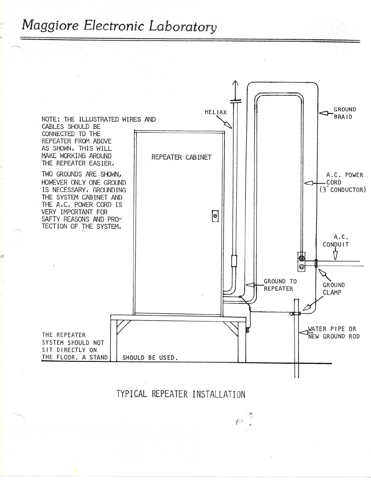
NOTE: THE ILLUSTRATED WIRES AND
CABLES SllouLD BE
CONNECTED TO THEREPEATERFRCMABOVEAssrowN,THlswlLLRAKEWORKINGAROUNDTHEREPEATEREASIER,i"OGROuNDsAREsroIN,
REPEATER CABINET E
rowEVER owLy ONE GRouND
CORD
IS NECESSARY. GROUNDINGTHESYSTEMCABINETANDTHEA,C,POWERCORDISVERYIMPORTANTFORSAFTYREASONSANDPRO-TECTIONOFTHESYSTEM,
( 3-CONDUCTORA.C.c0N6uIT
WANE
\GROUNDCLAMPERPIPE 0RGROUNDROD
.
THE REPEATERSYSTEMSHOULD NOTSITDIRECTLYONI_HEFLOOR.ASTAND
SHOULD BE USED.
TYPICAL REPEATER INSTALLATION
Table of contents


