GMI D5072S-096 User manual

D5072-096 - SIL 2 Thermocouple/mV Repeater G.M. International ISM0388-4
SIL 2 Thermocouple/mV Repeater, DIN-Rail
Models D5072S-096, D5072D-096
D5072S-096 - D5072D-096
INSTRUCTION MANUAL

D5072-096 - SIL 2 Thermocouple/mV Repeater G.M. International ISM0388-4
2
General Description:
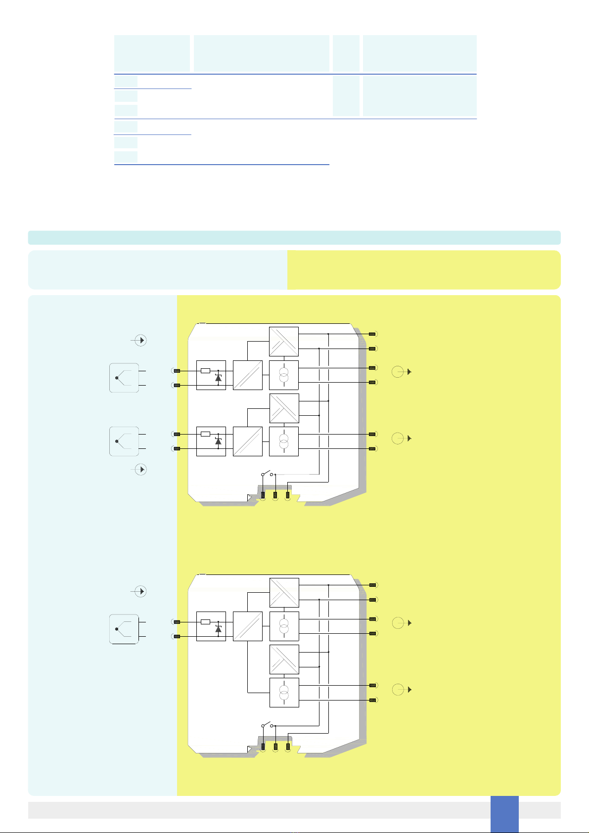
The single and dual channel Isolating Repeater D5072S-096 and D5072D-096
accepts a low level dc signal from millivolt or thermocouple sensor, located in Hazardous Area, and repeats, with isolation, the signal to Safe Area, suitable for applications requiring
SIL 2 (according to IEC 61508:2010) in safety related systems for high risk industries.
For D5072D-096 module: duplicator function provides two independent outputs from one single input.
Mounting on standard DIN-Rail, with or without Power Bus, in Safe Area / Non Hazardous Location or in Zone 2 / Class I, Division 2 or Class I, Zone 2.
Fault Detection:
D5072-096 module is able to detect the breakage of the sensor lines (Burnout), as well as internal unrecoverable module errors.
Functional Safety Management Certification:
G.M. International is certified by TUV to conform to IEC61508:2010 part 1 clauses 5-6 for safety related systems up to and included SIL3.
Technical Data
Characteristics
Supply: 24 Vdc nom (18 to 30 Vdc) reverse polarity protected,
ripple within voltage limits ≤5 Vpp, 2 A time lag fuse internally protected.
Current consumption @ 24 V: 35 mA.
Power dissipation @ 24 V: 0.85 W.
Isolation (Test Voltage): I.S. In/Out 2.5 KV; I.S. In/Supply 2.5 KV; I.S. In/I.S. In 500 V;
Out/Supply 500 V; Out/Out 500 V.
Input: millivolt or any type of thermocouple within Input Range.
Integration time: 75 ms (fast), 375 ms (slow), user selectable.
Resolution: 1 µV.
Input range: -10 to +100 mV.
Thermocouple burnout current: ≤50 µA.
Fault: Output reflects burnout/internal fault condition via highscale (+110 mV) value forcing. Fault condition is also signalled via BUS and red LED on front panel.
Output: millivolt.
Transfer characteristic: linear.
Response time: ≤20 ms (10 to 90 % step).
Output range: -10 to +100 mV.
Performance: Ref. Conditions 24 V supply, 23 ± 1 °C ambient temperature, slow integration mode.
Input: Calibration and linearity accuracy: ≤±10 µV.
Temperature influence: ≤±3 µV/°C, typical.
Output: Calibration and linearity accuracy: ≤±10 µV.
Temperature influence: ≤±3 µV/°C, typical.
Compatibility:
CE mark compliant, conforms to Directive:
2014/34/EU ATEX, 2014/30/EU EMC, 2014/35/EU LVD, 2011/65/EU RoHS.
Environmental conditions:
Operating: temperature limits – 40 to + 70 °C, relative humidity 95 %, up to 55 °C. Storage: temperature limits – 45 to + 80 °C.
Max altitude: 2000 m a.s.l.
Safety Description:
ATEX: II 3(1)G Ex ec [ia Ga] IIC T4 Gc, II (1)D [Ex ia Da] IIIC, I (M1) [Ex ia Ma] I
IECEx / INMETRO / NEPSI: Ex ec [ia Ga] IIC T4 Gc, [Ex ia Da] IIIC, [Ex ia Ma] I,
UL: NI / I / 2 / ABCD / T4, AIS / I, II, III / 1 / ABCDEFG, AEx nA [ia Ga] IIC T4 Gc
C-UL: NI / I / 2 / ABCD / T4, AIS / I, II, III / 1 / ABCDEFG, Ex nA [ia Ga] IIC T4 Gc X
EAC-EX: 2Ex nA [ia Ga] IIC T4 Gc X, [Ex ia Da] IIIC, [Ex ia Ma] I.
UKR TR n. 898: 2ExnAiaIICT4 X, ExiaI X
associated apparatus and non-sparking electrical equipment.
D5072S-096:Uo/Voc = 7.2 V, Io/Isc = 23 mA, Po/Po = 40 mW,
Ui/Vmax = 12.8 V, Ci = 0 nF, Li = 0 nH at terminals 7-8.
D5072D-096: Uo/Voc = 7.2 V, Io/Isc = 16 mA, Po/Po = 27 mW,
Ui/Vmax = 12.8 V, Ci = 0 nF, Li = 0 nH at terminals 7-8, 11-12.
Um = 250 Vrms or Vdc, -40 °C ≤Ta ≤70 °C.
Approvals:
BVS 12 ATEX E 053 X conforms to EN60079-0, EN60079-7, EN60079-11.
IECEx BVS 12.0050X conforms to IEC60079-0, IEC60079-7, IEC60079-11.
INMETRO DNV 13.0110 X conforms to ABNT NBR IEC60079-0, ABNT NBR IEC60079-11, ABNT NBR IEC60079-15, ABNT NBR IEC60079-26.
UL & C-UL E222308 conforms to UL913, UL 60079-0, UL60079-11, UL60079-15, UL121201 for UL
and CSA-E60079-0, CSA-E60079-11, CSA-E60079-15 and CSA-C22.2 No. 213 for C-UL.
C-IT.MH62.B.04182 conforms to GOST R IEC 60079-0,GOST R IEC 60079-11, GOST R IEC 60079-15.
CЦ16.0036 X conforms to ДСТУ 7113, ГОСТ 22782.5-78, ДСТУ IЕС 60079-15.
GYJ14.1406X conforms to GB3836.1, GB3836.4; GB3836.8, GB3836.20.
TÜV Certificate No. C-IS-722160171, SIL 2 conforms to IEC61508:2010 Ed.2 .
TÜV Certificate No. C-IS-236198-09, SIL 3 Functional Safety Certificate conforms to IEC61508:2010 Ed.2, for Management of Functional Safety.
Mounting:
EN/IEC60715 TH 35 DIN-Rail, with or without Power Bus.
Weight: about 135 g D5072D-096, 130 g D5072S-096.
Connection: by polarized plug-in disconnect screw terminal blocks to accommodate
terminations up to 2.5 mm2.
Location: installation in Safe Area/Non Hazardous Locations or Zone 2, Group IIC T4 or Class I, Division 2, Group A,B,C,D, T4 or Class I, Zone 2, Group IIC, T4.
Protection class: IP 20.
Dimensions: Width 12.5 mm, Depth 123 mm, Height 120 mm.
The module is fully programmable. Operating parameters can be changed from PC via PPC5092 adapter connected to USB serial line and SWC5090 software.
Measured values and diagnostic alarms can be read on both serial configuration or Modbus output line.
SWC5090 software also allows the Monitoring and Recording of values. For details please see SWC5090 manual ISM0154.
Programming
FSM
SIL 3

D5072-096 - SIL 2 Thermocouple/mV RepeaterG.M. International ISM0388-4 3
Ordering Information
Front Panel and Features
SIL 2 according to IEC 61508:2010 (Route 2H) with Tproof = 2 / 5 years (≤10% / >10 % of total SIF).
SC 3: Systematic Capability SIL 3.
Input from Zone 0 (Zone 20) / Division 1, installation in Zone 2 / Division 2.
mV or thermocouple Input Signal.
Output duplication possible for D5072D-096.
High Accuracy, µP controlled A/D converter.
Three port isolation, Input/Output/Supply.
EMC Compatibility to EN61000-6-2, EN61000-6-4, EN61326-1, EN61326-3-1 for safety system.
ATEX, IECEx, UL & C-UL, INMETRO, EAC-EX, UKR TR n. 898, NEPSI, TÜV Certifications.
TÜV Functional Safety Certification.
High Density, two channels per unit.
Simplified installation using standard DIN-Rail and plug-in terminal blocks, with or without Power Bus.
250 Vrms (Um) max. voltage allowed to the instruments associated with the barrier.
Data logging and monitoring via software.
+Input Ch1 for thermocouple TC or for millivolt source
Terminal block connections
HAZARDOUS AREA SAFE AREA
-Input Ch1 for thermocouple TC or for millivolt source
+Input Ch2 for thermocouple TC or for millivolt source
-Input Ch2 for thermocouple TC or for millivolt source
7
8
11
12
+Output Ch1
1
-Output Ch1
2
+Output Ch2
3
-Output Ch2
4
+Power Supply 24 Vdc
5
-Power Supply 24 Vdc
6
7 8
11 12
12
34
56
Power Bus and DIN-Rail accessories:
Connector JDFT049 Cover and fix MCHP196
Terminal block male MOR017 Terminal block female MOR022
Model: D5072
1 channel S
2 channels D
-096
SIL 2
5 6
2
4
1
3
7 8
1211
D5072
-096
CONFIG
PWR
FLT 1
FLT 2

D5072-096 - SIL 2 Thermocouple/mV Repeater G.M. International ISM0388-4
4
Parameters Table
Must
be
Hazardous Area/
Hazardous Locations
Device Parameters
D5072-096 Associated
Apparatus Parameters
Must
be
Hazardous Area/
Hazardous Locations
Device + Cable Parameters
Uo / Voc = 7.2 V Ui / Vmax
In the system safety analysis, always check the Hazardous Area/Hazardous Locations devices to conform with the related system documentation, if the device is Intrinsically Safe check
its suitability for the Hazardous Area/Hazardous Locations and group encountered and that its maximum allowable voltage, current, power (Ui/Vmax, Ii/Imax, Pi/Pi) are not exceeded
by the safety parameters (Uo/Voc, Io/Isc, Po/Po) of the D5072-096 series Associated Apparatus connected to it. Also consider the maximum operating temperature of the field device,
check that added connecting cable and field device capacitance and inductance do not exceed the limits (Co/Ca, Lo/La, Lo/Ro) given in the Associated Apparatus parameters for the
effective group. See parameters indicated in the table below:
D5072-096
Terminals
Ch1 7 - 8
D5072S-096
Ch1
Ch2
7 - 8
11 - 12
Io / Isc = 23 mA
Io / Isc = 16 mA
Po / Po = 40 mW
Po / Po = 27 mW
≤
Ii/ Imax≤
Pi / Pi
≤
D5072-096
Terminals
Ch1
Ch2
7 - 8
11 - 12
D5072-096 Associated Apparatus
Parameters Cenelec (US)
Ci / Ci device + C cable≥
IIC (A, B)
Co / Ca = 13.5 µF
Co / Ca = 240 µF
Co / Ca = 1000 µF
IIB (C)
IIA (D)
IIC (A, B)
Co / Ca = 13.5 µF
Co / Ca = 240 µF
Co / Ca = 1000 µF
IIB (C)
IIA (D)
Co / Ca = 1000 µF
Co / Ca = 240 µF
I
IIIC (E, F, G)
I
Co / Ca = 1000 µF
Co / Ca = 240 µF
Ch1 7 - 8
Li / Li device + L cable≥
IIC (A, B)
Lo / La = 67 mH
Lo / La = 268 mH
Lo / La = 537 mH
IIB (C)
IIA (D)
IIC (A, B)
Lo / La = 138 mH
Lo / La = 555 mH
Lo / La = 1111 mH
IIB (C)
IIA (D)
Lo / La = 882 mH
Lo / La = 268 mH
I
IIIC (E, F, G)
I
Lo / La = 1822 mH
Lo / La = 555 mH
Li / Ri device and
L cable / R cable
≥
IIC (A, B)
Lo / Ro = 875 µH/Ω
Lo / Ro = 3500 µH/Ω
Lo / Ro = 7000 µH/Ω
IIB (C)
IIA (D)
IIC (A, B)
Lo / Ro = 1290 µH/Ω
Lo / Ro = 5160 µH/ΩIIB (C)
IIA (D)
Lo / Ro = 11480 µH/Ω
Lo / Ro = 3500 µH/Ω
I
IIIC (E, F, G)
I
IIIC (E, F, G)
Lo / Ro = 16950 µH/Ω
Lo / Ro = 5160 µH/Ω
Lo / Ro = 10330 µH/Ω
IIIC (E, F, G)
IIIC (E, F, G)
D5072D-096
Ch1 7 - 8
D5072S-096
Ch1
Ch2
7 - 8
11 - 12
D5072D-096
Ch1 7 - 8
D5072S-096
Ch1
Ch2
7 - 8
11 - 12
D5072D-096
D5072S-096
D5072D-096
Ch1
Ch2
7 - 8
11 - 12
Ch1 7 - 8
D5072S-096
D5072D-096
Ch1
Ch2
7 - 8
11 - 12
Ch1 7 - 8D5072S-096
D5072D-096

D5072-096 - SIL 2 Thermocouple/mV RepeaterG.M. International ISM0388-4 5
When used with separately powered intrinsically safe devices, check that maximum allowable voltage, current (Ui/Vmax, Ii/Imax) of the D5072-096 Associated Apparatus are not
exceeded by the safety parameters (Uo/Voc, Io/Isc) of the Intrinsically Safe device, indicated in the table below:
For installations in which both the Ci and Li of the Intrinsically Safe apparatus exceed 1 % of the Co and Lo parameters of the Associated Apparatus (excluding the cable),
then 50 % of Co and Lo parameters are applicable and shall not be exceeded (50 % of the Co and Lo become the limits which must include the cable such that Ci device + C cable
≤50 % of Co and Li device + L cable ≤50 % of Lo). The reduced capacitance of the external circuit (including cable) shall not be greater than 1 μF for Groups I, IIA, IIB and 600 nF for
Group IIC.
If the cable parameters are unknown, the following value may be used: Capacitance 200 pF per meter (60 pF per foot), Inductance 1 µH per meter (0.20 µH per foot).
Must
be
Hazardous Area/
Hazardous Locations
Device Parameters
D5072-096 Associated
Apparatus Parameters
Ui / Vmax = 12.8 V Uo / Voc
D5072-096
Terminals
≥
Ci = 0 nF, Li= 0 nH
Function Diagram
HAZARDOUS AREA ZONE 0 (ZONE 20) GROUP IIC,
HAZARDOUS LOCATIONS CLASS I, DIVISION 1, GROUPS A, B, C, D,
CLASS II, DIVISION 1, GROUPS E, F, G, CLASS III, DIVISION 1,
CLASS I, ZONE 0, GROUP IIC
SAFE AREA, ZONE 2 GROUP IIC T4,
NON HAZARDOUS LOCATIONS, CLASS I, DIVISION 2,
GROUPS A, B, C, D T-Code T4, CLASS I, ZONE 2, GROUP IIC T4
Ch1 7 - 8
D5072S-096
Ch1
Ch2
7 - 8
11 - 12
D5072D-096
Ch1 7 - 8
D5072S-096
Ch1
Ch2
7 - 8
11 - 12
D5072D-096
==
=
5 +
6 -
1 +
2 -
3 +
4 -
7
12
MODEL D5072D-096
=
=
=
=
mV Out 1 (SIL 2)
11
8
+
-
F
Power and
Fault Bus
Supply 24 Vdc
mV Out 2 (SIL 2)
==
=
In 1
In 2
+
-
TC / mV
+
-
TC / mV
==
=
5 +
6 -
1 +
2 -
3 +
4 -
7
MODEL D5072D-096 (Duplicator)
=
=mV Out 1-A (SIL 2)
8
+
-
F
Power and
Fault Bus
Supply 24 Vdc
mV Out 1-B (SIL 2)
==
=
In 1
+
-
TC / mV

D5072-096 - SIL 2 Thermocouple/mV Repeater G.M. International ISM0388-4
6
Function Diagram
MODEL D5072S-096
+
-
F
Power and
Fault Bus
==
=
5 +
6 -
1 +
2 -
7
=
=mV Out 1 (SIL 2)
8
Supply 24 Vdc
In 1
+
-
TC / mV
HAZARDOUS AREA ZONE 0 (ZONE 20) GROUP IIC,
HAZARDOUS LOCATIONS CLASS I, DIVISION 1, GROUPS A, B, C, D,
CLASS II, DIVISION 1, GROUPS E, F, G, CLASS III, DIVISION 1,
CLASS I, ZONE 0, GROUP IIC
SAFE AREA, ZONE 2 GROUP IIC T4,
NON HAZARDOUS LOCATIONS, CLASS I, DIVISION 2,
GROUPS A, B, C, D T-Code T4, CLASS I, ZONE 2, GROUP IIC T4
D5072-096 series are isolated Intrinsically Safe Associated Apparatus installed into standard EN/IEC60715 TH 35 DIN‑Rail located in Safe Area or Zone 2, Group IIC, Temperature T4
or Class I, Division 2, Group A, B, C, D, T4 Hazardous Area within the specified operating temperature limits Tamb ‑40 to +70 °C, and connected to equipment with a maximum limit for
power supply Um of 250 Vrms or Vdc. Not to be connected to control equipment that uses or generates more than 250 Vrms or Vdc with respect to earth ground.
D5072-096 series must be installed, operated and maintained only by qualified personnel, in accordance to the relevant national/international installation standards (e.g. EN/
IEC60079‑14 Electrical apparatus for explosive gas atmospheres - Part 14: Electrical installations in hazardous areas (other than mines)), following the established installation rules,
particular care shall be given to segregation and clear identification of I.S. conductors from non I.S. ones.
De‑energize power source (turn off power supply voltage) before plug or unplug the terminal blocks when installed in Hazardous Area or unless area is known to be nonhazardous.
Warning: substitution of components may impair Intrinsic Safety and suitability for Zone 2.
Explosion Hazard: to prevent ignition of flammable or combustible atmospheres, disconnect power before servicing or unless area is known to be nonhazardous.
Failure to properly installation or use of the equipment may risk to damage the unit or severe personal injury.
The unit cannot be repaired by the end user and must be returned to the manufacturer or his authorized representative. Any unauthorized modification must be avoided.
Warning
Operation
Each input channel of Temperature Signal Converter D5072-096 accepts a low level dc signal from millivolt or thermocouple sensor, located in Hazardous Area, and repeats, with
isolation, the signal to Safe Area.
Presence of supply power is displayed by a “POWER ON” green signaling LED; integrity of field sensor and connecting line can be monitored by a configurable burnout circuit which, if
enabled, can drive output signal to upscale or downscale limit. Burnout condition is signaled by red front panel LED for each channel.
D5072D-096 module has double input and output channel, and can also be programmed to interface a single input and obtain dual output channel (duplicator).
Installation
D5072-096 series are Temperature Signal Converter housed in a plastic enclosure suitable for installation on EN/IEC60715 TH 35 DIN-Rail, with or without Power Bus.
D5072-096 series can be mounted with any orientation over the entire ambient temperature range.
Electrical connection are accommodated by polarized plug-in removable screw terminal blocks which can be plugged in/out into a powered unit without suffering or causing any damage
(for Zone 2 installations check the area to be nonhazardous before servicing). Connect only one individual conductor per each clamping point, use conductors up to 2.5 mm²
(13 AWG) and a torque value of 0.5‑0.6 Nm. Use only cables that are suitable for a temperature of at least 85°C.The wiring cables have to be proportionate in base to the current and
the length of the cable.
In case of installation in zone 2, the connecting cables of non-intrinsically safe circuits must be safely routed in a cable duct or similar. The distance between the pluggable connection
terminal and the cable duct should not exceed 500 mm cable length.
On the section “Function Diagram” and enclosure side a block diagram identifies all connections.
Intrinsically Safe conductors must be identified and segregated from non I.S. and wired in accordance to the relevant national/international installation standards (e.g. EN/IEC60079-14
Electrical apparatus for explosive gas atmospheres - Part 14: Electrical installations in hazardous areas (other than mines)), make sure that conductors are well isolated from each other
and do not produce any unintentional connection.
The enclosure provides, according to EN60529, an IP20 minimum degree of protection (or similar to NEMA Standard 250 type 1). The equipment shall only be used in an area of at least
pollution degree 2, as defined in IEC 60664-1. When installed in EU Zone 2, the unit shall be installed in an enclosure that provides a minimum ingress protection of IP54 in accordance
with IEC 60079-0. When installed in a Class I, Zone 2 Hazardous Location, the unit shall be mounted in a supplemental AEx or Ex enclosure that provides a degree of protection not less
than IP54 in accordance with UL/CSA 60079-0. When installed in a Class I, Division 2 Hazardous Location, the unit shall be mounted in a supplemental enclosure that provides a degree
of protection not less than IP54. The enclosure must have a door or cover accessible only by the use of a tool. The end user is responsible to ensure that the operating temperature of
the module is not exceeded in the end use application.
Units must be protected against dirt, dust, extreme mechanical (e.g. vibration, impact and shock) and thermal stress, and casual contacts. If enclosure needs to be cleaned use only a
cloth lightly moistened by a mixture of detergent in water.
Electrostatic Hazard: to avoid electrostatic hazard, the enclosure of D5072-096 must be cleaned only with a damp or antistatic cloth.
Any penetration of cleaning liquid must be avoided to prevent damage to the unit. Any unauthorized modification must be avoided.
D5072-096 series must be connected to SELV or PELV supplies.
All circuits connected to D5072-096 series must comply with the overvoltage category II (or better) according to EN/IEC60664-1.
Start-up
Before powering the unit check that all wires are properly connected, particularly supply conductors and their polarity, input and output wires, also check that Intrinsically Safe conductors
and cable trays are segregated (no direct contacts with other non I.S. conductors) and identified either by color coding, preferably blue, or by marking.
Check conductors for exposed wires that could touch each other causing dangerous unwanted shorts.
Check that the module has been correctly configured through SWC5090 software. For details please see SWC5090 manual ISM0154.
Turn on power, the “power on” green LED must be lit, output on each channel must be in accordance with the corresponding input signal value and input/output chosen transfer function.
If possible change the sensor condition and check the corresponding Safe Area output.

D5072-096 - SIL 2 Thermocouple/mV RepeaterG.M. International ISM0388-4 7
Input specifications
Input specifications:
Notes:
TC/mV Accuracy shown in slow acquisition mode, after calibration.
Input Type Standards Min Span
[°C (°F)] Accuracy
[°C (°F)] Accuracy Range
[°C (°F)] Maximum Range
[°C (°F)] Temperature Influence
per °C typical [°C (°F)]
TC
A1 GOST 8.585 150 (270) ±0.7 (±1.3) 0 to 2500
(32 to 4532) 0 to 2500
(32 to 4532) ≤±0.090
(≤±0.162)
A2 GOST 8.585 100 (180) ±0.5 (±0.9) 0 to 1800
(32 to 3272) 0 to 1800
(32 to 3272) ≤±0.050
(≤±0.090)
A3 GOST 8.585 100 (180) ±0.5 (±0.9) 0 to 1800
(32 to 3272) 0 to 1800
(32 to 3272) ≤±0.050
(≤±0.090)
B IEC 60584
GOST 8.585
ASTM E230 200 (360) ±1.1 (±2.0) 450 to 1820
(842 to 3308) 0 to 1820
(32 to 3308) ≤±0.060
(≤±0.108)
C ASTM E230
ASTM E988 100 (180) ±0.6 (±1.1) 0 to 2315
(32 to 4199) 0 to 2315
(32 to 4199) ≤±0.080
(≤±0.144)
D ASTM E988 100 (180) ±0.6 (±1.1) 0 to 2315
(32 to 4199) 0 to 2315
(32 to 4199) ≤±0.080
(≤±0.144)
E IEC 60584
GOST 8.585
ASTM E230 50 (90) ±0.2 (±0.4) -150 to 1000
(-238 to 1832) -270 to 1000
(-454 to 1832) ≤±0.050
(≤±0.090)
J IEC 60584
GOST 8.585
ASTM E230 50 (90) ±0.2 (±0.4) -150 to 1200
(-238 to 2192) -210 to 1200
(-346 to 2192) ≤±0.050
(≤±0.090)
K IEC 60584
GOST 8.585
ASTM E230 50 (90) ±0.3 (±0.5) -150 to 1372
(-238 to 2502) -270 to 1372
(-454 to 2502) ≤±0.050
(≤±0.090)
L (type “L” DIN) DIN 43710 50 (90) ±0.2 (±0.4) -200 to 900
(-328 to 1652) -200 to 900
(-328 to 1652) ≤±0.050
(≤±0.090)
LR (type “L” GOST) GOST 8.585 50 (90) ±0.3 (±0.5) -200 to 800
(-328 to 1472) -200 to 800
(-328 to 1472) ≤±0.050
(≤±0.090)
N IEC 60584
GOST 8.585
ASTM E230 50 (90) ±0.4 (±0.7) -150 to 1300
(-238 to 2372) -270 to 1300
(-454 to 2372) ≤±0.060
(≤±0.108)
R IEC 60584
GOST 8.585
ASTM E230 150 (270) ±0.8 (±1.4) 50 to 1768
(122 to 3214) -50 to 1768
(-58 to 3214) ≤±0.060
(≤±0.108)
S IEC 60584
GOST 8.585
ASTM E230 150 (270) ±0.8 (±1.4) 50 to 1768
(122 to 3214) -50 to 1768
(-58 to 3214) ≤±0.060
(≤±0.108)
T IEC 60584
GOST 8.585
ASTM E230 50 (90) ±0.2 (±0.4) -100 to 400
(-148 to 752) -270 to 400
(-454 to 752) ≤±0.020
(≤±0.036)
U DIN 43710 50 (90) ±0.4 (±0.7) -200 to 600
(-328 to 1112) -200 to 600
(-328 to 1112) ≤±0.040
(≤±0.072)
Type Min Span
[mV] Accuracy
[µV] Accuracy Range
[mV] Maximum Range
[mV] Temperature Influence
per °C typical [µV]
mV DC standard 1 ±10 -10 to 80 -10 to 100 ≤±3
This manual suits for next models
1
Table of contents
Other GMI Repeater manuals