manuals.online logo
Brands
  1. Home
  2. •
  3. Brands
  4. •
  5. Meler
  6. •
  7. Water Pump
  8. •
  9. Meler Micron PUR LC User manual

Meler Micron PUR LC User manual

QUICK START GUIDE: MICRON PUR
Warning: Risk of electrical shock. Carelessness may produce injury or death.
Warning: Hot zone with high temperatures. Risk of burns. Use thermal
protective equipment.
Warning: System under pressure. Risk of burns or particle projection. Use
thermal protective equipment and googles.
Warning: Important information for the correct use of the system. May include
one or several of the previous hazards, and therefore must be kept in mind to
avoid damage and injury.
Components, options and accessories
Electrical power connection Electrical power connection
Warning: The Micron PUR melters are equipment with current technology and with certain
foreseeable risks. Therefore, only allow qualified personnel with sufficient training and
experience to use, install or repair this equipment.
In case of doubts in the moment of installation, refer to the corresponding instructions
manual.
If you want this guide in other language, see the website:
http://www.meler.eu
Fitting straight short
Warning light
By-pass valve
Air dryer system
Hose
MODEL No. OUTPUT 1 PHASE 3 PHASES
230 VAC 400 VAC Y
1 PUMP 2 PUMPS 1 PUMP 2 PUMPS
Micron PUR LC 2 25.39 A 31.21 A 12.89 A 16.70 A
4 35.83 A 41.64 A 12.89 A 21.91 A
6 46.26 A - 17.28 A -
Micron PUR MC 2 39.43 A 44.25 A 16.52 A 16.70 A
4 48.86 A 54.69 A 21.74 A 21.91 A
6 59.30 A - 26.96 A -
1
3
L3 N PE L1 L2 L3 N PE
LN ~ 230V 50 Hz + PE 3N ~ 400/230V 50 Hz + PE
Pneumatic and hose connection
Low level detector
Wheels
LN ~ 230V 50 Hz + PE
3N ~ 400/230V 50 Hz + PE
2
Ø6-12mm
Mounting the equipment
Dimensions/ Free space
ITEM DESCRIPTION DIMENSION
A EQUIPMENT LENGTH LC 730mm
MC 740mm
B EQUIPMENT WIDTH LC 420mm
MC 520mm
C EQUIPMENT HEIGHT LC 630mm
MC 870mm
D EQUIPMENT HEIGHT WITH LID OPEN LC 910mm
MC 1215mm
E EQUIPMENT LENGTH WITH ELECTRICAL CABINET OPEN LC 920mm
MC 990mm
LENGTH OF THE EQUIPMENT WITH BRACKET FOR
ELECTRIC CABINET VARIABLE FREQUENCY DRIVES IN
LOWERED POSITION
LC 1280mm
MC 1355mm
ITEM MICRON LC MICRON MC
A 96 mm 96 mm
B 377,5 mm 529,5
C 569,5 mm 721,5 mm
D 75 mm 75 mm
E 328,5 mm 422,5 mm
F 15 mm 15 mm
G 13 mm 13 mm
M8
M8
Nota: To calculate the space necessary to install the equipment in terms of its length, you must
add at least 280 mm to the measurements indicated in the table in order to be able to open the
distributor’s purger access door.
E
A
C
D
B
APROBACION
Ing. FabricaciónCalidad Producción
Nombre:
Nombre: Nombre:
MANTENER ORDEN Y LIMPIEZA
EN EL PUESTO Y
EN LA LINEA EN GENERAL
GUANTESZAPATOS GAFAS OTROS
EQUIPO
DE SEGURIDAD
Formación requerida
operario
Nºde Pokayokes
Piezas en proceso
Calibración requerida
328,5
654,5
13
15
96 462,5
Ø9
75
A B
G
F
E
D
C
Air dryer connection
Charge of adhesive
Micron PUR LC
2
Outer lid
Air-tight lid
3
1
Micron PUR MC
Outer lid
Air-tight lid
2
1
3
1 3 5
246
P= 0 bar 1
4
3
9/16“
6 x
3
Ø6mm
Pmax= 6 bar 2
Ø6mm
Pmax= 6 bar
Meler Gluing Solutions, S.A
P.I. Los Agustinos, calle G, nave D-43
E - 31160 ORCOYEN Navarra (España)
Tel.: + 34 948 351 110
Fax: + 34 948 351 130
e-mail: info@meler.eu
www.meler.eu
GLUING SOLUTIONS
MA-5097-ENG V0915
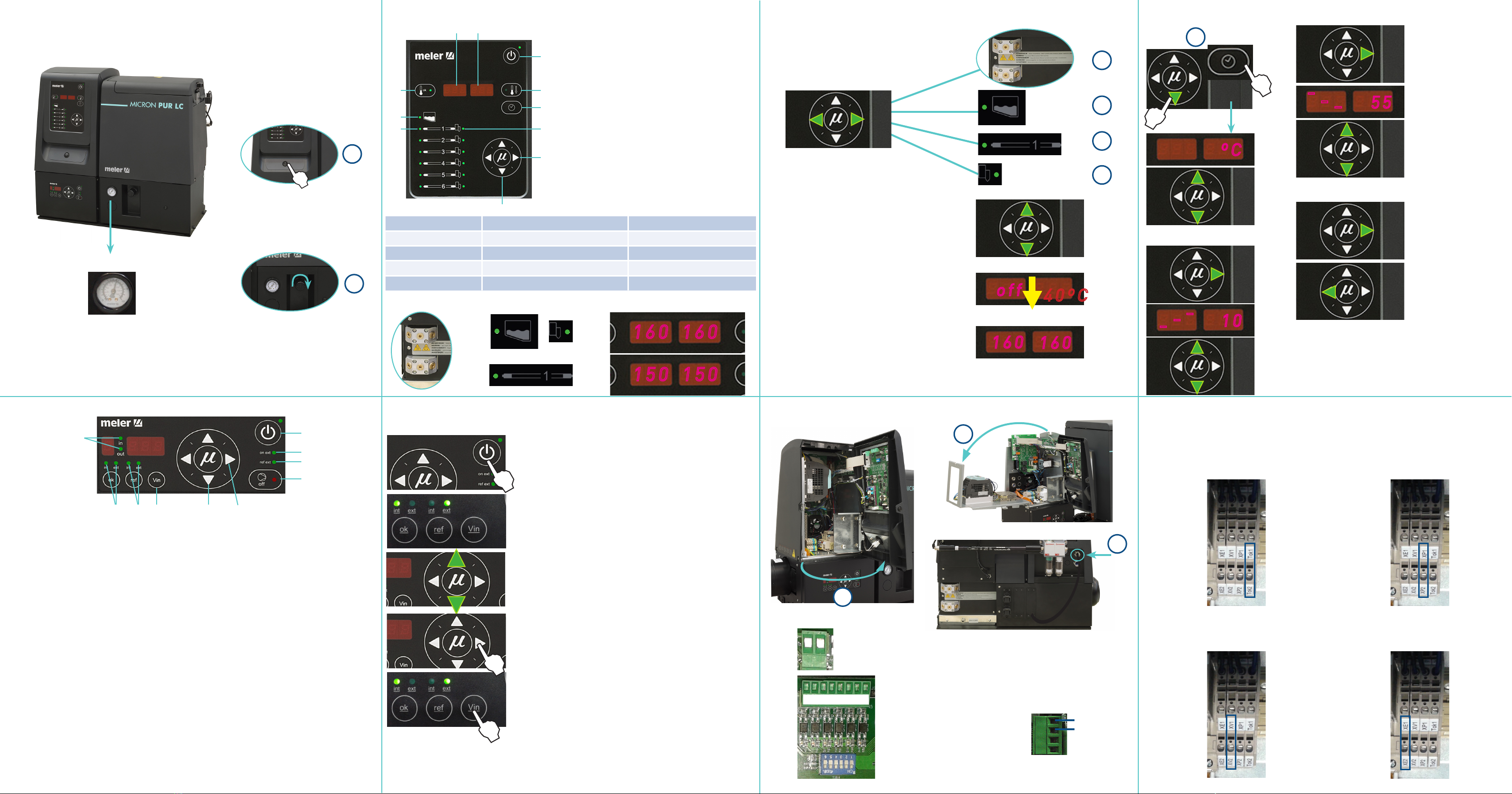
Control card Selecting the overheating value/ Standby
Temperature adjustment
External I/O connections (optional) External I/O connections (optional)
For each following signals, connect each wire in the terminals indicated:
Starting up the melter equipment
8
1
2
11
9
3
10
7
6
4 5
1. Tank indicator LED
2. Hose indicator LED
3. Gun indicator LED
4. Temperature set point
5. Actual temperature
6. ON/OFF switch
7. Standby function
8. Temperature OK LED and active pump
9. Time scheduling
10. Left/right button - channel selection
11. Up/down button - temperature modification
1. Control card ON/OFF LED.
2. Pumping ON/OFF LED.
3. Internal and external (ok) LEDs.
4. Internal and external (ref) LEDs.
5. On ext LED (external start-stop).
6. Ref ext LED (external reference).
7. In/Out LED to program the speed ramp.
8. Voltage value display.
9. Up/down arrow keys for selecting values.
10. Left/right arrow keys for selecting options.
To start working, select the appropriate mode of operation:
1. Internal pumping and speed control.
2. Internal pumping control and external speed control.
3. External pumping control and internal speed control.
4. External pumping and speed control.
To activate the start-up status, all of the following conditions must be met:
1. The equipment temperature is OK.
2. That pumping is enabled (red LED is turned off).
3. If the external ‘ok’ mode (start-stop) is selected, the external ‘ok’ input (E3) must be activated.
4. The failure input is not activated. For more information about the different functions of the pump control card, refer to the
corresponding instructions manual.
160160
150150
Select the element
Modify temperature
Below of 40ºC, temperature
display and heating OFF
Tank’s set point Tª value by default
3
1
2
4
off
40ºC
160
160
-
--
55
-
--
10
ºC
Return to initial
parameter
Next display to record the
value
Next display to record the
value:
1
OVERHEATING
10< Increase Tª < 25
STANDBY
25<Decrease Tª %< 55
CN 1
Power card
LOW LEVEL
1
2
1 contact NO
2 contact NO
Default values
1
2
Pump control card Speed working adjustment
Temperature OK
Since this contact is not under voltage, there is no
connection polarity.
Motor speed set point (ref ext)
The positive signal wire must be connected to point XV2 of
the terminal, while the negative wire must be connected
to point XV1.
Motor start up (ok ext)
Since this contact is not under voltage, there is no
connection polarity.
Failures output in pump control card
Since this contact is not under voltage, there is no
connection polarity.
1
5
6
2
4 8 9 103
71. Press the ON/OFF button to light up the control card.
2. Select the pumping mode ‘ok’ and the speed control ‘ref’.
In case of internal speed control, using the up/down arrows,
select the rotation speed.
3. The selected value is set pressing the right arrow key after
blinking three times.
In case of external speed control, the system will wait for the
speed signal from the main machine. Keeping the ‘Vin’ key
pressed will show the voltage sent by the main machine.
LED DISPLAY COMPONENT HEATING COMPONENT STATUS
constantly lit constant low temperature
blinking slowly as need (according to PID parameters) temperature near set point
blinking rapidly programming or display change in set point values
off not heating temperature reached
For more information about the different functions of the control card, refer to the
corresponding instructions manual.
On/ Off
1
2
P pneumatic P hydraulic
Ratio 1:15
3
Ø4-8mm
CN 5 CN 4
Control card
contact NO
contact NO
STANDBY
1 common and voltage out +
2 input for inhibitor output 1
3 input for inhibitor output 2
4 input for inhibitor output 3
5 input for inhibitor output 4
6 input for inhibitor output 5
7 input for inhibitor output 6
8 without connection
OUTPUT DISABLED
8 7 6 5 4 3 2 1

Other manuals for Micron PUR LC

1

This manual suits for next models

1

Other Meler Water Pump manuals

Meler Micron 5 User manual

Meler

Meler Micron 5 User manual

Meler Micron 5 User manual

Meler

Meler Micron 5 User manual

Popular Water Pump manuals by other brands

Teral LPWE-GS instruction manual

Teral

Teral LPWE-GS instruction manual

Hozelock Cyprio EasyClear 9000 Installation and operating instructions

Hozelock Cyprio

Hozelock Cyprio EasyClear 9000 Installation and operating instructions

Tuthill SOTERA 400B Series Owner’s Operation and Safety Manual

Tuthill

Tuthill SOTERA 400B Series Owner’s Operation and Safety Manual

LEYBOLD Sogevac NEO D 16 Original instruction manual

LEYBOLD

LEYBOLD Sogevac NEO D 16 Original instruction manual

Xylem LOWARA F 1-2 Operating and maintenance instructions

Xylem

Xylem LOWARA F 1-2 Operating and maintenance instructions

Pfeiffer Vacuum UNO 35 operating instructions

Pfeiffer Vacuum

Pfeiffer Vacuum UNO 35 operating instructions

TotalPond MD11400ASL manual

TotalPond

TotalPond MD11400ASL manual

Cembre B68M-P18-KV-RC1 Operation and maintenance instruction manual

Cembre

Cembre B68M-P18-KV-RC1 Operation and maintenance instruction manual

Walchem EZ Series instruction manual

Walchem

Walchem EZ Series instruction manual

Pfeiffer Vacuum A3P Series operating instructions

Pfeiffer Vacuum

Pfeiffer Vacuum A3P Series operating instructions

Grundfos SP14-27 Installation and operating instructions

Grundfos

Grundfos SP14-27 Installation and operating instructions

BJM Pumps SKG FAHRENHEIT Series Installation, operation & maintenance manual

BJM Pumps

BJM Pumps SKG FAHRENHEIT Series Installation, operation & maintenance manual

TECHCON TS8100 Series user guide

TECHCON

TECHCON TS8100 Series user guide

Stocker 301 user manual

Stocker

Stocker 301 user manual

Graco Series A Instructions-parts list

Graco

Graco Series A Instructions-parts list

Tecsis C1351X085005 operating manual

Tecsis

Tecsis C1351X085005 operating manual

STA-RITE PEXYD-133L owner's manual

STA-RITE

STA-RITE PEXYD-133L owner's manual

Crivit 273721 Instructions for use

Crivit

Crivit 273721 Instructions for use

manuals.online logo
manuals.online logoBrands
  • About & Mission
  • Contact us
  • Privacy Policy
  • Terms and Conditions

Copyright 2025 Manuals.Online. All Rights Reserved.