Memorex MLT2022SM User manual

Index of content
Copyright©2005 Aplus Technic® All Rights Reserved
1
1.Speacifi cations ........................................ 2
1.1 TV System ......................................... 2
1.1.1 Introduction .................................. 2
1.1.2 Key Features ............................... 2
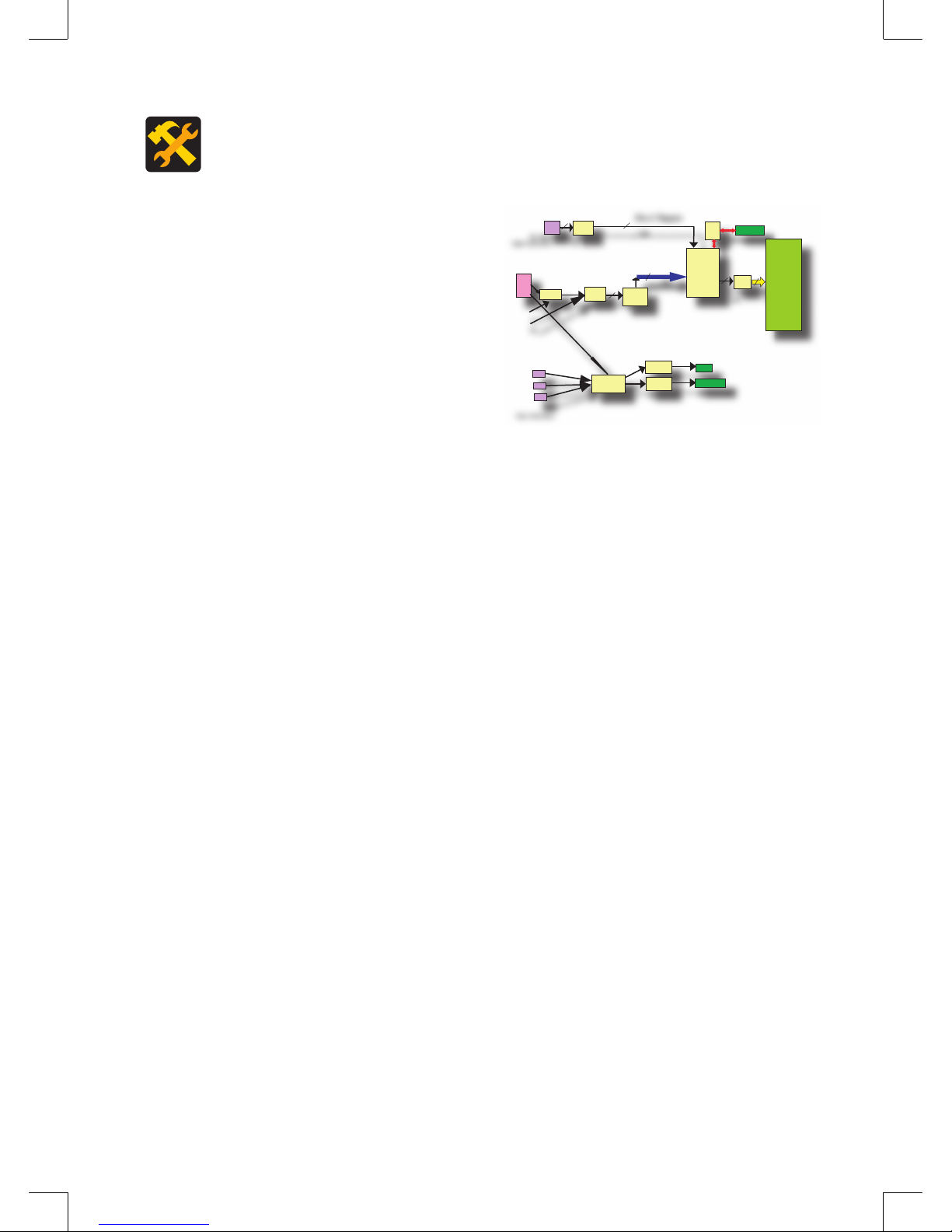
1.1.3 System Diagram .......................... 3
1.2 Panel speacifi cations ......................... 3
1.2.1 General spec brief ....................... 3
1.2.2 Optical spec brief ......................... 4
1.3 I/O interface ....................................... 5
1.3.1 Overview ..................................... 5
1.3.2 Video Functionality ...................... 6
1.3.3 Audio Functionality ...................... 6
1.3.4 Top keypad .................................. 6
1.4. Power ............................................... 7
1.4.1 External power supply ................. 7
1.4.2 Power switch ............................... 7
1.4.3 Power state ................................. 7
1.4.4 Working environment .................. 7
1.5. Channel management ...................... 7
1.5.1 Air/CATV ...................................... 7
1.5.2 Close Caption/ Vchip ................... 8
1.5.3 Miscellaneous .............................. 8
1.6. Safety & EMI test .............................. 8
1.6.1 Safety .......................................... 8
1.6.2 EMI .............................................. 8
1.7. Appearance & Carton ....................... 8
1.7.1 LCD TV dimension ..................... 8
1.7.2 Package dimension ..................... 8
1.7.3 Weight ......................................... 9
1.7.4 Packing detail .............................. 9
1.8. Reliability test ................................. 10
1.8.1 Temperature test ....................... 10
1.8.2 Humidity test .............................. 10
1.8.3 Thermal shock test .................... 10
1.8.4 Non Operating Random Vibration Test
(Packaged) ......................................... 10
1.8.5 Packing Drop Test ..................... 10
2.Drawing ................................................. 11
3.Dis-Assembly & Assembly ..................... 13
3.1.Stand .............................................. 13
3.2.Stand bracket ................................. 13
3.3.Back cover ...................................... 13
3.4.Keypad wire .................................... 13
3.5.VGA screws .................................... 14
3.6.I/O and EMI meael screws ............. 14
3.7.EMI metal ....................................... 14
3.8.Front cover ..................................... 14
3.9.Main board ..................................... 15
3.10.Inverter PCB ................................. 15
3.11.Panel high-voltage cables ............ 15
3.12.LCD metal .................................... 15
Pass the cables ..................................... 15
3.13.Top keypad ................................... 16
3.14.Keypad semi kit fi xture ................. 16
3.15.Speakers ...................................... 16
4.FAULT FINDING TREE ......................... 17
Main page of fault fi nding tree ............... 17
Power supply repair fl owchart ............... 18
OSD display repair fl owchart ................. 19
PC mode repair fl owchart ...................... 20
TV mode repair fl owchart ...................... 21
AV, SV and YCbCr/ YPbPr mode repair
fl owchart ................................................ 22
Audio repair fl owchart ............................ 23
5.SDK BOM .............................................. 24
SV
VGA INPUT D_Sub
JACK 3bit
24bit
24bit
24bit
YCbCr / YPbPr INPUT
YCbCr / YPbPr INPUT
Tuner
BOX
VChip
Close Caption
8bit 8bit
Video
Decoder1 De-Interlace
ADC
Decoder
Audio
Processor
A port
B port
RA port
MCU
Video Image
Processor
LVDS
IC
Audio
Amplifier
Headphone
Driver
AV
SV
Keypad & IR
Speaker
Earphone Jack
Circuit Diagram
PANEL
VGA
AV

1.Speacifi cations
Copyright©2005 Aplus Technic® All Rights Reserved
2
1.Speacifi cations
1.1 TV System
1.1.1 Introduction
Aplus LM/LT series products are cutting-edge LCD TVs. Basing on advanced image
processing technology and highly integrated circuit design, LM/LT series bring digital
multimedia entertainment from theater to your home. This document is the detail
spec of these optimized LCD TVs. We will define each sub-system except panel
spec & inspection in detail. Panel spec & inspection standards aren’t included in
main content of this document, see attached files.
1.1.2 Key Features
■ Ultra wide viewing angle-Super MVA technology
■ Wide viewing angel: Horizontal 160° /Vertical 140° (CR>=10)
■ HDTV Ready supported (480i/480p/1080i/720p)
■ Automatic 3:2 pull-down & 2:2 pull-down detection and recovery
■ 4:3/16:9/Anamorphic/Panorama aspect ratio
■ MTS supported
■ High brightness 450 nits
■ High contrast ratio 450:1
■ Fast response time 16ms
■ VGA (640x480 pixels) resolution
■ Auto-tune image optimization for VGA
■ Automatic VGA display mode detection & switching control
■ 3-D motion adaptive video de-interlace function
■
sRGB compliance allows end-user to experience the same colors as viewed on CRTs
■ Enhanced 3D noise reduction
■ Support YCbCr/YPbPr through VGA port.
■ Smart Theme functions (Rich, Multimedia, Nature, Soft)
■ Sound Theme functions (POP, Classic, Voice, Jazz, Flat)
■ Audio setup functions (L/R Balance, 5 band Equalizer)
■ 3 steps brightness control
■ Easy access top keypad controls (Menu, Volume up/down, CH up/down, Power)
■ Bundled 2W(max) x 2 stereo speaker
■ Built-in audio amplifier (2W×2)
■ Wall-mountable design.

3
1.Speacifi cations
Copyright©2005 Aplus Technic® All Rights Reserved
1.Speacifi cations
1.1.3 System Diagram
1.2 Panel speacifications
1.2.1 General spec brief
SV
VGA INPUT D_Sub
JACK 3bit
24bit
24bit
24bit
YCbCr / YPbPr INPUT
YCbCr / YPbPr INPUT
Tuner
BOX
VChip
Close Caption
8bit 8bit
Video
Decoder1 De-Interlace
ADC
Decoder
Audio
Processor
A port
B port
RA port
MCU
Video Image
Processor
LVDS
IC
Audio
Amplifier
Headphone
Driver
AV
SV
Keypad & IR
Speaker
Earphone Jack
Circuit Diagram
PANEL
VGA
AV
Item Specification Unit
Active Area 408 (H) x 306 (V) (20.1” diagonal) mm
Bezel Opening Area 412 (H) x 310 (V) mm
Driver Element a-si TFT active matrix - -
Pixel Number 640 x R.G.B. x 480 pixel -
Pixel Pitch 0.6375 (H) x 0.6375 (V) mm -
Pixel Arrangement RGB vertical stripe - -
Display Colors 16.7M color -
Display Operation Mode Transmissive mode / Normally white - -
Surface Treatment Anti-reflective coating + Anti-glare coating - -

1.Speacifi cations
Copyright©2005 Aplus Technic® All Rights Reserved
4
1.Speacifi cations
1.2.2 Optical spec brief
Item Symbol Condition Min. Typ. Max. Unit Note
Contrast Ratio CR - (450) - - Note(2)
TR - (5) - ms
Response Time TF - (11) - ms Note(3)
Center Luminance of White LCTBD (450) - cd/m2 Note(4)
Average Luminance of White LAVE TBD TBD - cd/m2
White Variation δW- - 1.6 - Note(7)
Cross Talk CT - - 4 % Note(5)
Rx (0.610) (0.640) (0.670) -
Red Ry (0.300) (0.330) (0.360) -
Gx (0.243) (0.273) (0.303) -
Green Gy (0.570) (0.600) (0.630) -
Bx (0.112) (0.142) (0.172) -
Blue By (0.040) (0.070) (0.100) -
Note(6)
Wx 0.255 0.285 0.315 -
White Wy 0.263 0.293 0.323 - 9, 300K
Color
Chromaticity
Color Gamut
θx=0°,θY =0°
Viewing Normal Angle
(75) %
θx+ (80) -
Horizontal θx- (80) -
θY+ (75) -
Viewing
Angle Vertical θY-
CR≥10
(65) -
Deg. Note(1)
Note (1) Definition of Viewing Angle (θx, θy):
Note (2) Definition of Contrast Ratio (CR):
The contrast ratio can be calculated by the following expression.
Contrast Ratio (CR) = L255 / L0
L255: Luminance of gray level 255
L 0: Luminance of gray level 0
CR = CR (5)
CR (X) is corresponding to the Contrast Ratio of the point X at the figure in Note (7).
Note (3) Definition of Response Time (TR, TF):
12 o’clock direction
θy+ = 90º
6 o’clock
θy- = 90º
θx−
θx+
θy- θy+
x- y+
y- x+
Normal
θx = θy = 0º
θX+ = 90º
θX- = 90º
Optical
Response
100%
90%
10%
0%
Gray Level 255
Gray Level 0
Gra
y
Level 255
T
ime
TRTF
Note (4) Definition of Luminance of White (LC, LAVE):
Measure the luminance of gray level 255 at center point and 5 points
LC = L (5)
LAVE = [L (1)+ L (2)+ L (3)+ L (4)+ L (5)] / 5
L (x) is corresponding to the luminance of the point X at the figure in Note (7).
Note (5) Definition of Cross Talk (CT):
CT = | YB – YA | / YA× 100 (%)
Where:
YA = Luminance of measured location without gray level 0 pattern (cd/m2)
YB = Luminance of measured location with gray level 0 pattern (cd/m2)
Note (6) Measurement Setup:
The LCD module should be stabilized at given temperature for 30 minutes to avoid abrupt
temperature change during measuring. In order to stabilize the luminance, the measurement
should be executed after lighting Backlight for 30 minutes in a windless room.
A
ctive Area
YA, U (D/2,W/8)
YA, R (7D/8,W/2)
YA, D (D/2,7W/8)
YA, L (D/8,W/2)
(0, 0)
(
D,W
)
Gray 128
A
ctive Area
Gray 0
(D/4,W/4)
(3D/4,3W/4)
(
0, 0
)
YB, U (D/2,W/8)
YB, R (7D/8,W/2)
YB, D (D/2,7W/8)
YB, L (D/8,W/2)
(
D,W
)
Gray 128
Photometer
(TOPCON BM-5A)
Field of View
= 2
º
500 mm
LCD Module
LCD Panel
Center of the Screen
Light Shield Room
(Ambient Luminance < 2 lux)
Gray 0
Note (7) Definition of White Variation (δW):
Measure the luminance of gray level 255 at 5 points
δW = Maximum [L (1), L (2), L (3), L (4), L (5)] / Minimum [L (1), L (2), L (3), L (4), L (5)]
D
W
Active Area
Vertical Line
Horizontal Line
: Test Point
X=1 to 5
5
1 2
3 4
D/4 D/2 3D/4
W/4
W/2
3W/4
X
Note (4) Definition of Luminance of White (LC, LAVE):
Measure the luminance of gray level 255 at center point and 5 points
LC = L (5)
LAVE = [L (1)+ L (2)+ L (3)+ L (4)+ L (5)] / 5
L (x) is corresponding to the luminance of the point X at the figure in Note (7).
Note (5) Definition of Cross Talk (CT):
CT = | YB – YA | / YA× 100 (%)
Where:
YA = Luminance of measured location without gray level 0 pattern (cd/m2)
YB = Luminance of measured location with gray level 0 pattern (cd/m2)
Note (6) Measurement Setup:
The LCD module should be stabilized at given temperature for 30 minutes to avoid abrupt
temperature change during measuring. In order to stabilize the luminance, the measurement
should be executed after lighting Backlight for 30 minutes in a windless room.
A
ctive Area
YA, U (D/2,W/8)
YA, R (7D/8,W/2)
YA, D (D/2,7W/8)
YA, L (D/8,W/2)
(0, 0)
(
D,W
)
Gray 128
A
ctive Area
Gray 0
(D/4,W/4)
(3D/4,3W/4)
(
0, 0
)
YB, U (D/2,W/8)
YB, R (7D/8,W/2)
YB, D (D/2,7W/8)
YB, L (D/8,W/2)
(
D,W
)
Gray 128
Photometer
(TOPCON BM-5A)
Field of View
= 2
º
500 mm
LCD Module
LCD Panel
Center of the Screen
Light Shield Room
(Ambient Luminance < 2 lux)
Gray 0

5
1.Speacifi cations
Copyright©2005 Aplus Technic® All Rights Reserved
1.Speacifi cations
1.3 I/O interface
1.3.1 Overview
RF TV Tuner input Slot x1 ...................................................................................1
Composite video + L / R (RCA) Audio input x1 ....................................................2
S-Video input (Audio shared with Composite input) ............................................3
Component video + L/R (RCA) Audio input x1 (for YCbCr/YPbPr) .....................4
15pin D-Sub VGA + earphone jack Audio input ...................................................5
Earphone Audio output x1 ...................................................................................6
DC input scoket and Power switch ......................................................................7

1.Speacifi cations
Copyright©2005 Aplus Technic® All Rights Reserved
6
1.Speacifi cations
1.3.2 Video Functionality
Terminal Type Impedance Audio Connector type Electric Characteristic
RF TV Tuner Input x 1 75 ohm Stereo L/R NTSC
■ AGC: 2.0-Vpp full-scale input, -6dB gain /
0.5Vpp full scale, +6dB gain.
■ Position: Back side
Composite Input x 1 75 ohm Stereo L/R
Video:
RCA (Yellow)
Audio:
RCA (R:Red,L:White)
■ PAL / NTSC auto detect
■ AGC: 2.0-Vpp full-scale input, -6dB gain /
0.5Vpp full scale, +6dB gain
■ Position: Back side
S-Video Input x 1 75 ohm Stereo L/R
Video:
Y/C Mini-Din
Audio:
Shared with Composite
■ PAL / NTSC auto detect
■ AGC: 2.0-Vpp full-scale input, -6dB gain /
0.5Vpp full scale, +6dB gain
■ Position: Back side
■ Shared with Composite
Component Input x 1 75 ohm Stereo L/R
Video:
RCA (Y: Green, Cb: Blue,
Cr: Red)
Audio:
RCA (R: Red, L: White)
■ AGC: 2.0-Vpp full-scale input, -6dB gain
/ 0.5Vpp full scale, +6dB gain for YCbCr
signal.
■ Support YCbCr/YPbPr signal (480i, 480p,
1080i, 720p).
■ Position: Back side
VGA Input x 1 75 ohm Stereo L/R
VGA:
15pin D-Sub (Blue)
Audio:
PC
Earphone 3.5φMini Jack x 1
■ Resolution mode auto detect.
■ RGB 0.7 Vp-p/75Ω, H/V sync 4.0 Vp-p/TTL
Polarity, Composite sync 4.0 Vp-p/TTL
Level, G sync 0.3 Vp-p/75 Ω Negative
Polarity
■ Position: Back side
1.3.3 Audio Functionality
Terminal Type Impedance Audio Connector type Electric Characteristic
Earphone Output x 1 32 ohm Stereo L/R Earphone 3.5φMini Jack
x 1
■ Volume adjustable by OSD.
■ Position: Back side
Speaker Output x 2 45 ohm Stereo L/R RCA x 2 (R:Red,
L:White)
■ Position: left & right hand side
■ Max output power: 2W
Internal
amplifier Output x 1 45 ohm Stereo L/R NA
■ Power: 2W
■ Frequency range: 100Hz ~ 20KHz
■ Position: Internal
1.3.4 Top keypad
Function Description
VOL- Decrease Volume/Left navigation key
MENU a. MENU –Display Main Menu b. ENTER –Confirm Function
VOL+ Increase volume/Right navigation key
POWER Power on or off
CH- Decrease TV channel/Down navigation key
CH+ Increase TV channel/Up navigation key

7
1.Speacifi cations
Copyright©2005 Aplus Technic® All Rights Reserved
1.Speacifi cations
1.4. Power
1.4.1 External power supply
Input: 100~240V AC, 50/60 Hz
Output: 12V DC/ 5A
Max power consumption: 60 W
1.4.2 Power switch
Primary main switch
Cut off power directly to make LCD TV shutdown completely.
Locate at the back side of LCD TV.
Standby switch
Turning off LCD panel & chipsets, go to power saving mode.
Locate ate the front keypad of LCD TV.
1.4.3 Power state
TV power on
LED status: Green
Power consumption: Max 60W
TV standby (Logical switch off)
Powered off by keypad or remote controller.
LED status: Red.
Power consumption: < 5 W
VGA standby mode.
LED status: Green
Power consumption: Max 30W
1.4.4 Working environment
Operating power voltage range: 90V ~ 264V AC
Operating temperature: 0oC ~ 40oC
Storage temperature: -10oC ~ 60oC
Operating ambient humidity: 5% ~ 93% RH
Storage humidity: 20% ~ 90% RH
1.5. Channel management
1.5.1 Air/CATV
Manual select Air/CATV for autoscan.
Auto detect IRC/HRC/STD
Build-in program table to accelerate autoscan speed.

1.Speacifi cations
Copyright©2005 Aplus Technic® All Rights Reserved
8
1.Speacifi cations
1.5.2 Close Caption/ Vchip
Support CC1/CC2/CC3/CC4/TT1/TT2/TT3/TT4 close option.
Support Vchip class option for TV-Y/ TV-Y7/ TV-G/ TV-PG/ TV-14/ TV-MA
Support Vchip MPAA option for MPAA-G/ MPAA-PG/ MPAA-PG13/ MPAA-R/
MPAA-NC17/ MPAA-X
Vchip default password: 3308
1.5.3 Miscellaneous
Max no of channel: 125
Channel AFT range: +1.0/-1.25MHz
1.6. Safety & EMI test
1.6.1 Safety
UL/cUL
UL60950, Third Edition (2000)
1.6.2 EMI
FCC
FCC Part 15, Subpart B, Class B
ANSI C63.4-2001
1.7. Appearance & Carton
1.7.1 LCD TV dimension (unit: mm)
510.4 (W).× 365 (H) × 183.54 (D) mm
For detail see the following session (2.Drawing).
1.7.2 Package dimension
680 (W) × 495 (H) × 215 (D) mm

9
1.Speacifi cations
Copyright©2005 Aplus Technic® All Rights Reserved
1.Speacifi cations
Die Cut
1.7.3 Weight
Net weight: 7 Kg (LCD TV only)
Gross weight: 8 Kg (include LCD TV & accessories)
Measurement: 2.7 CUFT, 0.08 CBM
1.7.4 Packing detail
LCD TV Unit
Accessories:
Power cord
Power adaptor
Remote Controller
Recyclable Battery (for remote controller) AAA x 2
User’s manual
Composite RCA cable (optional)
VGA cable (optional)
VGA audio input cable (optional)
680 mm
215 mm
495 mm

1.Speacifi cations
Copyright©2005 Aplus Technic® All Rights Reserved
10
1.Speacifi cations
1.8. Reliability test
Outsourcing tested by "Electronics Testing Center, Taiwan". (See: http://www.etc.org.
tw/default_en.htm)
1.8.1 Temperature test
Operating: 0 and 50oC for 96 hours
Storage: -10oC and 60oC for 96 hours
1.8.2 Humidity test
Operating: 40oC RH=93% for 96 hours
1.8.3 Thermal shock test
Operating: 10 cycles of TA = -10oC to TB = +60oC
Dwell time = exposure time = 30min, 10 cycles.
1.8.4 Non Operating Random Vibration Test (Packaged)
Frequency: 10~200Hz
Acceleration: 1.15gRMS
Time: Bottom 30 minutes, Top, Left, Right, Front, Back 10 minutes.
1.8.5 Packing Drop Test
Height: Corner , Faceand Edge 50 cm
1 Corners – 3 Edges – 6 Faces

2.Drawing
Copyright©2005 Aplus Technic® All Rights Reserved
2.Drawing
11

2.Drawing
2.Drawing
Copyright©2005 Aplus Technic® All Rights Reserved
12

3.Dis-Assembly & Assembly
Copyright©2005 Aplus Technic® All Rights Reserved
3.Dis-Assembly & Assembly
13
3.1.Stand Dis-assembly and Assembly
Refer to the picture at right side.
(No Screws need)
D1) Dis-assembly
Push the tenon (A) under stand base (B).
Pull the stand base () and then take it off.
A15)
Plug the tenon of bracket into stand base ().
3.3.Back cover Dis-assembly and Assembly
Refer to the picture at right side.(Torque: 4.5±0.5KG)
(P+3*10, 4 pcs)
D3) Dis-assembly
Take the screws (EA0305111) off.
Take the back cover () off.
A13) Assembly
Put the bcak cover() on.
Lock the screws (EA0305111) on.
3.2.Stand bracket Dis-assembly and Assembly
Refer to the picture at right side. (Torque: 4.5±0.5KG)
(, 3 pcs)
D2) Dis-assembly
Take the screws () off.
Take the stand bracket () off.
A14) Assembly
Put the stand bracket () on.
Lock the screws () on stand bracket.
3.4.Keypad wire Dis-assembly and Assembly
Refer to the picture at right side.
(No Screws need)
D4) Dis-assembly
Take the wire () off.
A12) Assembly
Plug the wire () on.

3.Dis-Assembly & Assembly
Copyright©2005 Aplus Technic® All Rights Reserved
14
3.5.VGA screws Dis-assembly and Assembly
Refer to the picture at right side. (Torque: 4.5±0.5KG)
(Hex Head pillar screw, 2 pcs)
D5) Dis-assembly
Take the 2 screws (EC0500781) off.
A11) Assembly
Lock the 2 screws (EC0500781) on.
3.7.EMI metal Dis-assembly and Assembly
Refer to the picture at right side. (Torque: 4.5±0.5KG)
(Π+3*4, 6 pcs)
D7) Dis-assembly
Take the 6 screws (EA1500611) off.
Take the EMI metal () off.
A9) Assembly
Put the EMI metal () on.
Lock the 6 screws (EA1500611) on EMI metal.
Note : EMI(Electromagnetic Interference)
3.8.Front cover Dis-assembly and Assembly
Refer to the picture at right side. (Torque: 4.5±0.5KG)
(P+3*8, 8 pcs)
D8) Dis-assembly
Take the 6 screws (EA0301511) off.
Take the front cover off.
A8) Assembly
Put the martix into front cover.
Lock the 6 screws (EA0301511) on the fornt cover.
3.6.I/O and EMI meael screws Dis-assembly
and Assembly
Refer to the picture at right side. (Torque: 2.5±0.5KG)
(P+2.6*8, 4 pcs)
D6) Dis-assembly
Take the 4 screws (EA0101011) off.
A10) Assembly
Lock the 4 screws (EA0301511) on.

3.Dis-Assembly & Assembly
Copyright©2005 Aplus Technic® All Rights Reserved
3.Dis-Assembly & Assembly
15
3.9.Main board Dis-assembly and Assembly
Refer to the picture at right side. (Torque: 4.5±0.5KG)
(P+3*6, 7 pcs)
D9) Dis-assembly
Take all the cables or wire off.
Take the 7 screws (EA0301211) off.
A7) Assembly
Lock the 7 screws (EA0301211) on.
Plug all the cables or wire in.
3.10.Inverter PCB Dis-assembly and Assembly
Refer to the picture at right side. (Torque: 4.5±0.5KG)
(P+3*6, 2 pcs)
D10) Dis-assembly
Take the high-voltage cables off .
Take the screws (EA0301211) off .
Take Inverter PCB off.
A6) Assembly
Put Inverter PCB on.
Lock the screws (EA0301211) on .
Plus the panel high-voltage cables in .
3.11.Panel high-voltage cables Dis-assembly and
Assembly
Refer to the picture at right side.
D11) Dis-assembly
Pass the high-voltage cables through the LCD metal.
A5) Assembly
Pass the high-voltage cables through the LCD metal.
The high-voltage cables and
screws
Pass the cables
3.12.LCD metal Dis-assembly and Assembly
Refer to the picture at right side. (Torque: 6±1KG)
(P+4*12, 4 pcs)
D12) Dis-assembly
Take the 4 screws (EA0303411) off.
A4) Assembly
Lock the 4 screws (EA0303411) on.
P+4*12, 4 pcs

3.Dis-Assembly & Assembly
Copyright©2005 Aplus Technic® All Rights Reserved
16
3.13.Top keypad Dis-assembly and Assembly
Refer to the picture at right side. (Torque: 3.5±0.5KG)
(P+3*8 , 2 pcs)
D13) Dis-assembly
Take the (MF4100043) off.
Take the screws (EA0301511) off.
A3) Assembly
Lock the 2 screws (EA0301511) on.
Put the (MF4100043) on.
ATTNATION!
1. Please wear white cotton gloves during operations.
2. Don’t wear adornment such as rings, watches, and so on during operations.
3. Wearing the Anti-static Wrist Strap & Shin Band is a must.
3.14.Keypad semi kit fixture Dis-assembly and Assembly
Refer to the picture at right side. (Torque: 4.5±0.5KG)
(P+3*6 , 2 pcs)
D14) Dis-assembly
Take the 2 screws (EA0301211) off.
A2) Assembly
Lock the 2 screws (EA0301211) on.
3.15.Speakers Dis-assembly and Assembly
Refer to the picture at right side. (Torque: 4.5±0.5KG)
(P+3*5 ISO NI, 4 pcs)
D15) Dis-assembly
Take the 4 screws (EA0303711) off.
A1) Assembly
Lock the 4 screws (EA0303711) on.

4.FAULT FINDING TREE
Copyright©2005 Aplus Technic® All Rights Reserved
4.FAULT FINDING TREE
17
Main page of fault finding tree

4.FAULT FINDING TREE
Copyright©2005 Aplus Technic® All Rights Reserved
18
Power supply repair flowchart

4.FAULT FINDING TREE
Copyright©2005 Aplus Technic® All Rights Reserved
4.FAULT FINDING TREE
19
OSD display repair flowchart

4.FAULT FINDING TREE
Copyright©2005 Aplus Technic® All Rights Reserved
20
PC mode repair flowchart
This manual suits for next models
1
Table of contents
Other Memorex LCD TV manuals

Memorex
Memorex MLT3221 - 32" LCD TV User manual

Memorex
Memorex MLT3221 - 32" LCD TV User manual

Memorex
Memorex Npower NLT9151-SB User manual

Memorex
Memorex MLT2022 User manual

Memorex
Memorex MLT1921 User manual

Memorex
Memorex MLTD2622 - 26" LCD TV User manual

Memorex
Memorex MLTD2622 - 26" LCD TV User manual

Memorex
Memorex 1080p User manual

Memorex
Memorex MLT1921 User manual

Memorex
Memorex MLT1912 "B" User manual