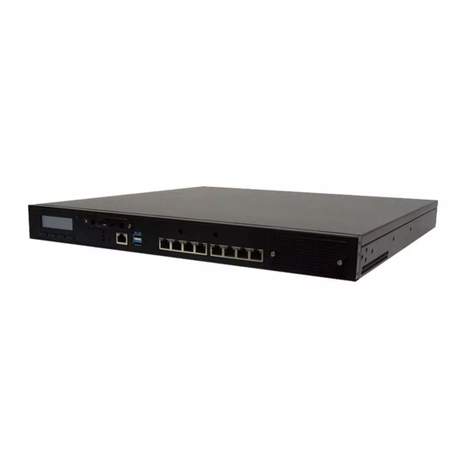
Memotec NetPerformer SDM-9220 Series Manual

NetPerformer®SDM-9220/SDM-9230
Hardware Installation Guide

COPYRIGHTS AND DISCLAIMERS
Published Date: April 2009
This publication contains information proprietary and confidential to Memotec Inc. Any reproduction,
disclosure or unauthorized use of this publication is expressly prohibited except as Memotec Inc. may
otherwise authorize in writing.
Memotec Inc. reserves the right to make changes without notice in product or component design as warranted
by evolution in user needs or progress in engineering or manufacturing technology. Changes which affect the
operation of the unit will be documented in the next revision of the manual.
We have made every effort to ensure the accuracy of the information presented in our documentation.
However, Memotec assumes no responsibility for the accuracy of the information published. Product
documentation is subject to change without notice. Changes, if any, will be incorporated in new editions of
these documents. Memotec may make improvements or changes in the products or programs described within
the documents at any time without notice. Mention of products or services not manufactured or sold by
Memotec is for informational purposes only and constitutes neither an endorsement nor a recommendation for
such products or services.
Memotec Inc. is a wholly owned subsidiary of Comtech EF Data Corp., and its parent company Comtech
Telecommunications Corp (NASDAQ: CMTL).
CXTool, CX-U Series, CX-UA Series, AbisXpress, NetPerformer, AccessGate, ACTView, SDM-8400, and the
SDM-9000 series of products are either registered trademarks or trademarks of Memotec Inc.in Canada, the
United States of America, and in other countries.
Windows is a registered trademark of Microsoft Corporation in the United States and other countries.
Any other trademarks are the property of their respective companies.
Copyright © 2009 Memotec Inc.
Memotec Inc.
7755 Henri Bourassa Blvd. West
Montreal, Quebec
Canada H4S 1P7
Tel.: (514) 738-4781
FAX: (514) 738-4436
www.memotec.com

Memotec Inc.
Contents
Chapter 1: Preface. . . . . . . . . . . . . . . . . . . . . . . . . . . . . . . . . . . . . . . . . . . . . . . . . . . . . . . . . 1-1
1. 1 Product Overview . . . . . . . . . . . . . . . . . . . . . . . . . . . . . . . . . . . . . . . . . . . 1-2
1.1.1 SDM-9220 . . . . . . . . . . . . . . . . . . . . . . . . . . . . . . . . . . . . . . . . . 1-2
1.1.2 SDM-9230 . . . . . . . . . . . . . . . . . . . . . . . . . . . . . . . . . . . . . . . . . 1-2
1.1.3 Sales Contacts . . . . . . . . . . . . . . . . . . . . . . . . . . . . . . . . . . . . . . 1-3
1. 2 About this Document . . . . . . . . . . . . . . . . . . . . . . . . . . . . . . . . . . . . . . . . . 1-4
1.2.1 Naming Conventions . . . . . . . . . . . . . . . . . . . . . . . . . . . . . . . . . 1-4
1.2.2 Audience . . . . . . . . . . . . . . . . . . . . . . . . . . . . . . . . . . . . . . . . . . 1-5
1.2.3 Instructions to the Reader . . . . . . . . . . . . . . . . . . . . . . . . . . . . . 1-5
1.2.4 NetPerformer Document Set . . . . . . . . . . . . . . . . . . . . . . . . . . . 1-5
1.2.5 ACTView 3000 Document Set . . . . . . . . . . . . . . . . . . . . . . . . . . 1-6
1.2.6 Related Documents . . . . . . . . . . . . . . . . . . . . . . . . . . . . . . . . . . 1-6
1. 3 Changes to Console Operations . . . . . . . . . . . . . . . . . . . . . . . . . . . . . . . . 1-7
1. 4 Technical Support . . . . . . . . . . . . . . . . . . . . . . . . . . . . . . . . . . . . . . . . . . . 1-8
1.4.1 Providing Product Numbers to Technical Support . . . . . . . . . . . 1-8
1.4.2 Product Serial Number. . . . . . . . . . . . . . . . . . . . . . . . . . . . . . . . 1-8
1.4.3 Product Work Order Number . . . . . . . . . . . . . . . . . . . . . . . . . . . 1-9
1.4.4 Checking the Contents of Your Product Package . . . . . . . . . . 1-10
1.4.5 Returning a NetPerformer Unit. . . . . . . . . . . . . . . . . . . . . . . . . 1-10
1. 5 Training and Documentation . . . . . . . . . . . . . . . . . . . . . . . . . . . . . . . . . . 1-10
1.5.1 Request for Comments . . . . . . . . . . . . . . . . . . . . . . . . . . . . . . 1-10
1. 6 Notice Concerning HyperTerminal Connections . . . . . . . . . . . . . . . . . . . 1-11
Chapter 2: Compliance Information. . . . . . . . . . . . . . . . . . . . . . . . . . . . . . . . . . . . . . . . . . . 2-1
2. 1 Regulatory – Compliance and Agency Approval . . . . . . . . . . . . . . . . . . . . 2-2
2. 2 Compliance and Regulatory Statements . . . . . . . . . . . . . . . . . . . . . . . . . . 2-3
2.2.1 EU Directive 1999/5 . . . . . . . . . . . . . . . . . . . . . . . . . . . . . . . . . . 2-3
2.2.2 Marking . . . . . . . . . . . . . . . . . . . . . . . . . . . . . . . . . . . . . . . . . . . 2-5
2.2.3 Intent of Use and Network Compatibility . . . . . . . . . . . . . . . . . . 2-6
2.2.4 EN55022 and CISPR22 Statement . . . . . . . . . . . . . . . . . . . . . . 2-7
2.2.5 FCC Part 15 Statement . . . . . . . . . . . . . . . . . . . . . . . . . . . . . . . 2-8
2.2.6 FCC Part 68 Statement . . . . . . . . . . . . . . . . . . . . . . . . . . . . . . . 2-8
2.2.7 Connection to the Telephone Line . . . . . . . . . . . . . . . . . . . . . . . 2-8
2.2.8 Problems, Repair and Warranty. . . . . . . . . . . . . . . . . . . . . . . . 2-10
2.2.9 Industry Canada Statements . . . . . . . . . . . . . . . . . . . . . . . . . . 2-11

Memotec Inc.
2.2.10 The Ringer Equivalence Number (REN) . . . . . . . . . . . . . . . . . 2-11
2.2.11 Notice d'Industrie Canada . . . . . . . . . . . . . . . . . . . . . . . . . . . . 2-11
2.2.12 Indice d’équivalence de la sonnerie (IES) . . . . . . . . . . . . . . . . 2-12
2.2.13 Notice for Users in Australia – Emergency Dialing Warning . . 2-12
2. 3 Environmental Information . . . . . . . . . . . . . . . . . . . . . . . . . . . . . . . . . . . 2-13
2.3.1 Waste Electrical and Electronic Equipment – WEEE . . . . . . . 2-13
2.3.2 Restriction of Hazardous Substances - RoHS. . . . . . . . . . . . . 2-14
2.3.3 Compliance to China RoHS. . . . . . . . . . . . . . . . . . . . . . . . . . . 2-15
2. 4 Safety Warnings and Precautions . . . . . . . . . . . . . . . . . . . . . . . . . . . . . . 2-16
2. 5 Making Changes or Modifications . . . . . . . . . . . . . . . . . . . . . . . . . . . . . . 2-16
Chapter 3: Unpacking. . . . . . . . . . . . . . . . . . . . . . . . . . . . . . . . . . . . . . . . . . . . . . . . . . . . . . 3-1
3. 1 About Unpacking the Unit . . . . . . . . . . . . . . . . . . . . . . . . . . . . . . . . . . . . . 3-2
3.1.1 Selecting a Location . . . . . . . . . . . . . . . . . . . . . . . . . . . . . . . . . 3-2
3.1.2 Size Requirements . . . . . . . . . . . . . . . . . . . . . . . . . . . . . . . . . . 3-2
3.1.3 Distance Requirements . . . . . . . . . . . . . . . . . . . . . . . . . . . . . . . 3-3
3.1.4 Environmental Requirements . . . . . . . . . . . . . . . . . . . . . . . . . . 3-4
3. 2 Preparing the Site . . . . . . . . . . . . . . . . . . . . . . . . . . . . . . . . . . . . . . . . . . . 3-5
3.2.1 What You Will Need. . . . . . . . . . . . . . . . . . . . . . . . . . . . . . . . . . 3-5
Chapter 4: Hardware Installation. . . . . . . . . . . . . . . . . . . . . . . . . . . . . . . . . . . . . . . . . . . . . 4-1
4. 1 Chapter Overview . . . . . . . . . . . . . . . . . . . . . . . . . . . . . . . . . . . . . . . . . . . 4-2
4. 2 Opening the Chassis Casing. . . . . . . . . . . . . . . . . . . . . . . . . . . . . . . . . . . 4-3
4. 3 Installing or Upgrading the DSP Module . . . . . . . . . . . . . . . . . . . . . . . . . . 4-5
4.3.1 Removing a DSP Module . . . . . . . . . . . . . . . . . . . . . . . . . . . . . 4-7
4. 4 Closing the Chassis Casing . . . . . . . . . . . . . . . . . . . . . . . . . . . . . . . . . . . 4-8
4. 5 Removing an Interface Card . . . . . . . . . . . . . . . . . . . . . . . . . . . . . . . . . . . 4-9
4. 6 Hardware Strapping . . . . . . . . . . . . . . . . . . . . . . . . . . . . . . . . . . . . . . . . 4-10
4.6.1 NT/TE Mode . . . . . . . . . . . . . . . . . . . . . . . . . . . . . . . . . . . . . . 4-10
4.6.2 Setting the NT/TE Mode . . . . . . . . . . . . . . . . . . . . . . . . . . . . . 4-11
4.6.3 E1-75 Jumpers . . . . . . . . . . . . . . . . . . . . . . . . . . . . . . . . . . . . 4-12
4. 7 Installing an Interface Card . . . . . . . . . . . . . . . . . . . . . . . . . . . . . . . . . . . 4-16
4. 8 Installing the Unit in a Rack. . . . . . . . . . . . . . . . . . . . . . . . . . . . . . . . . . . 4-19
4. 9 E&M Wiring and Grounding. . . . . . . . . . . . . . . . . . . . . . . . . . . . . . . . . . . 4-21
4.9.1 E&M Grounding Considerations . . . . . . . . . . . . . . . . . . . . . . . 4-23
4. 10 Installing the Ferrites (EMI Filters) . . . . . . . . . . . . . . . . . . . . . . . . . . . . . 4-24

Memotec Inc.
4. 11 Powering the Unit . . . . . . . . . . . . . . . . . . . . . . . . . . . . . . . . . . . . . . . . . . 4-26
4.11.1 SDM-9220 UAC or SDM-9230 UAC Unit Power Cords . . . . . . 4-26
4.11.2 System Status on Power-up. . . . . . . . . . . . . . . . . . . . . . . . . . . 4-28
4. 12 Connecting the Console Terminal . . . . . . . . . . . . . . . . . . . . . . . . . . . . . . 4-30
4.12.1 Important Console and Modem Settings for Startup . . . . . . . . 4-30
4.12.2 Activating the Console Connection . . . . . . . . . . . . . . . . . . . . . 4-31
4. 13 Installing the Licensed Software Options. . . . . . . . . . . . . . . . . . . . . . . . . 4-32
4.13.1 Software License Key . . . . . . . . . . . . . . . . . . . . . . . . . . . . . . . 4-32
4. 14 Connecting the LAN Hub . . . . . . . . . . . . . . . . . . . . . . . . . . . . . . . . . . . . . 4-33
Chapter 5: Product Description . . . . . . . . . . . . . . . . . . . . . . . . . . . . . . . . . . . . . . . . . . . . . . 5-1
5. 1 SDM-9220/9230 Base Unit . . . . . . . . . . . . . . . . . . . . . . . . . . . . . . . . . . . . 5-2
5. 2 Optional Hardware. . . . . . . . . . . . . . . . . . . . . . . . . . . . . . . . . . . . . . . . . . . 5-3
5. 3 Base Unit Chassis . . . . . . . . . . . . . . . . . . . . . . . . . . . . . . . . . . . . . . . . . . . 5-4
5.3.1 Physical Dimensions . . . . . . . . . . . . . . . . . . . . . . . . . . . . . . . . . 5-4
5.3.2 System Status LEDs . . . . . . . . . . . . . . . . . . . . . . . . . . . . . . . . . 5-4
5. 4 Ethernet Ports . . . . . . . . . . . . . . . . . . . . . . . . . . . . . . . . . . . . . . . . . . . . . . 5-6
5.4.1 Ports. . . . . . . . . . . . . . . . . . . . . . . . . . . . . . . . . . . . . . . . . . . . . . 5-6
5.4.2 LAN Status LEDs . . . . . . . . . . . . . . . . . . . . . . . . . . . . . . . . . . . . 5-6
5.4.3 LAN Cables . . . . . . . . . . . . . . . . . . . . . . . . . . . . . . . . . . . . . . . . 5-7
5. 5 Console Port . . . . . . . . . . . . . . . . . . . . . . . . . . . . . . . . . . . . . . . . . . . . . . . 5-8
5.5.1 Port. . . . . . . . . . . . . . . . . . . . . . . . . . . . . . . . . . . . . . . . . . . . . . . 5-8
5.5.2 Console Cable . . . . . . . . . . . . . . . . . . . . . . . . . . . . . . . . . . . . . . 5-8
5. 6 Power Supply. . . . . . . . . . . . . . . . . . . . . . . . . . . . . . . . . . . . . . . . . . . . . . . 5-9
5.6.1 SDM-9220 UAC and SDM-9230 UAC . . . . . . . . . . . . . . . . . . . . 5-9
5.6.2 SDM-9220 DC and SDM-9230 DC . . . . . . . . . . . . . . . . . . . . . . 5-9
5. 7 Rackmount Kit . . . . . . . . . . . . . . . . . . . . . . . . . . . . . . . . . . . . . . . . . . . . . 5-10
5. 8 DSP Modules. . . . . . . . . . . . . . . . . . . . . . . . . . . . . . . . . . . . . . . . . . . . . . 5-11
5.8.1 DSP-160 Module . . . . . . . . . . . . . . . . . . . . . . . . . . . . . . . . . . . 5-11
5.8.2 High-density DSP Module . . . . . . . . . . . . . . . . . . . . . . . . . . . . 5-12
5. 9 Interface Cards . . . . . . . . . . . . . . . . . . . . . . . . . . . . . . . . . . . . . . . . . . . . 5-13
5.9.1 Analog Voice Interfaces . . . . . . . . . . . . . . . . . . . . . . . . . . . . . . 5-13
5.9.2 Channelized Digital Interfaces . . . . . . . . . . . . . . . . . . . . . . . . . 5-17
5.9.3 Dual Serial Port (WAN) Interface . . . . . . . . . . . . . . . . . . . . . . . 5-22
5.9.4 Interface Card Status LEDs . . . . . . . . . . . . . . . . . . . . . . . . . . . 5-23
5.9.5 FXS and FXO Interface Cards . . . . . . . . . . . . . . . . . . . . . . . . . 5-26

Memotec Inc.
5.9.6 E&M Interface Card . . . . . . . . . . . . . . . . . . . . . . . . . . . . . . . . . 5-27
5.9.7 T1/E1 and ISDN-BRI S/T Interface Cards . . . . . . . . . . . . . . . . 5-29
5.9.8 Supporting E1-75 on a T1/E1 Port. . . . . . . . . . . . . . . . . . . . . . 5-30
Chapter 6: Serial Port and User Equipment Connections. . . . . . . . . . . . . . . . . . . . . . . . . 6-1
6. 1 Serial Port . . . . . . . . . . . . . . . . . . . . . . . . . . . . . . . . . . . . . . . . . . . . . . . . . 6-2
6. 2 Custom HD-26 Cables . . . . . . . . . . . . . . . . . . . . . . . . . . . . . . . . . . . . . . . 6-2
6. 3 Connecting the User Equipment . . . . . . . . . . . . . . . . . . . . . . . . . . . . . . . . 6-4
6.3.1 Activating the User Equipment Connection . . . . . . . . . . . . . . . . 6-4
6. 4 WAN/User Port Specifications. . . . . . . . . . . . . . . . . . . . . . . . . . . . . . . . . . 6-5
6. 5 Custom Serial Cable Specifications . . . . . . . . . . . . . . . . . . . . . . . . . . . . . 6-6
6.5.1 V.35/V.11 Cables. . . . . . . . . . . . . . . . . . . . . . . . . . . . . . . . . . . . 6-6
6.5.2 TIA-232 (V.24) Cables . . . . . . . . . . . . . . . . . . . . . . . . . . . . . . . . 6-6
6.5.3 X.21 Cables . . . . . . . . . . . . . . . . . . . . . . . . . . . . . . . . . . . . . . . . 6-6
6.5.4 X.21 EU Cables . . . . . . . . . . . . . . . . . . . . . . . . . . . . . . . . . . . . . 6-7
6.5.5 TIA-449 (V.36) Cables . . . . . . . . . . . . . . . . . . . . . . . . . . . . . . . . 6-7
6.5.6 TIA-530 Cables . . . . . . . . . . . . . . . . . . . . . . . . . . . . . . . . . . . . . 6-7
6. 6 Serial Port Connector and Custom HD-26 Cable Set Connectivity. . . . . . 6-8
Chapter 7: Networking Features . . . . . . . . . . . . . . . . . . . . . . . . . . . . . . . . . . . . . . . . . . . . . 7-1
7. 1 GSM A-bis/A-ter Optimization . . . . . . . . . . . . . . . . . . . . . . . . . . . . . . . . . . 7-2
7. 2 Voice Channels . . . . . . . . . . . . . . . . . . . . . . . . . . . . . . . . . . . . . . . . . . . . . 7-3
7. 3 Network Connections . . . . . . . . . . . . . . . . . . . . . . . . . . . . . . . . . . . . . . . . 7-4
7. 4 Network Management and Security . . . . . . . . . . . . . . . . . . . . . . . . . . . . . 7-4
Chapter 8: Troubleshooting Tips. . . . . . . . . . . . . . . . . . . . . . . . . . . . . . . . . . . . . . . . . . . . . 8-1
8. 1 Symptoms, Problems, and Solutions . . . . . . . . . . . . . . . . . . . . . . . . . . . . 8-2
Chapter 9: E&M-PTT Interface Card . . . . . . . . . . . . . . . . . . . . . . . . . . . . . . . . . . . . . . . . . . 9-1
9. 1 About the E&M-PTT Interface Card . . . . . . . . . . . . . . . . . . . . . . . . . . . . . 9-2
9. 2 Hardware Features . . . . . . . . . . . . . . . . . . . . . . . . . . . . . . . . . . . . . . . . . . 9-2
9.2.1 Specifications. . . . . . . . . . . . . . . . . . . . . . . . . . . . . . . . . . . . . . . 9-3
9.2.2 Cable and Connector. . . . . . . . . . . . . . . . . . . . . . . . . . . . . . . . . 9-4
9. 3 About Push To Talk (PTT). . . . . . . . . . . . . . . . . . . . . . . . . . . . . . . . . . . . . 9-6
9.3.1 Fixed Control Station Scenario . . . . . . . . . . . . . . . . . . . . . . . . . 9-6
9.3.2 Two Remote Locations Scenario. . . . . . . . . . . . . . . . . . . . . . . . 9-8
9. 4 Configuring Push To Talk . . . . . . . . . . . . . . . . . . . . . . . . . . . . . . . . . . . . . 9-9

Memotec Inc.
9.4.1 Configuring the E&M-PTT Physical Port (LINK). . . . . . . . . . . . . 9-9
9.4.2 Configuring the E&M-PTT Channels (CHANNEL) . . . . . . . . . . 9-10
Index . . . . . . . . . . . . . . . . . . . . . . . . . . . . . . . . . . . . . . . . . . . . . . . . . . . . . . . . . . . . . . .Index-1

Memotec Inc.

Memotec Inc.
List of Figures
Location of Product Numbering on the Nameplate . . . . . . . . . . . . . . . . . . . . . . . .1-9
Front View of the SDM-9220/9230 . . . . . . . . . . . . . . . . . . . . . . . . . . . . . . . . . . .3-2
Removing the Cover from the Unit Chassis . . . . . . . . . . . . . . . . . . . . . . . . . . . . .4-4
Location of Optional Hardware on the Main Board . . . . . . . . . . . . . . . . . . . . . . . .4-5
Replacing the Cover onto the Unit Chassis . . . . . . . . . . . . . . . . . . . . . . . . . . . . .4-8
JP5 AND JP6 locations . . . . . . . . . . . . . . . . . . . . . . . . . . . . . . . . . . . . . . . . . .4-11
Position of Jumper Connectors J4 and J7 on the Dual Port T1/E1 Interface Card . .4-13
Location of Interface Cards in the SDM-9220/9230 Slots . . . . . . . . . . . . . . . . . .4-17
Rackmount Brackets . . . . . . . . . . . . . . . . . . . . . . . . . . . . . . . . . . . . . . . . . . . .4-19
Completed Rackmount Installation . . . . . . . . . . . . . . . . . . . . . . . . . . . . . . . . . .4-20
Four-wire E&M Connections . . . . . . . . . . . . . . . . . . . . . . . . . . . . . . . . . . . . . . .4-22
Two-wire E&M Connections . . . . . . . . . . . . . . . . . . . . . . . . . . . . . . . . . . . . . . .4-22
Installing a ferrite with an RJ-45/RJ-48 connector . . . . . . . . . . . . . . . . . . . . . . .4-25
Power Cords for SDM-9220 UAC or SDM-9230 UAC Unit . . . . . . . . . . . . . . . . . . .4-26
Harness and Wire for SDM-9220 DC or SDM-9230 DC Power Connection . . . . . . .4-27
Rear View of the SDM-9230 UAC . . . . . . . . . . . . . . . . . . . . . . . . . . . . . . . . . . . .5-2
SDM-9220/9230 Installed with rackmount brackets . . . . . . . . . . . . . . . . . . . . . .5-10
DSP-160 module . . . . . . . . . . . . . . . . . . . . . . . . . . . . . . . . . . . . . . . . . . . . . .5-11
High-density DSP module . . . . . . . . . . . . . . . . . . . . . . . . . . . . . . . . . . . . . . . .5-12
The Dual FXS interface card (top) . . . . . . . . . . . . . . . . . . . . . . . . . . . . . . . . . .5-14
The Quad FXS interface card (bottom) . . . . . . . . . . . . . . . . . . . . . . . . . . . . . . .5-14
The Dual FXO interface card (top) . . . . . . . . . . . . . . . . . . . . . . . . . . . . . . . . . .5-15
The Quad FXO interface card (bottom) . . . . . . . . . . . . . . . . . . . . . . . . . . . . . . .5-15
The E&M interface card . . . . . . . . . . . . . . . . . . . . . . . . . . . . . . . . . . . . . . . . . .5-16
The Single Port T1/E1 interface card (top) . . . . . . . . . . . . . . . . . . . . . . . . . . . .5-19
The Dual Port T1/E1 interface card (bottom) . . . . . . . . . . . . . . . . . . . . . . . . . . .5-19
The ISDN-BRI S/T interface card . . . . . . . . . . . . . . . . . . . . . . . . . . . . . . . . . . .5-21
The Dual Serial port interface card . . . . . . . . . . . . . . . . . . . . . . . . . . . . . . . . . .5-23
RJ-11 pinout (female jack) . . . . . . . . . . . . . . . . . . . . . . . . . . . . . . . . . . . . . . .5-26

Memotec Inc.
RJ-45 pinout (female jack) for E&M interface card . . . . . . . . . . . . . . . . . . . . . . 5-28
RJ-48 to E1-75 dual bnc adaptor cable . . . . . . . . . . . . . . . . . . . . . . . . . . . . . . 5-31
Balun Adaptor with Patch Cable . . . . . . . . . . . . . . . . . . . . . . . . . . . . . . . . . . . 5-32
The E&M-PTT Interface Card . . . . . . . . . . . . . . . . . . . . . . . . . . . . . . . . . . . . . . 9-3
RJ-45 Pinout (female jack) for E&M-PTT Interface Card . . . . . . . . . . . . . . . . . . . . 9-5
SETUP Command Paths in the CLI Tree for Push To Talk Support . . . . . . . . . . . . . 9-9

Memotec Inc.
List of Tables
Compatible Telecom Services. . . . . . . . . . . . . . . . . . . . . . . . . . . . . . . . . . . . . . . . . . . . . . . . . . . . . 2-6
Jumper installation parameters . . . . . . . . . . . . . . . . . . . . . . . . . . . . . . . . . . . . . . . . . . . . . . . . . . . 4-14
E&M wiring . . . . . . . . . . . . . . . . . . . . . . . . . . . . . . . . . . . . . . . . . . . . . . . . . . . . . . . . . . . . . . . . . . 4-21
SDM-9220/9230 ports requiring a ferrite . . . . . . . . . . . . . . . . . . . . . . . . . . . . . . . . . . . . . . . . . . . . 4-24
Front Panel LED States During System Startup . . . . . . . . . . . . . . . . . . . . . . . . . . . . . . . . . . . . . . 4-28
Basic features of the SDM-9220/9230 unit . . . . . . . . . . . . . . . . . . . . . . . . . . . . . . . . . . . . . . . . . . . 5-2
Optional Hardware. . . . . . . . . . . . . . . . . . . . . . . . . . . . . . . . . . . . . . . . . . . . . . . . . . . . . . . . . . . . . . 5-3
List of physical ports and their port numbers. . . . . . . . . . . . . . . . . . . . . . . . . . . . . . . . . . . . . . . . . . 5-3
STATUS LED states . . . . . . . . . . . . . . . . . . . . . . . . . . . . . . . . . . . . . . . . . . . . . . . . . . . . . . . . . . . . 5-4
ALARM LED states . . . . . . . . . . . . . . . . . . . . . . . . . . . . . . . . . . . . . . . . . . . . . . . . . . . . . . . . . . . . . 5-5
RJ-45 pinout for Ethernet LAN port . . . . . . . . . . . . . . . . . . . . . . . . . . . . . . . . . . . . . . . . . . . . . . . . . 5-7
Status LED indicators on analog voice interface cards . . . . . . . . . . . . . . . . . . . . . . . . . . . . . . . . . 5-23
Status LED indicators on channelized digital interface cards . . . . . . . . . . . . . . . . . . . . . . . . . . . . 5-25
RJ-45 pinout for E&M interface card . . . . . . . . . . . . . . . . . . . . . . . . . . . . . . . . . . . . . . . . . . . . . . . 5-27
RJ-48 pinout for single/dual port T1/E1 interface cards . . . . . . . . . . . . . . . . . . . . . . . . . . . . . . . . 5-29
RJ-48 pinout for ISDN-BRI S/T interface card. . . . . . . . . . . . . . . . . . . . . . . . . . . . . . . . . . . . . . . . 5-29
Serial connector and NetPerformer custom HD-26 cable set . . . . . . . . . . . . . . . . . . . . . . . . . . . . . 6-8
Packetization of DSP packets . . . . . . . . . . . . . . . . . . . . . . . . . . . . . . . . . . . . . . . . . . . . . . . . . . . . . 7-3
RJ-45 pinout for E&M-PTT interface card . . . . . . . . . . . . . . . . . . . . . . . . . . . . . . . . . . . . . . . . . . . . 9-4
Push-To-Talk Application: Scenario 1 . . . . . . . . . . . . . . . . . . . . . . . . . . . . . . . . . . . . . . . . . . . . . . . 9-7
Push-To-Talk Application: Scenario 2 . . . . . . . . . . . . . . . . . . . . . . . . . . . . . . . . . . . . . . . . . . . . . . . 9-8

Memotec Inc.

1
Memotec Inc. 1-1
Preface

SDM-9220/9230 Hardware Installation Guide
1-2 Memotec Inc.
1.1 Product Overview
1.1.1 SDM-9220
The NetPerformer SDM-9220 is an entry-level standalone chassis designed for network
convergence at the branch office level. It is a high speed, low cost, flexible and powerful
unit that supports 8 analog or BRI/ST digital voice connections in a multitude of
application scenarios.
The SDM-9220 base unit has:
• One serial port equipped with HD-26 female connector
• Two 10/100Base-T Ethernet ports (RJ45 connectors)
• One console port
• Two expansion slots
• All UAC base units come equipped with universal AC power supply and a choice
of 120 VAC North American or 240 VAC European power cord (must be speci-
fied at time of ordering)
• The –48VDC versions include a 6-foot wiring harness
• A DB9F-DB9F console cable and 19-inch rackmount kit are also included in the
product package
• A custom cable (HD-26 male connector) is required for the serial port, available
from Memotec Inc. or your NetPerformer distributor.
The basic software set provides support of PowerCell Voice and Data (including legacy
user data) and IP routing over Ethernet, serial or digital ports using PPP or Frame Relay
RFC-1490. Optional software licenses can be procured for support of GSM, SkyPerformer
satellite access and TCP Acceleration.
1.1.2 SDM-9230
The NetPerformer SDM-9230 is a standalone chassis designed for network convergence at
the branch office level. It is a high speed, low cost, flexible and powerful unit that supports
analog/digital voice and data in a multitude of application scenarios. It is ideal for branch
offices that require support for up to 12 analog or 120 digital telephony channels.
The SDM-9230 base unit has:
• One serial port equipped with HD-26 female connector
• Two 10/100Base-T Ethernet ports (RJ45 connectors)
• One console port
• Three expansion slots for analog voice, digital (T1/E1) voice/data, BRI/ST voice/
data and dual serial interface cards

Preface
Memotec Inc. 1-3
• All UAC base units come equipped with universal AC power supply and a choice
of 120 VAC North American or 240 VAC European power cord (must be speci-
fied at time of ordering)
• The –48VDC versions include a 6-foot wiring harness
• A DB9F-DB9F console cable and 19-inch rackmount kit are also included in the
product package
• A custom cable (HD-26 male connector) is required for the serial port, available
from Memotec Inc. or your NetPerformer distributor.
The basic software set provides support of PowerCell Voice and Data (including legacy
user data) and IP routing over Ethernet, serial or digital ports using PPP or Frame Relay
RFC-1490. Optional software licenses can be procured for support of GSM, SkyPerformer
satellite access, TCP Acceleration and ATM.
1.1.3 Sales Contacts
To order NetPerformer units, DSP modules, cables and optional parts, contact Memotec
Inc. or your NetPerformer distributor. To contact Memotec Inc.:
• Mail:
Memotec Inc.
7755 Henri Bourassa Blvd. West
Montreal, Quebec
Canada H4S 1P7
• Telephone: +1 (514) 738-4781 (regular business hours, EST)
Fax: + (1) 514 738 4436
•Web:http://www.memotec.com

SDM-9220/9230 Hardware Installation Guide
1-4 Memotec Inc.
1.2 About this Document
This document, NetPerformer® SDM-9220/9230 Hardware Installation Guide, provides
the following information about the SDM-9220 and SDM-9230:
• Regulatory compliance information (“Compliance Information” on page 2-1)
• Unpacking instructions (“Unpacking” on page 3-1)
• Product description (“Product Description” on page 5-1)
• Hardware installation instructions (“Hardware Installation” on page 4-1)
• Troubleshooting procedures (“Troubleshooting Tips” on page 8-1)
• Serial port specifications and user equipment connection (“Serial Port and User
Equipment Connections” on page 6-1)
• Networking features (“Networking Features” on page 7-1)
• Notice concerning HyperTerminal connection (“Notice Concerning HyperTermi-
nal Connections” on page 1-11).
For information on configuring the NetPerformer, consult the NetPerformer System
Reference. See the “NetPerformer Document Set” on page 1-5 for a list of other
references.
NOTE: All NetPerformer documents are available on the NetPerformer Compan-
ion CD, which is included with your product package.
Caution: All documents on the NetPerformer Companion CD, including this guide,
must be opened with Adobe™ Acrobat Reader, which is provided on the CD.
If you open a NetPerformer document with an earlier version of Acrobat Reader,
some of the text will not appear in its intended format. This can make the text
difficult or impossible to read correctly, especially from a printed copy.
1.2.1 Naming Conventions
In this document:
• The notation SDM-9220/9230 denotes the SDM-9220 and SDM-9230 prod-
ucts.
The product is identified on the front of the unit.
• SDM-9220 products include the SDM-9220 UAC model and the SDM-9220 DC
model.
• SDM-9230 products include the SDM-9230 UAC model and the SDM-9230 DC
model.
The model number is identified on the nameplate on the bottom of the unit.

Preface
Memotec Inc. 1-5
1.2.2 Audience
This document is intended for use by NetPerformer system administrators as well as
technicians who are qualified to set up, configure and troubleshoot a NetPerformer
Enterprise Network.
Installation of NetPerformer hardware requires knowledge and proficiency in the
configuration, operation, maintenance and security of all enterprise network elements in
your application. You should also have a thorough understanding of telecommunications
and be familiar with the networking strategies and telephony solutions currently used by
your organization.
1.2.3 Instructions to the Reader
Instructions to the reader include notes, cautions and warnings, which are distinguished
from the rest of the text by distinctive formatting and icons. Here is an example of each:
NOTE: A note may contain a reference, tip or other information related to the subject
at hand. The content of a note is intended to be helpful or of interest to the
reader.
Caution: A caution contains an instruction that the reader must follow in order to
prevent damage to equipment, network failure or loss of data.
The content of a caution must be read carefully and explicitly obeyed
Warning: A warning contains an instruction that the reader must follow in order to
prevent electrical shock, death or serious injury to personnel.
The content of a warning must be read carefully and explicitly obeyed.
1.2.4 NetPerformer Document Set
For complete information on the NetPerformer, consult the following:
• NetPerformer System Reference
Includes detailed information on new generation NetPerformer features, menus,
commands, parameters and statistics displays for versions V10.2.1 R02 and
higher. This System Reference, which is divided into fascicles for each applica-
tion, also integrates all information from the Addenda to the NetPerformer Sys-
tem Reference Manualfor versions 9.0.0, 9.1.0, 9.2.0 and 10.1.X.
• NetPerformer Hardware Installation Guides
These documents describe the hardware specific to each NetPerformer product,
including installable options, complete installation instructions and firmware
download procedures.
• NetPerformer Release Bulletins

SDM-9220/9230 Hardware Installation Guide
1-6 Memotec Inc.
These documents summarize the system specifications, software fixes and
changes, and post-production documentation changes for a particular NetPer-
former release.
• NetPerformer Network Design Guide
Offers valuable tips on how to design a NetPerformer application for maximum
efficiency, including an analysis of data and voice traffic throughput issues and
the impact of traffic flow. Provides examples of network setup and traffic meas-
urement using various NetPerformer products.
1.2.5 ACTView 3000 Document Set
If you are managing your NetPerformer network with ACTView 3000 you can refer to the
following:
• ACTView 3000 Quick Start Guide for Windows
Use this guide to install ACTView 3000 in a Windows 2000 or XP environment
with HP OpenView Network Node Manager (NNM) 7.5.
• ACTView 3000 Quick Start Guide for Sun Solaris
Use this guide to install ACTView 3000 in a Sun Solaris environment (version
2.7 or later versions) with HP OpenView Network Node Manager (NNM)
B06.20 or later versions.
• ACTView 3000 User Guide
This document describes the features and functions of ACTView 3000. It may be
used for all operating systems (Sun Solaris, Windows 2000/XP).
• ACTView 3000 Element Manager User Guide
Describes the features and functions of all ACTView 3000 element managers for
all operating systems (Sun Solaris, Windows 2000/XP).
• ACTView 3000 Release Bulletins
These documents summarize the system specifications, software fixes and
changes, and post-production documentation changes for a particular ACTView
3000 release.
1.2.6 Related Documents
All of the documents listed here are available on the NetPerformer Companion CD,
which is included with your product package (Part no. 520-0081-001; Ordering part no.
161-0692-001).

Preface
Memotec Inc. 1-7
1.3 Changes to Console Operations
The following change to console operations was made in NetPerformer firmware version
V9.2.0, and still applies to firmware version V10.1.X and higher. If you are familiar with
earlier versions of the NetPerformer firmware, this change should be taken into
consideration before you configure or manage the product.
• The way you access the NetPerformer console has changed to allow for multiple
user profiles:
Caution: The default LOGIN is now ADMIN instead of ACT.
NOTE: The default PASSWORD for this login remains SETUP.
For full instructions on setting up user profiles, refer to the Quick Configuration module
of the NetPerformer System Reference.

SDM-9220/9230 Hardware Installation Guide
1-8 Memotec Inc.
1.4 Technical Support
NetPerformer Technical Support is designed to meet your full range of support needs.
From basic service to mission-critical support, we are committed to ensuring your success
with NetPerformer products. We tailor different support plans to meet your evolving
business requirements. By employing state-of-the-art products and the latest technologies
available, we provide some of the fastest, most efficient service in the industry.
Our entire support organization is focused on complete customer satisfaction and
providing immediate solutions to your business needs.
You can contact NetPerformer Technical Support by calling or sending email to our
helpdesk facilities:
Telephone: +1 (514) 738-4781 during regular business hours, EST (GMT-05:00)
Email: NetPerformer[email protected]
Be prepared to provide the following information:
• Your name
• Company name
• Your location
• Telephone number
• Product serial number (see next section)
• Product work order number (see next section)
• Detailed problem description
• Remote access to the troubled unit via Telnet or dial-up modem.
1.4.1 Providing Product Numbers to Technical Support
You may be requested to provide the product serial number and work order number when
communicating with NetPerformer Technical Support.
1.4.2 Product Serial Number
The product serial number is provided in two locations on the SDM-9220/9230 chassis:
• The rear of the unit (see “Rear View of the SDM-9230 UAC” on page 5-2 for
location of label)
• The nameplate on the underside of the unit (see Figure 1-1, below).
Other manuals for NetPerformer SDM-9220 Series
1
This manual suits for next models
1
Table of contents
Other Memotec Network Hardware manuals
Popular Network Hardware manuals by other brands
MikroTik
MikroTik FiberBox Plus quick start guide
Overland Storage
Overland Storage SnapServer XSR 120 Assembly instructions

Techroutes
Techroutes LLDP Configuration
Milestone
Milestone Husky M50 Advanced quick start guide
Omron
Omron DEVICENET SAFETY - 04-2005 Operation manual

Leonton
Leonton CEG5-0602-SFP-Lite Series Hardware user manual
