Memotech Limited MTX 512 User manual

MTX Service Manual

MTX 500/512 SERVICE MANUAL
&
TECHNICAL INF RMATI N
Memotech Limited
Witney
xon X8 6BX
Tel: (0993) 2997
Tlx: UK83372 MEMTEC G
MTX Service Manual

C NTENTS
Page
verall Description...................................1
Internal Expansions compatibility.....................4
Z80 CPU...............................................6
Z80 Pin Description.................................7
Z80 CTC..............................................10
Z80 CTC Pin Description............................11
Z80 DART.............................................13
Z80 DART Pin Description...........................14
TMS 9929 VDP.........................................17
PAL VDP Horizontal Timing..........................18
9929 Signal Waveforms..............................19
MTX Series System Bus................................20
System Block Diagram...............................21
MTX Disassembly Instructions.........................22
Trouble Shooting Guide...............................25
Symptom 1
No Display/Black and white display............26
Symptom 2
Blank screen/no humming/power on..............28
Symptom 3
Corrupt Video Display or characters...........30
Symptom 4
Bad hum bars..................................31
Symptom 5
Green screen and hum..........................32
Symptom 6
Load and save problems........................35
Symptom 7
Sound problems................................37
Symptom 8
Keyboard......................................38
Symptom 9
Memory Exps, R M Exps, RS232, Printer.........40
UM1286 Modulator.....................................42
Testing and Setting up........................43
Mother board Links and PAL Colour coding.............44
PR M Codes for memory expansion boards...............45
MTX Service Manual

Timing Chain.........................................46
Rear Plastic moulding................................48
PARTS LIST...........................................49
MTX500/512....................................50
PAL Video Board...............................54
Keyboard/Keytops..............................56
Power Supply..................................59
Plastic Rear Panel............................60
Packing.......................................60
RS232 Board...................................62
32K Memory Expansion..........................64
R M Expansion.................................65
Schematic Diagrams
MTX 4000-04...................................66
PAL Video Board...............................68
NTSC Video Board..............................69
Memory Expansion Board........................70
RS232 Communications Board....................71
MTX Service Manual

1
INTR DUCTI N
verall Description
The MTX Series personal computer systems are high
performance 8-bit computers uniquely designed to
operate in memory intensive R M-based or DISC-
based environments. The choice of the Z80 A
Microprocessor and the TMS 9929A series video
processor as the key components of the hardware
architecture is consistent with a low cost R M-
based system with colour TV output plus the
capability to expand to accommodate a fully RAM-
based Disc operating system such as CP/M,
utilising a high quality 80 column colour monitor
output.
The memory size can be either 32K or 64K Bytes as
standard, expandable to 512K Bytes. There is a
separate 16K Byte dedicated video memory. A 24K
Byte R M contains MTX - BASIC, the systems
monitor, supplementary languages and utilities.
The standard interfaces included are tape cassette
(Read/Write to 2400 baud), Keyboard, Cartridge
Port, Twin Joysticks, Parallel Centronics type
printer port, uncommitted Parallel Input/ utput
port, colour TV output with sound, composite video
output - monochrome or colour, and audio output.
ptional interfaces include a completely
independent twin RS232C with buffered bus
extension, Colour 80 Column Board, Floppy Disc
System, Silicon disc fast access RAM boards, and a
Winchester Disc System.
The Keyboard consists of 79 full travel typewriter
style keys mounted on a steel base plate which is
fitted to the Aluminium enclosure. Aluminium was
chosen for good heat dissipation, durability and
RFI shielding.
MTX Service Manual

2
CPU Board
Mounted in the lower chassis, the CPU board
accommodates:
Z80A CPU operating at 4Mhz.
24K of R M which contains:
MTX BASIC - incorporating sophisticated MTX L G -type
graphics commands.
MTX N DDY - Interactive screen manipulation routines.
FR NT PANEL DISPLAY - incorporating Z80
Assembler/Disassembler plus Z80 Register, Memory and
Program display and manipulation routines.
VIDE DISPLAY PR CESS R - with 16K dedicated video-RAM.
USER-RAM - 32K on the MTX500 and 64K on the MTX512.
User RAM size is constant under all display formats.
VIDE B ARD - for television and sound signal encoding.
REAL TIME CL CK
CHARACTER SETS - Numeric, upper case, lower case,
user-definable characters and user-definable sprites.
Resident international character sets and appropriate
keyboard layouts for UK, USA, Finland, France, Germany,
Spain,Denmark and Sweden.
Display
Colour TV and/or Video Monitor
40 column x 24 line display as standard, with
optional Colour 80 column board. (FDX or HDX disc
based system required).
Display Facilities:
FULL SCREEN HANDLING
EIGHT USER DEFINABLE VIRTUAL SCREENS
SCREEN F RMATS
Text: 40 x 24 characters
Text with graphics: 32 x 24 text with 256 x 192
pixels in 16 colours
MTX Service Manual

3
Graphics Facilities
Up to 32 independently controllable user definable
sprites, plus pattern plane and backdrop plane.
High level sprite-orientated graphics commands.
Input/ utput
Provided as standard:
1. CASSETTE P RT (variable rate, up to 2 400 baud)
2. UNC MMITTED PARALLEL INPUT/ UTPUT P RT
3. TW J YSTICK P RTS with industry standard pin-
outs
4. F UR CHANNEL S UND UNDER S FTWARE C NTR L -
three independent voices plus pink noise output
through TV speaker, or through separate Hi-Fi
output
5. M NIT R UTPUT - composite video signal (1V
peak to peak) CARTRIDGE P RT
6. PARALLEL PRINTER P RT (compatible with
Centronics-type printers)
Expansions
Up to two expansion boards may be added
internally. These may be Memory (RAM) Boards or
the Communications Board.
MEM RY B ARDS
RAM may be increased by the addition of boards
which provide 32K, 64K, 128K or 256K of memory, up
to a maximum of 512K.
C MMUNICATI NS B ARD
Available as an internal expansion, this board
carries two completely independent RS232
interfaces (running at up to 19 200 baud) with
full handshaking and modem communication lines,
and also the disc drive bus. The Communications
Board is required to run the FDX and HDX disc
based systems and the MTX Node/Ring System.
MTX Service Manual

4
N DE/RING SYSTEM
Communications software and interfacing enabling
construction of MTX Ring Systems. The system is
interrupt driven and runs in conjunction with the
twin RS232 Communications Board.
Compatibility of the memory boards and Communications
Board is given below.
Compatibility table of internal expansion boards
RAM B ARDS
32k 64k 128k 256k Comms Board
32k * * * *
64k * * * * *
128k * * * * *
256k * * * * *
Comms * * * *
Board
R M Expansions
Via the cartridge port or disc drive bus these provide:
MTX PASCAL
N DE SYSTEM software
Business, Education and Games software
Suitable Printers
Centronics-type parallel printers
RS232 serial printers (requires Communications
Board)
Power Supply Unit
Input: 220/240 VAC 50/60 Hz. or 110/115 VAC 50/60
Hz.
utput: 22.5 VAC, 1A tapped at 18V and 9V.
Dimensions in millimetres: Width 92 Depth 110
Height 70 Weight: 1.0 kilogram
The PSU is double insulated and has a side mounted
rocker switch which is internally illuminated when
the unit is on. The mains transformer is located
between two groups of four anti-vibration noise
absorbing rubber mount. Extensive strain relief
MTX Service Manual

5
mouldings are incorporated in the PSU casing to
support the input and output cables. The output
cable terminates in a 240 degree, six pin DIN
connector. The PSU is supplied as a sealed unit.
MTX Service Manual
6
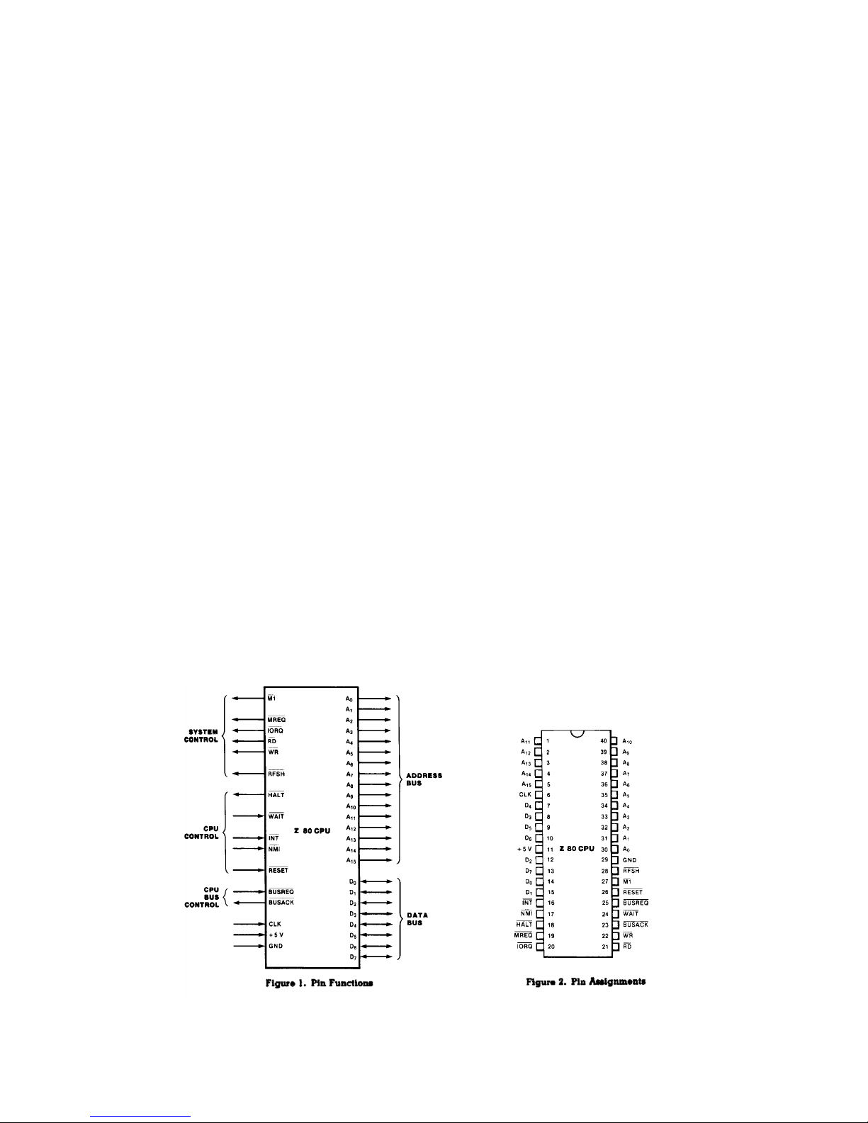
Z80 CPU
The instruction set contains 158 instructions. The 78
instructions of the 8080A are included as a subset;
8080A software compatibility is maintained.
Eight MHz, 6 MHz, 4MHz and 2.5 MHz clocks for the Z80H,
Z80B, Z80A and Z80 CPU result in rapid instruction
execution with consequent high data throughput.
The extensive instruction set includes string, bit,
byte and word operations. Block searches and block
transfers together with indexed and relative addressing
result in the most powerful data handling capabilities
in the microcomputer industry.
The Z80 microprocessors and associated family of
peripheral controllers are linked by a vectored
interrupt system. This system may be daisy-chained to
allow implementation of a priority interrupt scheme.
Little, if any, additional logic is required for daisy-
chaining.
Duplicate sets of both general-purpose and flag
registers are provided, easing the design and operation
of system software through single-context switching,
background-foreground programming and single-level
interrupt processing. In addition, two 16-bit index
registers facilitate program processing of tables and
arrays.
There are three modes of high-Speed interrupt
processing: 8080 similar, non-Z80 peripheral device
and Z80 Family peripheral with or without daisy chain.
n-chip dynamic memory refresh counter.
MTX Service Manual

7
Pin description
A0-A15.
Address Bus (output, active High,·3-state). A0-
A15 form a 16-bit address bus. The Address Bus
provides the address for memory data bus exchanges
(up to 64K bytes) and for I/ device exchanges.
BUSACK.
Bus Acknowledge (output, active Low). Bus
Acknowledge indicates to the requesting device
that the CPU address bus, data bus and control
Signals MREQ, I RQ, RD and WR have entered their
high-impedance states. The external circuitry can
now control these lines.
BUSREQ.
Bus Request (input, active Low). Bus Request has
a higher priority than NMI and is always
recognized at the end of the current machine
cycle. BUSREQ forces the CPU address bus, data
bus, and control signals MREQ, I RQ, RD, and WR to
go to a high-impedance state so that other devices
can control these lines. BUSREQ is normally wire-
Red and requires an external pull up for these
applications. Extended BUSREQ periods due to
extensive DMA operations can prevent the CPU from
properly refreshing dynamic RAMs.
D0-D7.
Data Bus (input/output, active High 3-state). D0-
D7 constitute an 8-bit bidirectional data bus,
used for data exchanges with memory and I/ .
HALT.
Halt State (output, active Low). HALT indicates
that the CPU has executed a Halt instruction and
is awaiting either a non-maskable or a maskable
interrupt (with the mask enabled) before operation
can resume. While halted, the CPU executes N Ps
to maintain memory refresh.
INT.
Interrupt Request (input, active Low). Interrupt
Request is generated by I/ devices. The CPU
honors a request at the end of the current
instruction if the internal software-controlled
interrupt enable flip-flop (IFF) is enabled. INT
is normally wire- Red and requires an external
pull up for these applications.
MTX Service Manual

8
I RQ.
Input/ utput Request (output, active Low, 3-
state). I RQ indicates that the lower half of the
address bus holds a valid I/ address for an I/
read or write operation. I RQ is also generated
concurrently with M1 during an interrupt
acknowledge cycle to indicate that an interrupt
response vector can be placed on the data bus.
M1.
Machine Cycle ne (output, active Low). M1,
together with MREQ, indicates that the current
machine cycle is the opcode fetch cycle of an
instruction execution. M1, together with I RQ,
indicates an interrupt acknowledge cycle.
MREQ.
Memory Request (output, active Low, 3-state).
MREQ indicates that the address bus holds a valid
address for a memory read or memory write
operation.
NMI.
Non-Maskable Interrupt (input, negative edge-
triggered). NMI has a higher priority than INT.
NMI is always recognized at the end of the current
instruction, independent of the status of the
interrupt enable flip-flop, and automatically
forces the CPU to restart at location 0066H.
RD.
Read (output, active Low, 3-state). RD indicates
that the CPU wants to read data from memory or an
I/ device. The addressed I/ device or memory
should use this signal to gate data onto the CPU
data bus.
RESET.
Reset (input, active Low). RESET initialises the
CPU as follows: it resets the interrupt enable
flip-flop, clears the PC and Registers I and R,
and sets the interrupt status to Mode 0. During
reset time, the address and data bus go to a high-
impedance state, and all control output Signals go
to the inactive state. Note that RESET must be
active for a minimum of three full clock cycles
before the reset operation is complete.
MTX Service Manual

9
RFSH.
Refresh (output, active Low). RFSH, together with
MREQ, indicates that the lower seven bits of the
system's address bus can be used as a refresh
address to the system's dynamic memories.
WAIT.
Wait (input, active Low). WAIT indicates to the
CPU that the addressed memory or I/ devices are
not ready for a data transfer. The CPU continues
to enter a Wait state as long as this signal is
active. Extended WAIT periods can prevent the CPU
from refreshing dynamic memory properly.
WR.
Write (output, active Low, 3-state). WR indicates
that the CPU data bus holds valid data to be
stored at the addressed memory or I/ location.
MTX Service Manual

10
Z80 CTC
The Z-80 CTC four-channel counter/timer can be
programmed by system software for a broad range of
counting and timing applications. The four
independently programmable channels of the Z-80 CTC
satisfy common microcomputer system requirements for
event counting, interrupt and interval timing, and
general clock rate generation.
System design is simplified because the CTC connects
directly to both the Z-80 CPU and the Z-80 SI with no
additional logic. In larger systems, address decoders
and buffers may be required.
Programming the CTC is straightforward: each channel
is programmed with two bytes; a third is necessary when
interrupts are enabled. nce started, the CTC counts
down, reloads its time constant automatically, and
resumes counting. Software timing loops are completely
eliminated. Interrupt processing is simplified because
only one vector need be specified; the CTC internally
generates a unique vector for each channel.
The Z-80 CTC requires a single + 5 V power supply and
the standard Z-80 single-phrase system clock. It is
fabricated with n-channel silicon-gate depletion-load
technology, and packaged in a 28-pin plastic or ceramic
DIP.
MTX Service Manual

11
Pin Description
CE.
Chip Enable (input, active Low). When enabled the
CTC accepts control words, interrupt vectors, or
time constant data words from the data bus during
an I/ write cycle; or transmits the contents of
the down-counter to the CPU during an I/ read
cycle. In most applications this signal is
decoded from the eight least significant-bits of
the address bus for any of the four I/ port
addresses that are mapped to the four counter-
timer channels.
CLK.
System Clock (input). Standard Single-phase Z-80
system clock.
CLK/TRG0-CLK/TRG3.
External Clock/Timer Trigger (input, user-
selectable active High or Low). Four pins
corresponding to the four Z-80 CTC channels. In
counter mode, every active edge on this pin
decrements the down-counter. In timer mode, an
active edge starts the timer.
CS0-CS1.
Channel Select (inputs active High). Two-bit
binary address code selects one of the four CTC
channels for an I/ write or read (usually
connected to A0 and A1).
D0-D7.
System Data Bus (bidirectional, 3-state).
Transfers all data and commands between the Z-80
CPU and the Z-80 CTC.
IEI.
Interrupt Enable In (input, active High). A High
indicates that no other interrupting devices of
higher priority in the daisy chain are being
serviced by the Z-80 CPU.
IE .
Interrupt Enable ut (output, active High). High
only if IEI is High and the Z-80 CPU is not
servicing an interrupt from any Z-80 CTC channel.
IE blocks lower priority devices from
interrupting while a higher priority interrupting
device is being serviced.
MTX Service Manual

12
INT.
Interrupt Request (output, open drain, active
Low). Low when any Z-80 CTC channel that has been
programmed to enable interrupts has a zero-count
condition in its down-counter.
I RQ.
Input/ utput Request (input from CPU, active Low).
Used with CE and RD to transfer data and channel
control words between the Z-80 CPU and the Z-80
CTC. During a write cycle, I RQ and CE are active
and RD inactive. The Z-80 CTC does not receive a
specific write signal; rather, it internally
generates its own from the inverse of an active RD
signal. In a read cycle, I RQ, CE and RD are
active; the contents of the down-counter are read
by the Z-80 CPU. If I RQ and M1 are both true,
the CPU is acknowledging an interrupt request, and
the highest priority interrupting channel places
its interrupt vector on the Z-S data bus.
M1.
Machine Cycle ne (input from CPU, active Low).
When M1 and I RQ are active, the Z-80 CPU is
acknowledging an interrupt. The Z-80 CTC then
places an interrupt vector on the data bus if it
has highest priority, and if a channel has
requested an interrupt (INT).
RD.
Read Cycle Status (input, active Low). Used in
conjunction with I RQ and CE to transfer data and
channel control words between the Z-80 CPU and
the Z-80 CTC.
RESET.
Reset (input active Low). Terminates all down-
counts and disables all interrupts by resetting
the interrupt bits in all control registers; the
ZC/T and the Interrupt outputs go inactive; IE
reflects IEI; D0-D7 go to the high-impedance
state.
ZC/T 0-ZC/T 2.
Zero Count/Timeout (output, active High). Three
ZC/T pins corresponding to Z-80 CTC channels 2
through 0 (Channel 3 has no ZC/TP pin). In both
counter and timer modes the output is an active
High pulse when the down-counter decrements to
zero.
MTX Service Manual

13
Z80 DART
The Z-80 DART (Dual-Channel Asynchronous
Receiver/Transmitter) is a dual-channel multi-function
peripheral component that satisfies a wide variety of
asynchronous serial data communications requirements in
micro-computer systems. The Z-80 DART is used as a
serial-to-parallel, parallel-to-serial converter /
controller in asynchronous applications. In addition,
the device also provides modem controls for both
channels. In applications where modem controls are not
needed, these lines can be used for general-purpose
I/ .
Zilog also offers the Z-80 SI , a more versatile device
that provides synchronous (Bisync, HDLC and SDLC) as
well as asynchronous operation.
The Z-80 DART is fabricated with n-channel silicon-gate
depletion-load technology, and is packaged in a 40-pin
plastic or ceramic DIP.
MTX Service Manual

14
Pin Description
B/A.
Channel A r B Select (input, High selects channel
B). This input defines which channel is accessed
during a data transfer between the CPU and the Z-
80 DART.
C/D.
Control r Data Select (input, High selects
Control). This input specifies the type of
information (control or data) transferred on the
data bus between the CPU and the Z-S DART.
CE.
Chip Enable(input, active Low). A Low at this
input enables the Z-80 DART to accept command or
data input from the CPU during a write cycle, or
to transmit data to the CPU during a read cycle.
CLK.
System Clock (input). The Z-80 DART uses the
standard Z-80 single-phase system clock to
synchronize internal signals.
CTSA, CTSB.
Clear To Send (inputs, active Low). When
programmed as Auto Enables, a Low on these inputs
enables the respective transmitter. If not
programmed as Auto Enables, these inputs may be
programmed as general-purpose inputs. Both inputs
are Schmitt-trigger buffered to accommodate slow-
risetime signals.
D0-D7.
System Data Bus (bidirectional, 3-state) transfers
data and commands between the CPU and the Z-80
DART.
DCDA, DCDB.
Data Carrier Detect (inputs, active Low). These
pins function as receiver enables if the Z-80 DART
is programmed for Auto Enables; otherwise they may
be used as general-purpose input pins. Both pins
are Schmitt-trigger buffered.
DTRA, DTRB.
Data Terminal Ready (outputs, active Low). These
outputs follow the state programmed into the DTR
bit. They can also be programmed as general-
purpose outputs.
MTX Service Manual

15
IEI.
Interrupt Enable In (input, active High) is used
with IE to form a priority daisy chain when there
is more than one interrupt-driven device. A High
on this line indicates that no other device of
higher priority is being serviced by a CPU
interrupt service routine.
IE .
Interrupt Enable ut (output, active High). IE
is High only if IEI is High and the CPU is not
servicing an interrupt from this Z-80 DART. Thus,
this signal blocks lower priority devices from
interrupting while a higher priority device is
being serviced by its CPU interrupt service
routine.
INT.
Interrupt Request (output, open drain, active
Low). When the Z-80 DART is requesting an
interrupt, it pulls INT Low.
M1.
Machine Cycle ne (input from Z-80 CPU, active
Low). When M1 and RD are both active, the Z-80
CPU is fetching an instruction from memory; when
M1 is active while I RQ is active, the Z-80 DART
accepts M1 and I RQ as an interrupt acknowledge if
the Z-80 DART is the highest priority device that
has interrupted the Z-80 CPU.
I RQ.
Input/ utput Request (input from CPU, active
Low). I RQ is used in conjunction with B/A, C/D,
CE and RD to transfer commands and data between
the CPU and the Z-80 DART. When CE, RD and I RQ
are all active, the channel selected by B/A
transfers data to the CPU (a read operation).
When CE and I RQ are active. but RD is inactive,
the channel selected by B/A is written to by the
CPU with either data or control information as
specified by C/D.
RxCA, RxCB.
Receiver Clocks (inputs). Receive data is sampled
on the rising edge of RxC. The Receive Clocks may
be 1, 16, 32 or 64 times the data rate.
RD.
Read Cycle Status. (input from CPU, active Low).
If RD is active, a memory or I/ read operation is
in progress.
MTX Service Manual

16
RxDA, RxDB.
Receive Data (inputs, active High).
RESET.
Reset (input, active Low). Disables both
receivers and transmitters, forces TxDA and TxDB
marking, forces the modem controls High and
disables all interrupts.
RIA, RIB.
Ring Indicator (inputs, Active Low). These inputs
are similar to CTS and DCD. The Z-80 DART detects
both logic level transitions and interrupts the
CPU. When not used in switched-line applications,
these inputs can be used as general-purpose
inputs.
RTSA, RTSB.
Request to Send (outputs, active Low). When the
RTS bit is set, the RTS output goes Low. When the
RTS bit is reset, the output goes High after the
transmitter empties.
TxCA, TxCB.
Transmitter Clocks (inputs). TxD changes on the
falling edge of TxC. The Transmitter Clocks may
be 1, 16, 32 or 64 times the data rate; however,
the clock multiplier for the transmitter and the
receiver must be the same. The Transmit Clock
inputs are Schmitt-trigger buffered. Both the
Receiver and Transmitter Clocks may be driven by
the Z-80 CTC Counter Time Circuit for programmable
baud rate generation.
TxDA, TxDB.
Transmit Data (outputs, active High).
W/RDYA, W/RDYB.
Wait/Ready (outputs,open drain when programmed for
Wait function, driven High and Low when programmed
for Ready function). These dual-purpose outputs
may be programmed as Ready lines for a DMA
controller or as Wait lines that synchronize. the
CPU to the Z-80 DART data rate. The reset state
is open drain.
MTX Service Manual
This manual suits for next models
2
Table of contents


