MEN Mikro Elektronik G20-3U User manual

G20 – 3U CompactPCI®
Serial Intel®Core™ i7 CPU
Board
20G020-00 E5 – 2014-01-21
User Manual

G20 - 3U CompactPCI® Serial Intel® Core™ i7 CPU Board
MEN Mikro Elektronik GmbH 2
20G020-00 E5 – 2014-01-21
G20 - 3U CompactPCI® Serial Intel® Core™ i7 CPU Board
The G20 is a versatile 4HP/3U single-board computer supporting a multitude of
modern serial interfaces according to the CompactPCI® Serial standard. It is thus
perfectly suited for data-intensive applications which require high computing-
power. The CPU card is equipped with Intel®'s Core i7 processor running at up to
3.2 GHz maximum turbo frequency and offering multi-core architecture from
Intel® with full 64-bit support. The G20 supports the Intel® Active Management
technology which makes it possible to access the board via the network even when it
is in soft-off or standby state.
The memory configuration of the G20 includes a state-of-the-art fast DDR3 DRAM
which is soldered to the board to guarantee optimum shock and vibration resistance.
An mSATA disk connected via a SATA channel and a microSD™ card device which
is connected via a USB interface offer nearly unlimited space for user applications.
The board delivers an excellent graphics performance. Two DisplayPort® interfaces
are accessible at the board front. Using an external adapter two HDMI or two DVI
ports can also be realized. In addition the standard front I/O comprises two PCIe®-
driven Gigabit Ethernet and two USB 2.0 ports.
Serial interfaces at the rear I/O connectors are 8 USB, 6 SATA interfaces, one
DisplayPort® or HDMI (instead of one interface at the front panel), 5 PCI Express®
x1 links, and two PEG x8 links. Up to eight Gigabit Ethernet interfaces can be
realized using a rear I/O adapter board.
Thermal supervision of the processor and a watchdog for the operating system
complete the functionality of the G20.
The G20 operates in Windows® and Linux environments as well as under real-time
operating systems that support Intel®'s multi-core architecture. The InsydeH2O™
EFI BIOS was specially designed for embedded system applications.
The G20 is suited for a wide range of industrial applications, e.g. for monitoring,
vision and control systems as well as test and measurement. Main target markets
comprise industrial automation, multimedia, traffic and transportation, aerospace,
shipbuilding, medical engineering and robotics.
The G20 comes with a tailored passive heat sink within 4 HP height. The robust
design of the G20 makes the board especially suited for use in rugged environments
with regard to shock and vibration according to applicable DIN, EN or IEC industry
standards. The G20 is also ready for coating so that it can be used in humid and
dusty environments and has a guaranteed minimum standard availability of 7 years.

Diagram
MEN Mikro Elektronik GmbH 3
20G020-00 E5 – 2014-01-21
Diagram
Intel®
Core™i7
ECC
DDR3 SDRAM
USB2.0F
F
F
CPCI‐S.0
Connectors
USB2.0
USB2.0
F
Ethernet
10/100/1000Base‐T
SATA
(3Gb)
ECC
DDR3 SDRAM
Board‐to‐Board
Connector
(forEthernet
RearI/OCard)
QM57Platform
ControllerHub
Ethernet
10/100/1000Base‐T
R
FFrontpanel
connector Options
RRearI/O
connector
USB2.0
USB2.0
PCIex1
PCIex1
5PCIex1
mSATA
MicroSD
PEG x8
PEG x8
DisplayPort/HDMI
F
DisplayPort/HDMI
F
USB2.0
USB2.0
USB2.0
USB2.0
USB2.0
USB2.0
USB2.0
USB2.0
DisplayPort/HDMI
FPGA
SMBus
SGPIO
PCIex1
SFF‐8485
LPC
USB‐to‐SATA

Technical Data
MEN Mikro Elektronik GmbH 4
20G020-00 E5 – 2014-01-21
Technical Data
CPU
• Intel® Core™ i7-610E
- 2.53 GHz processor core frequency
- 3.2 GHz maximum turbo frequency
- 1066 MHz system bus frequency
•Chipset
- QM57 Platform Controller Hub (PCH)
Memory
• 4 MB L3 cache integrated in i7 processor
• Up to 4 GB SDRAM system memory
-Soldered
- DDR3 with ECC support
- Up to 1066 MHz memory bus frequency
• 64 Mbits boot Flash
• Serial EEPROM 2 KB for factory settings
• mSATA disk slot
- Connected via one USB-to-SATA bridge
• One microSD™ card slot
-ViaUSB
Mass Storage
• Serial ATA (SATA)
- Six channels via rear I/O
- SATA Revision 2.x support
- Transfer rates up to 300 MB/s (3 Gbit/s)
- RAID level 0/1/5/10 support
- Hot-plug together with G501
Graphics
• Integrated in QM57 chipset
- 45nm, Hi-K process graphics
- 5.75th generation
- Maximum resolution: 2560x1600 (DisplayPort®), 1920x1200 (HDMI/DVI)
• Two DisplayPort® connectors at front panel
- Optionally two DVI/HDMI ports via external adapter
• One DisplayPort® at CPCI-S.0 rear connector (instead of one interface at the
front)
- Optionally SDVO or DVI/HDMI port

Technical Data
MEN Mikro Elektronik GmbH 5
20G020-00 E5 – 2014-01-21
I/O
•USB
- Two USB 2.0 host ports via Series A connector at front panel
- Eight USB 2.0 host ports via CPCI-S.0 rear connector
- Two USB 2.0 host ports for connection of the rear I/O card
- EHCI implementation
- Data rates up to 480 Mbit/s
•Ethernet
- Two 10/100/1000Base-T Ethernet channels at the front
- RJ45 connectors at front panel
- Ethernet controllers are connected by two x1 PCIe® links
- Two onboard LEDs to signal LAN link, activity status and connection speed
• SGPIO lines
- Accessible via CPCI-S.0 rear connector
Front Connections
• Two DisplayPort®
• Two USB 2.0 (Series A)
• Two Ethernet (RJ45)
Rear I/O
• 6 SATA
• 1 DisplayPort®
•8USB
• 5 PCI Express® x1 links
• 2 PEG x8 links
•SGPIO
PCI Express®
• Two x8 PCI Express® graphics links via CPCI-S.0 rear connector
• Five x1 PCIe® links via CPCI-S.0 rear connector
• Two x1 PCIe® links to connect local 1000Base-T Ethernet controllers
• One x1 PCIe® link via for connection of the rear I/O card
• PCIe® 1.x support
• Data rate 250 MB/s (2.5 Gbit/s per lane)
Miscellaneous
• Real-time clock with GoldCap backup, battery-buffered
• Power supervision and watchdog
• Temperature measurement
• 2 board status LEDs
•2userLEDs
• Reset button

Technical Data
MEN Mikro Elektronik GmbH 6
20G020-00 E5 – 2014-01-21
CompactPCI® Serial
• Compliance with CompactPCI® Serial PICMG CPCI-S.0 Specification
•Systemslot
Electrical Specifications
• Supply voltage/power consumption:
- +12V (9..16V), 45W
- +5V (-5%/+5%) standby voltage optional
Mechanical Specifications
• Dimensions: conforming to CompactPCI® Serial specification for 3U boards
• Front panel: 4HP with ejector
•Weight:
- 208 g (w/o heat sink)
- 398 g (with heat sink and mSATA adapter)
Environmental Specifications
• Temperature range (operation):
- 0..+60°C
- Airflow: min. 1.5 m/s, typical power dissipation 29W, with Windows® XP
operating system, 1 Gb Ethernet, without CPU clock reduction
• Temperature range (storage): -40..+85°C
• Relative humidity (operation): max. 95% non-condensing
• Relative humidity (storage): max. 95% non-condensing
• Altitude: -300 m to + 3,000 m
• Shock: 50 m/s², 30 ms
• Vibration (function): 1 m/s², 5 Hz – 150 Hz
• Vibration (lifetime): 7.9 m/s², 5 Hz – 150 Hz
• Conformal coating on request
MTBF
• 435 685h @ 40°C according to IEC/TR 62380 (RDF 2000)
Safety
• PCB manufactured with a flammability rating of 94V-0 by UL recognized manu-
facturers
EMC
• Conforming to EN 55022 (radio disturbance), IEC 61000-4-2 (ESD), IEC
61000-4-3 (electromagnetic field immunity), IEC 61000-4-4 (burst), IEC 61000-
4-5 (surge) and IEC 61000-4-6 (conducted disturbances)
BIOS
• InsydeH2O™ UEFI Framework

Technical Data
MEN Mikro Elektronik GmbH 7
20G020-00 E5 – 2014-01-21
Intel® Active Management Technology
• Out of Band (OOB) Access
- Power off Access
- Independent of OS status
- Power status control
- Keyboard-Video-Mouse (KVM) Viewer (VNC-compatible)
- IDE-Redirect
- Serial-over-LAN
• Manageability Engine in Chipset
• Network Filters in Chipset
• Dedicated Flash Storage Area
Software Support
•Windows®
•Linux
- tested/verified with: Ubuntu 10.04 (kernel 2.6.32-21) 32-bit and 64-bit ver-
sions
- OpenSuse 11.3 32-bit and 64-bit versions
- Detailed matrix of supported interfaces under Ubuntu 10.04 and OpenSuse
11.3
• VxWorks® (on request)
• QNX® (on request)
• For more information on supported operating system versions and drivers see
online data sheet.

Configuration Options
MEN Mikro Elektronik GmbH 8
20G020-00 E5 – 2014-01-21
Configuration Options
CPU
• Intel® Core™ i7-610E, 2.53 GHz, 4 MB Cache, 35 W
• Intel® Core™ i7-620LE, 2 GHz, 4 MB Cache, 25 W
• Intel® Core™ i7-620UE, 1.06 GHz, 4 MB Cache, 18 W
• Intel® Core™ i5-520E, 2.4 GHz, 3 MB Cache, 35 W, no AMT support
• Intel® Core™ i3-330E, 2.13 GHz, 3 MB Cache, 35 W, no AMT support
Memory
•SystemRAM
- 2 GB or 4 GB
• mSATA disk
- 0 MB up to maximum available
• microSD™ card
- 0 MB up to maximum available
I/O
•Ethernet
- One Gigabit Ethernet on M12 connector instead of two interfaces on RJ45
Rear I/O
•Ethernet
- Up to eight Gigabit Ethernet interfaces on the backplane using rear I/O card
(e.g. GM1)
Operating Temperature
• 0..+60°C
• Depends on board configuration (CPU, mezzanines, hard disk...)
• Minimum: -40°C (all processors)
Cooling Concept
• Also available with conduction cooling in MEN CCA frame
Please note that some of these options may only be available for large volumes.
Please ask our sales staff for more information.
For available standard configurations see online data sheet.

Product Safety
MEN Mikro Elektronik GmbH 9
20G020-00 E5 – 2014-01-21
Product Safety
Lithium Battery
This board contains a lithium battery. There is a danger of explosion if the
battery is incorrectly replaced!
See Chapter 5 Maintenance on page 86.
Electrostatic Discharge (ESD)
Computer boards and components contain electrostatic sensitive devices.
Electrostatic discharge (ESD) can damage components. To protect the board and
other components against damage from static electricity, you should follow some
precautions whenever you work on your computer.
• Power down and unplug your computer system when working on the inside.
• Hold components by the edges and try not to touch the IC chips, leads, or cir-
cuitry.
• Use a grounded wrist strap before handling computer components.
• Place components on a grounded antistatic pad or on the bag that came with the
component whenever the components are separated from the system.
• Store the board only in its original ESD-protected packaging. Retain the original
packaging in case you need to return the board to MEN for repair.
!
!

About this Document
MEN Mikro Elektronik GmbH 10
20G020-00 E5 – 2014-01-21
About this Document
This user manual is intended only for system developers and integrators, it is not
intended for end users.
It describes the hardware functions of the board, connection of peripheral devices
and integration into a system. It also provides additional information for special
applications and configurations of the board.
The manual does not include detailed information on individual components (data
sheets etc.). A list of literature is given in the appendix.
History
Issue Comments Date
E1 First issue 2010-12-08
E2 Added description of AMT functionality, new board
versions -02 and -03 with mSATA disk, GM1 instal-
lation, DisplayPort adapter examples, pin assign-
ment of CompactPCI Serial rear connectors
2011-11-17
E3 Clarified description of Ethernet rear I/O card, cor-
rected front panel drawing, clarified description of
CompactPCI Serial backplane
2012-03-09
E4 Update, removed peripheral slot option, modified
Chapter 2.3 Intel Active Management, cosmetics
2012-10-26
E5 Removed 8 GB DRAM option, added Ethernet port
number for AMT, added RTC accuracy, corrected
screw type for mSATA installation
2014-01-21

About this Document
MEN Mikro Elektronik GmbH 11
20G020-00 E5 – 2014-01-21
Conventions
This sign marks important notes or warnings concerning proper functionality of the
product described in this document. You should read them in any case.
Folder, file and function names are printed in italics.
Bold type is used for emphasis.
A monospaced font type is used for hexadecimal numbers, listings, C function
descriptions or wherever appropriate. Hexadecimal numbers are preceded by "0x".
Comments embedded into coding examples are shown in green color.
Hyperlinks are printed in blue color.
The globe will show you where hyperlinks lead directly to the Internet, so you can
look for the latest information online.
Signal names followed by "#" or preceded by a slash ("/") indicate that this signal is
either active low or that it becomes active at a falling edge.
Signal directions in signal mnemonics tables generally refer to the corresponding
board or component, "in" meaning "to the board or component", "out" meaning
"coming from it".
Vertical lines on the outer margin signal technical changes to the previous issue of
the document.
!
italics
bold
monospace
comment
hyperlink
IRQ#
/IRQ
in/out

About this Document
MEN Mikro Elektronik GmbH 12
20G020-00 E5 – 2014-01-21
Legal Information
Changes
MEN Mikro Elektronik GmbH ("MEN") reserves the right to make changes without further notice to any products
herein.
Warranty, Guarantee, Liability
MEN makes no warranty, representation or guarantee of any kind regarding the suitability of its products for any
particular purpose, nor does MEN assume any liability arising out of the application or use of any product or
circuit, and specifically disclaims any and all liability, including, without limitation, consequential or incidental
damages. TO THE EXTENT APPLICABLE, SPECIFICALLY EXCLUDED ARE ANY IMPLIED
WARRANTIES ARISING BY OPERATION OF LAW, CUSTOM OR USAGE, INCLUDING WITHOUT
LIMITATION, THE IMPLIED WARRANTIES OF MERCHANTABILITY AND FITNESS FOR A
PARTICULAR PURPOSE OR USE. In no event shall MEN be liable for more than the contract price for the
products in question. If buyer does not notify MEN in writing within the foregoing warranty period, MEN shall
have no liability or obligation to buyer hereunder.
The publication is provided on the terms and understanding that:
1. MEN is not responsible for the results of any actions taken on the basis of information in the publication, nor
for any error in or omission from the publication; and
2. MEN is not engaged in rendering technical or other advice or services.
MEN expressly disclaims all and any liability and responsibility to any person, whether a reader of the publication
or not, in respect of anything, and of the consequences of anything, done or omitted to be done by any such person
in reliance, whether wholly or partially, on the whole or any part of the contents of the publication.
Conditions for Use, Field of Application
The correct function of MEN products in mission-critical and life-critical applications is limited to the
environmental specification given for each product in the technical user manual. The correct function of MEN
products under extended environmental conditions is limited to the individual requirement specification and
subsequent validation documents for each product for the applicable use case and has to be agreed upon in writing
by MEN and the customer. Should the customer purchase or use MEN products for any unintended or
unauthorized application, the customer shall indemnify and hold MEN and its officers, employees, subsidiaries,
affiliates, and distributors harmless against all claims, costs, damages, and expenses, and reasonable attorney fees
arising out of, directly or indirectly, any claim or personal injury or death associated with such unintended or
unauthorized use, even if such claim alleges that MEN was negligent regarding the design or manufacture of the
part. In no case is MEN liable for the correct function of the technical installation where MEN products are a part
of.
Trademarks
All products or services mentioned in this publication are identified by the trademarks, service marks, or product
names as designated by the companies which market those products. The trademarks and registered trademarks
are held by the companies producing them. Inquiries concerning such trademarks should be made directly to those
companies.
Conformity
MEN products are no ready-made products for end users. They are tested according to the standards given in the
Technical Data and thus enable you to achieve certification of the product according to the standards applicable in
your field of application.

About this Document
MEN Mikro Elektronik GmbH 13
20G020-00 E5 – 2014-01-21
RoHS
Since July 1, 2006 all MEN standard products comply with RoHS legislation.
Since January 2005 the SMD and manual soldering processes at MEN have already been completely lead-free.
Between June 2004 and June 30, 2006 MEN’s selected component suppliers have changed delivery to RoHS-
compliant parts. During this period any change and status was traceable through the MEN ERP system and the
boards gradually became RoHS-compliant.
WEEE Application
The WEEE directive does not apply to fixed industrial plants and tools. The compliance is the responsibility of the
company which puts the product on the market, as defined in the directive; components and sub-assemblies are
not subject to product compliance.
In other words: Since MEN does not deliver ready-made products to end users, the WEEE directive is not
applicable for MEN. Users are nevertheless recommended to properly recycle all electronic boards which have
passed their life cycle.
Nevertheless, MEN is registered as a manufacturer in Germany. The registration number can be provided on
request.
Copyright © 2014 MEN Mikro Elektronik GmbH. All rights reserved.
Germany
MEN Mikro Elektronik GmbH
Neuwieder Straße 3-7
90411 Nuremberg
Phone +49-911-99 33 5-0
Fax +49-911-99 33 5-901
E-mail [email protected]
www.men.de
France
MEN Mikro Elektronik SA
18, rue René Cassin
ZA de la Châtelaine
74240 Gaillard
Phone +33 (0) 450-955-312
Fax +33 (0) 450-955-211
E-mail info@men-france.fr
www.men-france.fr
USA
MEN Micro Inc.
860 Penllyn Blue Bell Pike
Blue Bell, PA 19422
Phone (215) 542-9575
Fax (215) 542-9577
E-mail [email protected]
www.menmicro.com

Contents
MEN Mikro Elektronik GmbH 14
20G020-00 E5 – 2014-01-21
Contents
1 Getting Started . . . . . . . . . . . . . . . . . . . . . . . . . . . . . . . . . . . . . . . . . . . . . . . . 18
1.1 Map of the Board. . . . . . . . . . . . . . . . . . . . . . . . . . . . . . . . . . . . . . . . . 18
1.2 Configuring the Hardware . . . . . . . . . . . . . . . . . . . . . . . . . . . . . . . . . . 21
1.3 Integrating the Board into a System . . . . . . . . . . . . . . . . . . . . . . . . . . 22
1.4 Troubleshooting at Start-up . . . . . . . . . . . . . . . . . . . . . . . . . . . . . . . . . 23
1.5 Configuring BIOS . . . . . . . . . . . . . . . . . . . . . . . . . . . . . . . . . . . . . . . . 23
1.6 Installing Operating System Software. . . . . . . . . . . . . . . . . . . . . . . . . 23
1.6.1 Installing Windows XP or Windows 7 on USB Devices . . . 23
1.7 Installing Driver Software . . . . . . . . . . . . . . . . . . . . . . . . . . . . . . . . . . 23
2 Functional Description . . . . . . . . . . . . . . . . . . . . . . . . . . . . . . . . . . . . . . . . . . 24
2.1 Power Supply. . . . . . . . . . . . . . . . . . . . . . . . . . . . . . . . . . . . . . . . . . . . 24
2.2 Board Supervision . . . . . . . . . . . . . . . . . . . . . . . . . . . . . . . . . . . . . . . . 24
2.3 Intel Active Management Technology (AMT) . . . . . . . . . . . . . . . . . . 25
2.4 Reset Behavior. . . . . . . . . . . . . . . . . . . . . . . . . . . . . . . . . . . . . . . . . . . 26
2.5 Real-Time Clock . . . . . . . . . . . . . . . . . . . . . . . . . . . . . . . . . . . . . . . . . 26
2.6 Processor Core. . . . . . . . . . . . . . . . . . . . . . . . . . . . . . . . . . . . . . . . . . . 26
2.6.1 Thermal Considerations . . . . . . . . . . . . . . . . . . . . . . . . . . . . 26
2.7 Memory . . . . . . . . . . . . . . . . . . . . . . . . . . . . . . . . . . . . . . . . . . . . . . . . 27
2.7.1 DRAM System Memory . . . . . . . . . . . . . . . . . . . . . . . . . . . . 27
2.7.2 Boot Flash . . . . . . . . . . . . . . . . . . . . . . . . . . . . . . . . . . . . . . . 27
2.7.3 EEPROM. . . . . . . . . . . . . . . . . . . . . . . . . . . . . . . . . . . . . . . . 27
2.8 Mass Storage . . . . . . . . . . . . . . . . . . . . . . . . . . . . . . . . . . . . . . . . . . . . 28
2.8.1 CompactFlash (Board Versions -00 and -01) . . . . . . . . . . . . 28
2.8.2 microSD Card . . . . . . . . . . . . . . . . . . . . . . . . . . . . . . . . . . . . 29
2.8.3 mSATA Disk . . . . . . . . . . . . . . . . . . . . . . . . . . . . . . . . . . . . . 31
2.8.4 Serial ATA (SATA) . . . . . . . . . . . . . . . . . . . . . . . . . . . . . . . . 33
2.9 Graphics. . . . . . . . . . . . . . . . . . . . . . . . . . . . . . . . . . . . . . . . . . . . . . . . 34
2.9.1 Display Port. . . . . . . . . . . . . . . . . . . . . . . . . . . . . . . . . . . . . . 34
2.9.2 Rear I/O. . . . . . . . . . . . . . . . . . . . . . . . . . . . . . . . . . . . . . . . . 35
2.10 USB Interfaces. . . . . . . . . . . . . . . . . . . . . . . . . . . . . . . . . . . . . . . . . . . 36
2.10.1 Front-Panel Connection . . . . . . . . . . . . . . . . . . . . . . . . . . . . 36
2.10.2 Rear I/O Connection (CompactPCI Serial). . . . . . . . . . . . . . 36
2.10.3 Ethernet Rear I/O Card Connection . . . . . . . . . . . . . . . . . . . 36
2.11 Ethernet Interfaces. . . . . . . . . . . . . . . . . . . . . . . . . . . . . . . . . . . . . . . . 37
2.11.1 Front-Panel Connection . . . . . . . . . . . . . . . . . . . . . . . . . . . . 37
2.11.2 Rear I/O Connection (CompactPCI Serial). . . . . . . . . . . . . . 38
2.12 PCI Express . . . . . . . . . . . . . . . . . . . . . . . . . . . . . . . . . . . . . . . . . . . . . 39
2.12.1 General . . . . . . . . . . . . . . . . . . . . . . . . . . . . . . . . . . . . . . . . . 39
2.12.2 Implementation on G20 . . . . . . . . . . . . . . . . . . . . . . . . . . . . 39
2.13 CompactPCI Serial . . . . . . . . . . . . . . . . . . . . . . . . . . . . . . . . . . . . . . . 40
2.13.1 General . . . . . . . . . . . . . . . . . . . . . . . . . . . . . . . . . . . . . . . . . 40

Contents
MEN Mikro Elektronik GmbH 15
20G020-00 E5 – 2014-01-21
2.13.2 Implementation on the G20. . . . . . . . . . . . . . . . . . . . . . . . . . 41
2.13.3 CompactPCI Serial Connectors P1..P5 . . . . . . . . . . . . . . . . . 42
2.13.4 Ethernet Rear I/O Card . . . . . . . . . . . . . . . . . . . . . . . . . . . . . 48
2.14 Reset Button . . . . . . . . . . . . . . . . . . . . . . . . . . . . . . . . . . . . . . . . . . . . 52
2.15 Status LEDs . . . . . . . . . . . . . . . . . . . . . . . . . . . . . . . . . . . . . . . . . . . . . 52
2.15.1 Status LED . . . . . . . . . . . . . . . . . . . . . . . . . . . . . . . . . . . . . . 52
2.15.2 Hot-Swap LED . . . . . . . . . . . . . . . . . . . . . . . . . . . . . . . . . . . 53
2.15.3 User LEDs. . . . . . . . . . . . . . . . . . . . . . . . . . . . . . . . . . . . . . . 53
3 BIOS . . . . . . . . . . . . . . . . . . . . . . . . . . . . . . . . . . . . . . . . . . . . . . . . . . . . . . . . . 54
3.1 Main. . . . . . . . . . . . . . . . . . . . . . . . . . . . . . . . . . . . . . . . . . . . . . . . . . . 55
3.2 Advanced . . . . . . . . . . . . . . . . . . . . . . . . . . . . . . . . . . . . . . . . . . . . . . . 57
3.3 Security . . . . . . . . . . . . . . . . . . . . . . . . . . . . . . . . . . . . . . . . . . . . . . . . 73
3.4 Power . . . . . . . . . . . . . . . . . . . . . . . . . . . . . . . . . . . . . . . . . . . . . . . . . . 75
3.5 Boot . . . . . . . . . . . . . . . . . . . . . . . . . . . . . . . . . . . . . . . . . . . . . . . . . . . 80
3.6 Exit . . . . . . . . . . . . . . . . . . . . . . . . . . . . . . . . . . . . . . . . . . . . . . . . . . . 83
3.6.1 Exit Saving Changes . . . . . . . . . . . . . . . . . . . . . . . . . . . . . . . 83
3.6.2 Save Change Without Exit . . . . . . . . . . . . . . . . . . . . . . . . . . 83
3.6.3 Exit Discarding Changes. . . . . . . . . . . . . . . . . . . . . . . . . . . . 83
3.6.4 Load Optimal Defaults . . . . . . . . . . . . . . . . . . . . . . . . . . . . . 83
3.6.5 Load Custom Defaults. . . . . . . . . . . . . . . . . . . . . . . . . . . . . . 84
3.6.6 Save Custom Defaults . . . . . . . . . . . . . . . . . . . . . . . . . . . . . . 84
3.6.7 Discard Changes . . . . . . . . . . . . . . . . . . . . . . . . . . . . . . . . . . 84
4 Organization of the Board . . . . . . . . . . . . . . . . . . . . . . . . . . . . . . . . . . . . . . . 85
4.1 SMBus Devices . . . . . . . . . . . . . . . . . . . . . . . . . . . . . . . . . . . . . . . . . . 85
4.2 PCI Express Root Port Interrupt Mapping . . . . . . . . . . . . . . . . . . . . . 85
5 Maintenance . . . . . . . . . . . . . . . . . . . . . . . . . . . . . . . . . . . . . . . . . . . . . . . . . . 86
5.1 Lithium Battery . . . . . . . . . . . . . . . . . . . . . . . . . . . . . . . . . . . . . . . . . . 86
6 Appendix . . . . . . . . . . . . . . . . . . . . . . . . . . . . . . . . . . . . . . . . . . . . . . . . . . . . . 88
6.1 Literature and Web Resources. . . . . . . . . . . . . . . . . . . . . . . . . . . . . . . 88
6.1.1 CompactPCI Serial . . . . . . . . . . . . . . . . . . . . . . . . . . . . . . . . 88
6.1.2 CPU. . . . . . . . . . . . . . . . . . . . . . . . . . . . . . . . . . . . . . . . . . . . 88
6.1.3 SATA . . . . . . . . . . . . . . . . . . . . . . . . . . . . . . . . . . . . . . . . . . . 88
6.1.4 USB. . . . . . . . . . . . . . . . . . . . . . . . . . . . . . . . . . . . . . . . . . . . 88
6.1.5 Ethernet . . . . . . . . . . . . . . . . . . . . . . . . . . . . . . . . . . . . . . . . . 88
6.1.6 HD Audio . . . . . . . . . . . . . . . . . . . . . . . . . . . . . . . . . . . . . . . 89
6.1.7 PCI Express. . . . . . . . . . . . . . . . . . . . . . . . . . . . . . . . . . . . . . 89
6.2 Finding out the Product’s Article Number, Revision and
Serial Number . . . . . . . . . . . . . . . . . . . . . . . . . . . . . . . . . . . . . . . . . . . 89

MEN Mikro Elektronik GmbH 16
20G020-00 E5 – 2014-01-21
Figures
Figure 1. Map of the board – front panel . . . . . . . . . . . . . . . . . . . . . . . . . . . . . . . 18
Figure 2. Map of the board – top view with CompactFlash
(board versions 02G020-00 and -01) . . . . . . . . . . . . . . . . . . . . . . . . . . 19
Figure 3. Map of the board – top view with mSATA disk
(board versions 02G020-02 and -03) . . . . . . . . . . . . . . . . . . . . . . . . . . 19
Figure 4. Map of the board – top view with Ethernet rear I/O card. . . . . . . . . . . 20
Figure 5. CompactPCI Serial backplane with filling order . . . . . . . . . . . . . . . . . 41
Figure 6. Position of battery on the CompactFlash adapter on the G20
(board versions -00 and -01). . . . . . . . . . . . . . . . . . . . . . . . . . . . . . . . . 86
Figure 7. Position of battery on the mSATA adapter on the G20
(board versions -02 and -03 . . . . . . . . . . . . . . . . . . . . . . . . . . . . . . . . . 87
Figure 8. Labels giving the product’s article number, revision and
serial number . . . . . . . . . . . . . . . . . . . . . . . . . . . . . . . . . . . . . . . . . . . . 89

MEN Mikro Elektronik GmbH 17
20G020-00 E5 – 2014-01-21
Tables
Table 1. Processor core options on G20 . . . . . . . . . . . . . . . . . . . . . . . . . . . . . . . 26
Table 2. DisplayPort adapters for the G20 . . . . . . . . . . . . . . . . . . . . . . . . . . . . . 34
Table 3. Pin assignment of 20-pin DisplayPort connector . . . . . . . . . . . . . . . . . 34
Table 4. Signal mnemonics of 20-pin DisplayPort connector . . . . . . . . . . . . . . 35
Table 5. Pin assignment of USB front-panel connectors . . . . . . . . . . . . . . . . . . 36
Table 6. Signal mnemonics of USB front-panel connectors . . . . . . . . . . . . . . . 36
Table 7. Signal mnemonics of Ethernet front panel connectors. . . . . . . . . . . . . 37
Table 8. Pin assignment and status LEDs of 8-pin RJ45 Ethernet front panel
connectors (LAN1/LAN2) . . . . . . . . . . . . . . . . . . . . . . . . . . . . . . . . . . 38
Table 9. Pin assignment of 8-pin M12 Ethernet front panel connector . . . . . . . 38
Table 10. Pin assignment of CompactPCI Serial P1 connector . . . . . . . . . . . . . . 42
Table 11. Pin assignment of CompactPCI Serial P2 connector . . . . . . . . . . . . . . 43
Table 12. Pin assignment of CompactPCI Serial P3 connector . . . . . . . . . . . . . . 44
Table 13. Pin assignment of CompactPCI Serial P4 connector . . . . . . . . . . . . . . 45
Table 14. Pin assignment of CompactPCI Serial P5 connector . . . . . . . . . . . . . . 46
Table 15. Signal mnemonics of CompactPCI Serial rear connectors. . . . . . . . . . 47
Table 16. Status LEDs . . . . . . . . . . . . . . . . . . . . . . . . . . . . . . . . . . . . . . . . . . . . . 52
Table 17. Error codes signaled by board management controller via
LED flashes . . . . . . . . . . . . . . . . . . . . . . . . . . . . . . . . . . . . . . . . . . . . . 52
Table 18. SMBus devices . . . . . . . . . . . . . . . . . . . . . . . . . . . . . . . . . . . . . . . . . . . 85
Table 19. PCI Express Root Port Interrupt Mapping for Downstream Devices . 85

Getting Started
MEN Mikro Elektronik GmbH 18
20G020-00 E5 – 2014-01-21
1 Getting Started
This chapter gives an overview of the board and some hints for first installation in a
system.
1.1 Map of the Board
Figure 1. Map of the board – front panel
G20
DP 2
3 4
DP 1
1 2
RST
®
CompactPCI
Serial
Getting Started
MEN Mikro Elektronik GmbH 19
20G020-00 E5 – 2014-01-21
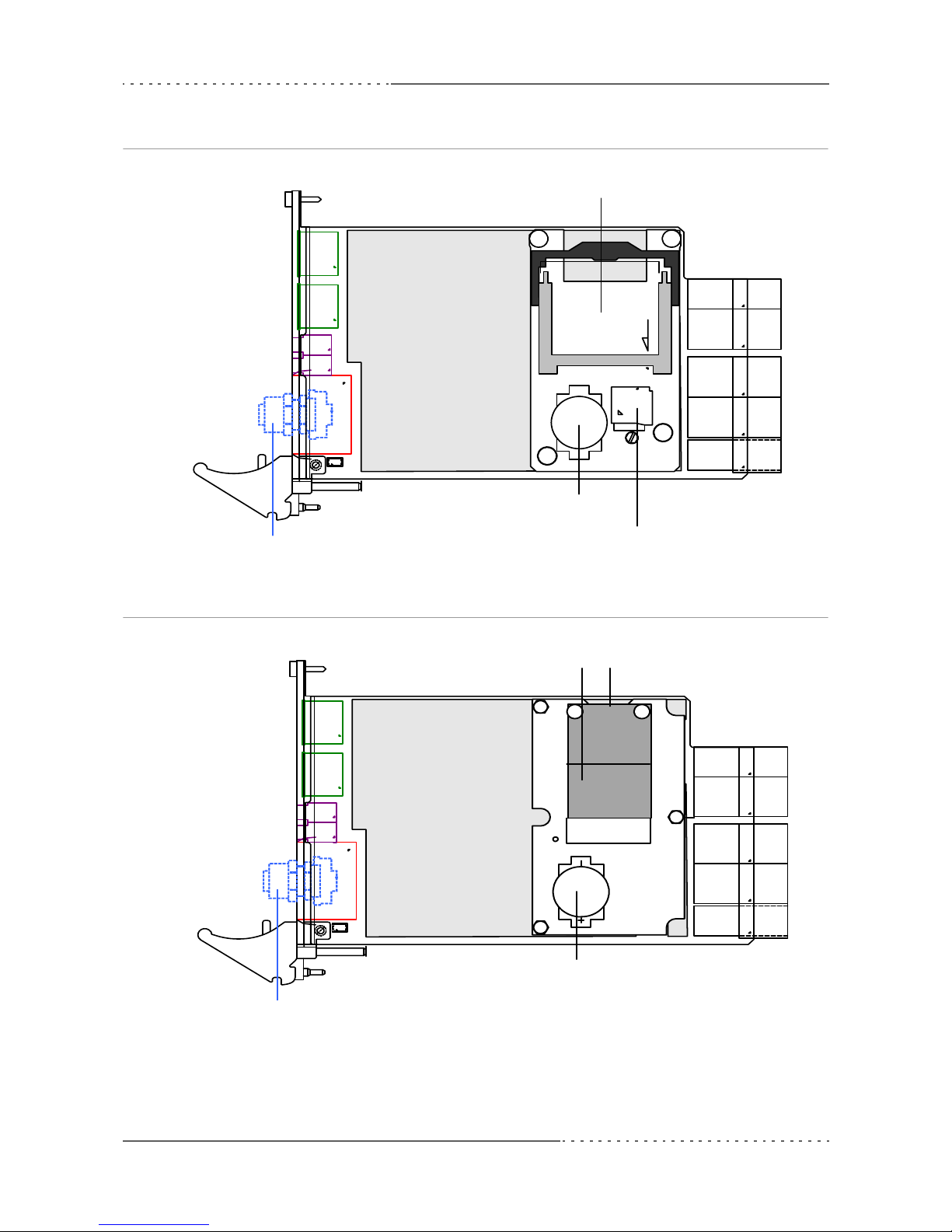
Figure 2. Map of the board – top view with CompactFlash (board versions 02G020-00 and -01)
Figure 3. Map of the board – top view with mSATA disk (board versions 02G020-02 and -03)
Display Port
Connectors
USB
Connectors
Ethernet
Connectors
Heat Sink
Battery
MicroSD
CompactFlash
M12 Connector for Ethernet(optional)
Display Port
Connectors
USB
Connectors
Ethernet
Connectors
Heat Sink
Battery
microSD (bottom)
M12 Connector for Ethernet (optional)
mSATA
Getting Started
MEN Mikro Elektronik GmbH 20
20G020-00 E5 – 2014-01-21
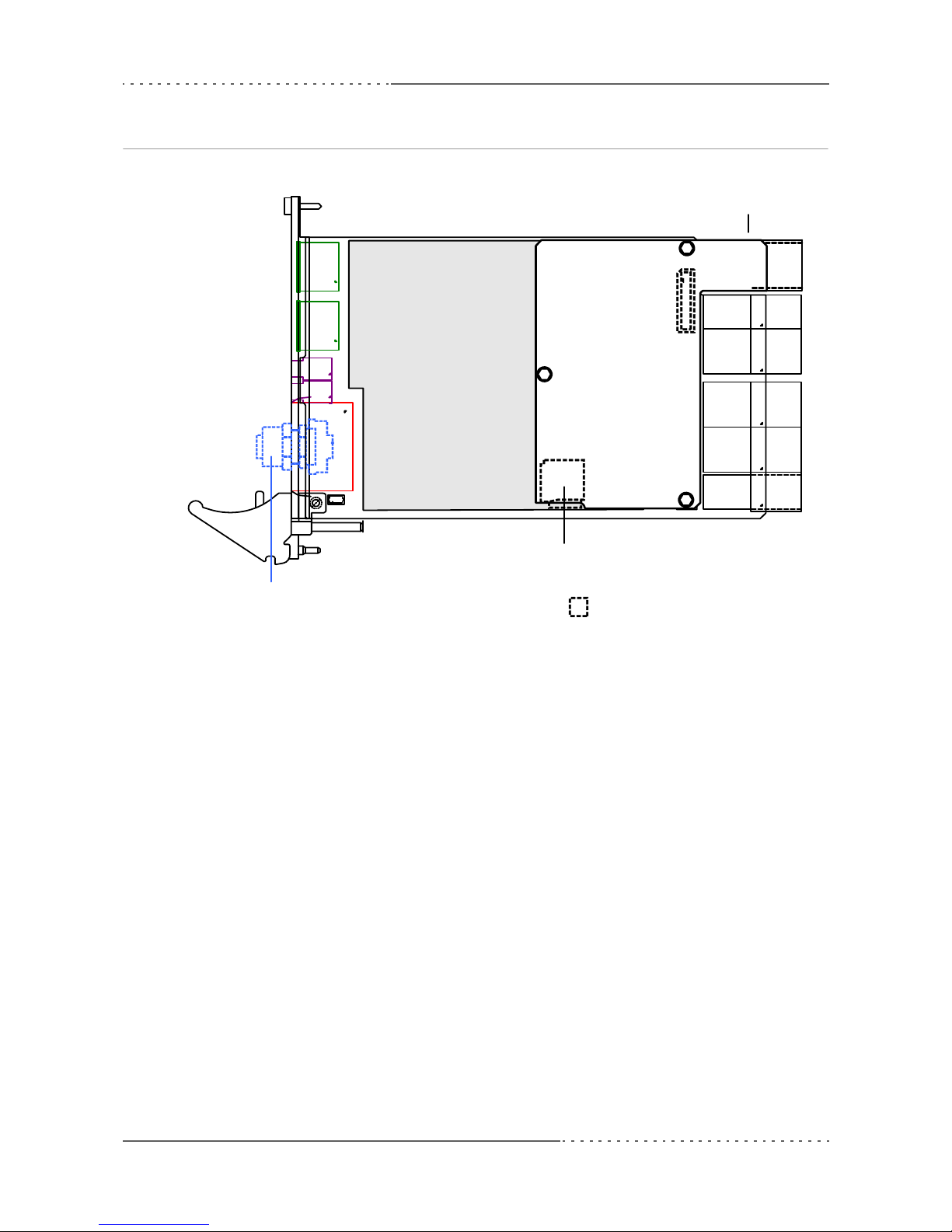
Figure 4. Map of the board – top view with Ethernet rear I/O card
Display Port
Connectors
USB
Connectors
Ethernet
Connectors
Heat Sink
M12 Connector for Ethernet (optional)
CompactPCI Serial
Connector P6
microSD Card Slot
Bottom side of Ethernet card
Table of contents
Other MEN Mikro Elektronik Motherboard manuals


Popular Motherboard manuals by other brands

Banana Pi
Banana Pi BPI-M1 manual

IEI Technology
IEI Technology KINO-PV-D4253-R10 Quick installation guide

Infineon
Infineon TriBoard TC3X5 user manual

GIGA-BYTE TECHNOLOGY
GIGA-BYTE TECHNOLOGY B550M AORUS PRO user manual

Linear Technology
Linear Technology DC861A-A quick start guide

Freetech
Freetech P6F135 user manual


