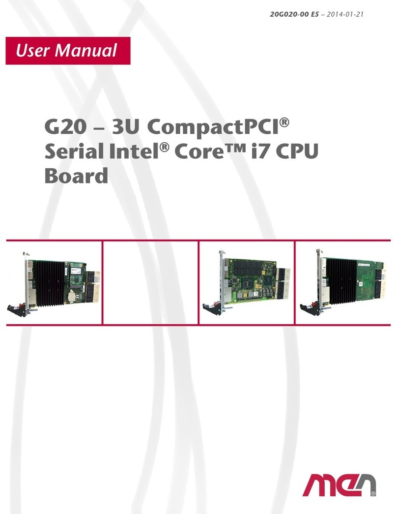
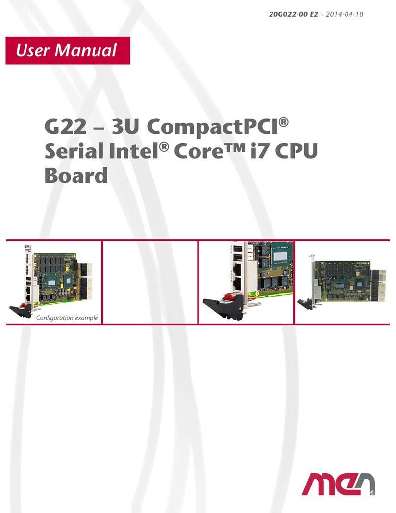
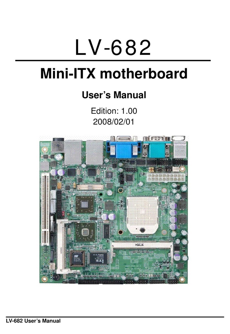
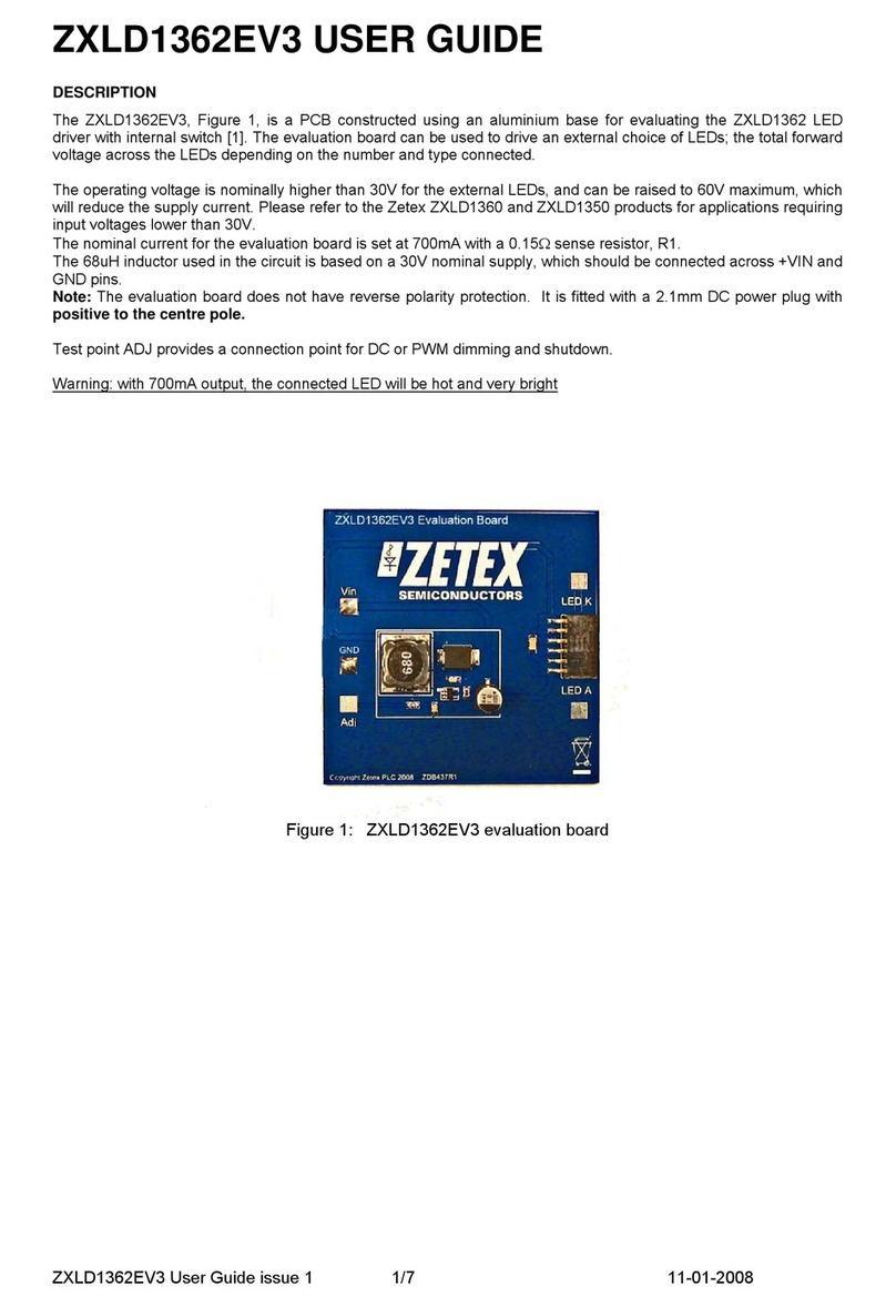
MEN Mikro Elektronik A14C - 6U VME64 MPC8540 User manual

®
Embedded Solutions
A14C – 6U VME64
MPC8540 SBC / PMC
20A014-00 E2 – 2007-08-16
User Manual
Configuration example

A14C – 6U VME64 MPC8540 SBC / PMC
MEN Mikro Elektronik GmbH 2
20A014-00 E2 – 2007-08-16
A14C – 6U VME64 MPC8540 SBC / PMC
The A14C is an advanced PowerPC® based single-board computer for embedded
applications. It features full VME64 support and it can be used as a master or a slave
in a VMEbus environment. The A14C provides 1 MB local shared SRAM for slave
access and communication between the local CPU and another VMEbus master.
The A14C is controlled by an MPC8540 integrated PowerPC® processor working
at 800 MHz. The SBC is equipped with a DDR SO-DIMM socket for data storage,
with NAND Flash for program storage as well as with non-volatile FRAM. The
board provides front-panel access for two Gigabit Ethernet, one fast Ethernet and
one COM via four RJ45 connectors. Four more UARTs are optionally accessible via
SA-Adapters™ for front connection.
Additional functionality such as graphics, touch, CAN, binary I/O etc. can be
realized as IP cores in FPGA for the needs of the individual application. The
corresponding PHYs are available via SA-Adapters™ on a transition module to the
rear.
The FPGA acts as a standard PCI device on the A14C. The FPGA functions are
loaded by software during power-up within less than 1 s. FPGA updates can be
carried out dynamically during operation.
In addition, the A14C can be equipped with PMC mezzanine cards supporting
64 bits/66 MHz as well as front I/O and rear I/O (PIM).
The A14C comes with MENMON™ support. This firmware/BIOS can be used for
bootstrapping operating systems (from disk, Flash or network), for hardware testing,
or for debugging applications without running any operating system.

Technical Data
MEN Mikro Elektronik GmbH 3
20A014-00 E2 – 2007-08-16
Technical Data
CPU
•PowerPC®
- MPC8540 PowerQUICC™ III
- 800MHz (666..833MHz optional)
- e500 PowerPC® core with SPE APU and MMU
- Integrated Northbridge and Southbridge
- High memory bandwidth
Memory
• 2x32KB L1 data and instruction cache, 256KB L2 cache / SRAM integrated in
MPC8540
• Up to 2GB SDRAM system memory
- SO-DIMM slot for SDRAM modules
- DDR2100 with or without ECC
- 133MHz memory bus frequency
• Up to 1GB soldered NAND Flash (and more), FPGA-controlled
• Up to 16MB additional SDRAM, FPGA-controlled, e.g. for video data and
NAND Flash firmware
• 8MB boot Flash
• 32KB non-volatile FRAM
• Serial EEPROM 4kbits for factory settings
Mass Storage
• Parallel IDE (PATA)
- One port for hard-disk drives
- Drive can be connected via ribbon cable or mounted directly on the CPU
board using MEN adapter kit (instead of PMC modules)
- Only one VMEbus slot needed even with hard disk
- PIO mode 0 support
• Up to 1GB soldered ATA NAND Flash (and more), FPGA-controlled
I/O
• Three Ethernet channels
- Two 10/100/1000Base-T Ethernet channels
- One 10/100Base-T Ethernet channel
- Three RJ45 connectors at front panel
- Two on-board LEDs to signal LAN Link and Activity
• One RS232 UART (COM1)
- One RJ45 connector at front panel
- Data rates up to 115.2kbits/s
- 16-byte transmit/receive buffer
- Handshake lines: CTS, RTS

Technical Data
MEN Mikro Elektronik GmbH 4
20A014-00 E2 – 2007-08-16
• One LVTTL UART (COM10)
-FPGA-controlled
- Accessible via rear I/O
- Data rates up to 115.2kbits/s
- 60-byte transmit/receive buffers
- Handshake lines: CTS, RTS; DCD, DSR, DTR; RI
• Quad UART (COM20..COM23)
- Physical interface using SA-Adapters™ via 10-pin ribbon cable on I/O con-
nector
- RS232..RS485, isolated or not: for free use in system (e. g. cable to front)
- Data rates up to 115.2kbits/s
- 128-byte transmit/receive buffer
- Handshake lines: CTS, RTS; DCD, DSR, DTR; RI
•GPIO
- 39 GPIO lines
-FPGA-controlled
- Accessible via rear I/O
Front Connections
• Three Ethernet (RJ45)
• COM1 (RJ45)
• COM20..COM23 (optional, instead of PMC modules, or in second front-panel
slot)
• PMC 0 and 1
Rear I/O
•COM10
•GPIO
• Mezzanine rear I/O: PMC 0
FPGA
• Standard factory FPGA configuration:
-Mainbusinterface
- 16Z070_IDEDISK - IDE controller for NAND Flash
- 16Z043_SDRAM - Additional SDRAM controller (16MB)
- 16Z023_IDENHS - IDE controller (PIO mode 0; non-hot-swap)
- 16Z025_UART - UART controller (controls COM10)
- 16Z034_GPIO - GPIO controller (40 lines, 5 IP cores)
• The FPGA offers the possibility to add customized I/O functionality. See FPGA.
Mezzanine Slots
•TwoPMCslots
- Compliant with PMC standard IEEE 1386.1
- Up to 64-bit/64-MHz, 3.3V V(I/O)
- PMC I/O module (PIM) support through J4

Technical Data
MEN Mikro Elektronik GmbH 5
20A014-00 E2 – 2007-08-16
Miscellaneous
• Real-time clock with GoldCap backup
• Power supervision and watchdog
• Reset button, GPIO-controlled, in ejector handle
Local PCI Bus
• 32-bit/33-MHz, 3.3V V(I/O)
• Compliant with PCI Specification 2.2
VMEbus
• Compliant with VME64 Specification
• Slot-1 function with auto-detection
•Master
- D08(EO):D16:D32:D64:A16:A24:A32:ADO:BLT:RMW
•Slave
- D08(EO):D16:D32:D64:A16:A24:A32:BLT:RMW
• 1MB shared fast SRAM
•DMA
• Mailbox functionality
• Interrupter D08(O):I(7-1):ROAK
• Interrupt handler D08(O):IH(7-1)
• Single level 3 fair requester
• Single level 3 arbiter
• Bus timer
• Location Monitor
• Performance
- Coupled read/write D32 non-block transfer rate 6.5 MB/s
- DMA read/write D32 BLT transfer rate 12.1 MB/s
- DMA read/write D64 MBLT transfer rate 25 MB/s
Electrical Specifications
• Supply voltage/power consumption:
- +5V (-3%/+5%), 3A typ.
- +12V (-5%/+5%), only provided for PMCs that need 12V
- -12V (-5%/+5%), only provided for PMCs that need 12V
• MTBF: 92,800h @ 40°C (derived from MIL-HDBK-217F)
Mechanical Specifications
• Dimensions: standard double Eurocard, 233.3mm x 160mm
• Weight (without PMC modules): 450g

Technical Data
MEN Mikro Elektronik GmbH 6
20A014-00 E2 – 2007-08-16
Environmental Specifications
• Temperature range (operation):
- 0..+60°C
- Airflow: min. 10m³/h
• Temperature range (storage): -40..+85°C
• Relative humidity (operation): max. 95% non-condensing
• Relative humidity (storage): max. 95% non-condensing
• Altitude: -300m to + 3,000m
• Shock: 15g/11ms
• Bump: 10g/16ms
• Vibration (sinusoidal): 2g/10..150Hz
• Conformal coating on request
Safety
• PCB manufactured with a flammability rating of 94V-0 by UL recognized manu-
facturers
EMC
• Tested according to EN 55022 (radio disturbance), IEC1000-4-2 (ESD) and
IEC1000-4-4 (burst) with regard to CE conformity
BIOS
•MENMON™
Software Support
• VxWorks®
• Linux (ELinOS)
• QNX®
• For more information on supported operating system versions and drivers see
online data sheet.

Block Diagram
MEN Mikro Elektronik GmbH 7
20A014-00 E2 – 2007-08-16
Block Diagram
PowerPC®
MPC8540
Boot Flash FRAM
SDRAM
Main
(SO-DIMM)
EEPROM
RTC
Watchdog
Ethernet
1000Base-T
Ethernet
1000Base-T
Ethernet
100Base-T
RS232 COM1
F
F
F
FPGA
VME
P2
VME
P1
SDRAM
Additional NAND
Flash
Quad UART
COM20..23 B
PCI-toPCI
Bridge
PCI-to-VMEbus
Bridge
SSRAM
PMC 1
PMC 0
F
F
PCI
R
F
GPIO
COM10
F
SA
IDE B
F
SA
F
SA
F
SA
F
B
Front Panel
On Board
RRear I/O
Option

Configuration Options
MEN Mikro Elektronik GmbH 8
20A014-00 E2 – 2007-08-16
Configuration Options
CPU
•Type
- MPC8540
- MPC8560
•Clock
- 666..833 MHz
Memory
•SystemRAM
- 256 MB, 512 MB, 1 GB or 2 GB
- With or without ECC
• NAND Flash
- 0 MB up to maximum available
• Additional SDRAM
- 0 MB or 16 MB
•FRAM
- 0 MB or 32 MB
•BootFlash
- 8 MB or 16 MB
I/O
• Quad UART (COM20..23)
- Direct on-board connection via 10-pin connectors, instead of PMCs
• Front Connections
- D-Sub instead of RJ45 connectors
Mezzanine Slots
• 2 PMC
• 3 PC-MIP®
Operation Temperature
• 0..+60°C
Please note that some of these options may only be available for large volumes.
Please ask our sales staff for more information.

FPGA
MEN Mikro Elektronik GmbH 9
20A014-00 E2 – 2007-08-16
FPGA
FPGA Capabilities
• FPGA Altera® Cyclone™ EP1C12
- 12,060 logic elements
- 239,616 total RAM bits
• Connection
- Available pin count: 47 pins
- Functions available e.g. via I/O connector
Flexible Configuration
• This MEN board offers the possibility to add customized I/O functionality in
FPGA.
• It depends on the board type, pin counts and number of logic elements which IP
cores make sense and/or can be implemented. Please contact MEN for informa-
tion on feasibility.
• Depending on the hardware platform, SA-Adapters™ can be used to realize the
physical lines.
MEN IP Cores
• MEN has a large number of standard IP cores to choose from.
•Examples:
- IDE (e.g. PIO mode 0, UDMA mode 5)
-UARTs
- CAN bus
- Display control
-...
• For IP cores developed by MEN please refer to our IP core overview.
-IP Core compare chart (PDF)
• MEN also offers development of new (customized) IP cores.
Third-Party IP Cores
• Third-party IP cores can also be used in combination with MEN IP cores.
•Examples:
-www.altera.com
-www.opencores.org
FPGA Design Environment
• Altera® offers free download of Quartus® II Web Edition
- Complete environment for FPGA and CPLD design
- Includes schematic- and text-based design entry
- Integrated VHDL and Verilog HDL synthesis and support for third-party syn-
thesis software
- SOPC Builder system generation software
- Place-and-route, verification, and programming
» Altera® Quartus® II Web Edition FPGA design tool

Product Safety
MEN Mikro Elektronik GmbH 10
20A014-00 E2 – 2007-08-16
Product Safety
Electrostatic Discharge (ESD)
Computer boards and components contain electrostatic sensitive devices.
Electrostatic discharge (ESD) can damage components. To protect the board and
other components against damage from static electricity, you should follow some
precautions whenever you work on your computer.
• Power down and unplug your computer system when working on the inside.
• Hold components by the edges and try not to touch the IC chips, leads, or cir-
cuitry.
• Use a grounded wrist strap before handling computer components.
• Place components on a grounded antistatic pad or on the bag that came with the
component whenever the components are separated from the system.
• Store the board only in its original ESD-protected packaging. Retain the original
packaging in case you need to return the board to MEN for repair.
!

About this Document
MEN Mikro Elektronik GmbH 11
20A014-00 E2 – 2007-08-16
About this Document
This user manual describes the hardware functions of the board, connection of
peripheral devices and integration into a system. It also provides additional
information for special applications and configurations of the board.
The manual does not include detailed information on individual components (data
sheets etc.). A list of literature is given in the appendix.
History
Conventions
This sign marks important notes or warnings concerning proper functionality of the
product described in this document. You should read them in any case.
Folder, file and function names are printed in italics.
Bold type is used for emphasis.
A monospaced font type is used for hexadecimal numbers, listings, C function
descriptions or wherever appropriate. Hexadecimal numbers are preceded by "0x".
Hyperlinks are printed in blue color.
The globe will show you where hyperlinks lead directly to the Internet, so you can
look for the latest information online.
Signal names followed by "#" or preceded by a slash ("/") indicate that this signal is
either active low or that it becomes active at a falling edge.
Signal directions in signal mnemonics tables generally refer to the corresponding
board or component, "in" meaning "to the board or component", "out" meaning
"coming from it".
Vertical lines on the outer margin signal technical changes to the previous edition of
the document.
Edition Comments Technical Content Date of Issue
E1 First edition H. Schubert, D. Hof-
bauer, T. Schnürer
2006-01-17
E2 General update, switching of
rear I/O documented, address
table adapted to MENMON
rev. 1.7
H. Schubert, D. Hof-
bauer, T. Schnürer
2007-08-16
!
italics
bold
monospace
hyperlink
IRQ
#
/IRQ
in/out

About this Document
MEN Mikro Elektronik GmbH 12
20A014-00 E2 – 2007-08-16
Legal Information
MEN Mikro Elektronik reserves the right to make changes without further notice to any products herein. MEN makes no
warranty, representation or guarantee regarding the suitability of its products for any particular purpose, nor does MEN assume
any liability arising out of the application or use of any product or circuit, and specifically disclaims any and all liability,
including without limitation consequential or incidental damages.
"Typical" parameters can and do vary in different applications. All operating parameters, including "Typicals" must be
validated for each customer application by customer's technical experts.
MEN does not convey any license under its patent rights nor the rights of others.
Unless agreed otherwise, MEN products are not designed, intended, or authorized for use as components in systems intended
for surgical implant into the body, or other applications intended to support or sustain life, or for any other application in which
the failure of the MEN product could create a situation where personal injury or death may occur. Should Buyer purchase or
use MEN products for any such unintended or unauthorized application, Buyer shall indemnify and hold MEN and its officers,
employees, subsidiaries, affiliates, and distributors harmless against all claims, costs, damages, and expenses, and reasonable
attorney fees arising out of, directly or indirectly, any claim of personal injury or death associated with such unintended or
unauthorized use, even if such claim alleges that MEN was negligent regarding the design or manufacture of the part.
Unless agreed otherwise, the products of MEN Mikro Elektronik are not suited for use in nuclear reactors and for application
in medical appliances used for therapeutical purposes. Application of MEN products in such plants is only possible after the
user has precisely specified the operation environment and after MEN Mikro Elektronik has consequently adapted and
released the product.
ESM™, MDIS™, MDIS4™, MENMON™, M-Module™, M-Modules™, SA-Adapter™, SA-Adapters™, UBox™ and
USM™ are trademarks of MEN Mikro Elektronik GmbH. PC-MIP® is a registered trademark of MEN Micro, Inc. and SBS
Technologies, Inc. MEN Mikro Elektronik®, ESMexpress® and the MEN logo are registered trademarks of MEN Mikro
Elektronik GmbH.
Altera®, Avalon®, Cyclone™, Nios® and Quartus® are trademarks or registered trademarks of Altera Corp.
Freescale™ and PowerQUICC™ are trademarks of Freescale Semiconductor, Inc.
PowerPC® is a registered trademark of IBM Corp.
Microsoft® and Windows® are registered trademarks of Microsoft Corp. Windows® Vista™ is a trademark of Microsoft Corp.
OS-9®, OS-9000® and SoftStax® are registered trademarks of RadiSys Microware Communications Software Division, Inc.
FasTrak™ and Hawk™ are trademarks of RadiSys Microware Communications Software Division, Inc. RadiSys® is a
registered trademark of RadiSys Corporation.
QNX® is a registered trademark of QNX Ltd.
CompactFlash® is a registered trademark of SanDisk Corp.
Tornado® and VxWorks® are registered trademarks of Wind River Systems, Inc.
All other products or services mentioned in this publication are identified by the trademarks, service marks, or product names
as designated by the companies who market those products. The trademarks and registered trademarks are held by the
companies producing them. Inquiries concerning such trademarks should be made directly to those companies. All other brand
or product names are trademarks or registered trademarks of their respective holders.
Information in this document has been carefully checked and is believed to be accurate as of the date of publication; however,
no responsibility is assumed for inaccuracies. MEN Mikro Elektronik accepts no liability for consequential or incidental
damages arising from the use of its products and reserves the right to make changes on the products herein without notice to
improve reliability, function or design. MEN Mikro Elektronik does not assume any liability arising out of the application or
use of the products described in this document.
Copyright © 2007 MEN Mikro Elektronik GmbH. All rights reserved.
Please recycle
Germany
MEN Mikro Elektronik GmbH
Neuwieder Straße 5-7
90411 Nuremberg
Phone +49-911-99 33 5-0
Fax +49-911-99 33 5-901
E-mail [email protected]
www.men.de
France
MEN Mikro Elektronik SA
18, rue René Cassin
ZA de la Châtelaine
74240 Gaillard
Phone +33 (0) 450-955-312
Fax +33 (0) 450-955-211
E-mail info@men-france.fr
www.men-france.fr
USA
MEN Micro, Inc.
24 North Main Street
Ambler, PA 19002
Phone (215) 542-9575
Fax (215) 542-9577
E-mail [email protected]
www.menmicro.com

Contents
MEN Mikro Elektronik GmbH 13
20A014-00 E2 – 2007-08-16
Contents
1 Getting Started . . . . . . . . . . . . . . . . . . . . . . . . . . . . . . . . . . . . . . . . . . . . . . . . 19
1.1 Maps of the Board . . . . . . . . . . . . . . . . . . . . . . . . . . . . . . . . . . . . . . . . 19
1.2 Configuring the Hardware . . . . . . . . . . . . . . . . . . . . . . . . . . . . . . . . . . 21
1.3 Integrating the Board into a System . . . . . . . . . . . . . . . . . . . . . . . . . . 22
1.4 Installing Operating System Software. . . . . . . . . . . . . . . . . . . . . . . . . 23
2 Functional Description . . . . . . . . . . . . . . . . . . . . . . . . . . . . . . . . . . . . . . . . . . 24
2.1 Power Supply. . . . . . . . . . . . . . . . . . . . . . . . . . . . . . . . . . . . . . . . . . . . 24
2.1.1 Watchdog. . . . . . . . . . . . . . . . . . . . . . . . . . . . . . . . . . . . . . . . 24
2.2 Clock Supply . . . . . . . . . . . . . . . . . . . . . . . . . . . . . . . . . . . . . . . . . . . . 24
2.3 Real-Time Clock . . . . . . . . . . . . . . . . . . . . . . . . . . . . . . . . . . . . . . . . . 24
2.4 PowerPC CPU . . . . . . . . . . . . . . . . . . . . . . . . . . . . . . . . . . . . . . . . . . . 25
2.4.1 General . . . . . . . . . . . . . . . . . . . . . . . . . . . . . . . . . . . . . . . . . 25
2.4.2 Thermal Considerations . . . . . . . . . . . . . . . . . . . . . . . . . . . . 25
2.5 Bus Structure . . . . . . . . . . . . . . . . . . . . . . . . . . . . . . . . . . . . . . . . . . . . 26
2.5.1 Host-to-PCI Bridge . . . . . . . . . . . . . . . . . . . . . . . . . . . . . . . . 26
2.5.2 Local PCI Bus . . . . . . . . . . . . . . . . . . . . . . . . . . . . . . . . . . . . 26
2.5.3 PCI-to-PCI Bridge. . . . . . . . . . . . . . . . . . . . . . . . . . . . . . . . . 26
2.5.4 PCI-to-VMEbus Bridge . . . . . . . . . . . . . . . . . . . . . . . . . . . . 26
2.6 Memory . . . . . . . . . . . . . . . . . . . . . . . . . . . . . . . . . . . . . . . . . . . . . . . . 27
2.6.1 DRAM System Memory . . . . . . . . . . . . . . . . . . . . . . . . . . . . 27
2.6.2 Boot Flash . . . . . . . . . . . . . . . . . . . . . . . . . . . . . . . . . . . . . . . 27
2.6.3 NAND Flash . . . . . . . . . . . . . . . . . . . . . . . . . . . . . . . . . . . . . 27
2.6.4 FRAM . . . . . . . . . . . . . . . . . . . . . . . . . . . . . . . . . . . . . . . . . . 27
2.6.5 Additional SDRAM . . . . . . . . . . . . . . . . . . . . . . . . . . . . . . . 27
2.6.6 EEPROM. . . . . . . . . . . . . . . . . . . . . . . . . . . . . . . . . . . . . . . . 27
2.7 IDE Interface . . . . . . . . . . . . . . . . . . . . . . . . . . . . . . . . . . . . . . . . . . . . 28
2.7.1 Connection . . . . . . . . . . . . . . . . . . . . . . . . . . . . . . . . . . . . . . 28
2.7.2 Installing a Hard Disk . . . . . . . . . . . . . . . . . . . . . . . . . . . . . . 30
2.8 Ethernet Interfaces. . . . . . . . . . . . . . . . . . . . . . . . . . . . . . . . . . . . . . . . 32
2.8.1 Connection . . . . . . . . . . . . . . . . . . . . . . . . . . . . . . . . . . . . . . 32
2.8.2 General . . . . . . . . . . . . . . . . . . . . . . . . . . . . . . . . . . . . . . . . . 34
2.8.3 10Base-T . . . . . . . . . . . . . . . . . . . . . . . . . . . . . . . . . . . . . . . . 34
2.8.4 100Base-T . . . . . . . . . . . . . . . . . . . . . . . . . . . . . . . . . . . . . . . 34
2.8.5 1000Base-T . . . . . . . . . . . . . . . . . . . . . . . . . . . . . . . . . . . . . . 34
2.9 UART COM1 Interface . . . . . . . . . . . . . . . . . . . . . . . . . . . . . . . . . . . . 35
2.10 UART COM10 Interface . . . . . . . . . . . . . . . . . . . . . . . . . . . . . . . . . . . 37
2.11 UART COM20..COM23 Interfaces. . . . . . . . . . . . . . . . . . . . . . . . . . . 38
2.11.1 Connection via 40-pin Connector . . . . . . . . . . . . . . . . . . . . . 39
2.11.2 Connection via 10-pin SA-Adapter Connectors . . . . . . . . . . 42
2.12 GPIO . . . . . . . . . . . . . . . . . . . . . . . . . . . . . . . . . . . . . . . . . . . . . . . . . . 45
2.13 PMC Slots . . . . . . . . . . . . . . . . . . . . . . . . . . . . . . . . . . . . . . . . . . . . . . 46
2.13.1 Installing a PMC Mezzanine Module . . . . . . . . . . . . . . . . . . 47

Contents
MEN Mikro Elektronik GmbH 14
20A014-00 E2 – 2007-08-16
2.14 Board-to-Board I/O Connector . . . . . . . . . . . . . . . . . . . . . . . . . . . . . . 48
2.15 Reset Button . . . . . . . . . . . . . . . . . . . . . . . . . . . . . . . . . . . . . . . . . . . . 51
2.16 VMEbus Interface . . . . . . . . . . . . . . . . . . . . . . . . . . . . . . . . . . . . . . . . 52
2.16.1 PCI Configuration Space Registers. . . . . . . . . . . . . . . . . . . . 53
2.16.2 Runtime Registers . . . . . . . . . . . . . . . . . . . . . . . . . . . . . . . . . 54
2.16.3 VMEbus Master Mapping. . . . . . . . . . . . . . . . . . . . . . . . . . . 55
2.16.4 VME Slave Mapping. . . . . . . . . . . . . . . . . . . . . . . . . . . . . . . 56
2.16.5 SRAM . . . . . . . . . . . . . . . . . . . . . . . . . . . . . . . . . . . . . . . . . . 56
2.16.6 Slot-1 Function . . . . . . . . . . . . . . . . . . . . . . . . . . . . . . . . . . . 57
2.16.7 VMEbus Master Interface . . . . . . . . . . . . . . . . . . . . . . . . . . . 58
2.16.8 VMEbus Slave Interface . . . . . . . . . . . . . . . . . . . . . . . . . . . . 62
2.16.9 VMEbus Requester . . . . . . . . . . . . . . . . . . . . . . . . . . . . . . . . 67
2.16.10 VMEbus Interrupt Handler . . . . . . . . . . . . . . . . . . . . . . . . . . 68
2.16.11 VMEbus Interrupter . . . . . . . . . . . . . . . . . . . . . . . . . . . . . . . 69
2.16.12 A32 Address Mode . . . . . . . . . . . . . . . . . . . . . . . . . . . . . . . . 70
2.16.13 Mailbox . . . . . . . . . . . . . . . . . . . . . . . . . . . . . . . . . . . . . . . . . 71
2.16.14 Location Monitor . . . . . . . . . . . . . . . . . . . . . . . . . . . . . . . . . 72
2.16.15 DMA Controller . . . . . . . . . . . . . . . . . . . . . . . . . . . . . . . . . . 74
2.16.16 Connection . . . . . . . . . . . . . . . . . . . . . . . . . . . . . . . . . . . . . . 76
3 FPGA . . . . . . . . . . . . . . . . . . . . . . . . . . . . . . . . . . . . . . . . . . . . . . . . . . . . . . . . 82
3.1 General . . . . . . . . . . . . . . . . . . . . . . . . . . . . . . . . . . . . . . . . . . . . . . . . 82
3.2 System Unit . . . . . . . . . . . . . . . . . . . . . . . . . . . . . . . . . . . . . . . . . . . . . 83
3.2.1 Functional Description . . . . . . . . . . . . . . . . . . . . . . . . . . . . . 83
3.2.2 Address Organization . . . . . . . . . . . . . . . . . . . . . . . . . . . . . . 85
3.3 Standard Factory FPGA Configuration . . . . . . . . . . . . . . . . . . . . . . . . 92
3.3.1 IP Cores. . . . . . . . . . . . . . . . . . . . . . . . . . . . . . . . . . . . . . . . . 92
3.3.2 FPGA Configuration Table . . . . . . . . . . . . . . . . . . . . . . . . . . 92
4 MENMON . . . . . . . . . . . . . . . . . . . . . . . . . . . . . . . . . . . . . . . . . . . . . . . . . . . . 93
4.1 General . . . . . . . . . . . . . . . . . . . . . . . . . . . . . . . . . . . . . . . . . . . . . . . . 93
4.1.1 State Diagram . . . . . . . . . . . . . . . . . . . . . . . . . . . . . . . . . . . . 94
4.2 Interacting with MENMON . . . . . . . . . . . . . . . . . . . . . . . . . . . . . . . . 96
4.2.1 Entering the Setup Menu/Command Line . . . . . . . . . . . . . . 96
4.3 Configuring MENMON for Automatic Boot . . . . . . . . . . . . . . . . . . . 96
4.4 Updating Boot Flash and NAND Flash . . . . . . . . . . . . . . . . . . . . . . . . 97
4.4.1 Update via the Serial Console using SERDL . . . . . . . . . . . . 97
4.4.2 Update from Network using NDL. . . . . . . . . . . . . . . . . . . . . 97
4.4.3 Update via Program Update Menu . . . . . . . . . . . . . . . . . . . . 97
4.4.4 Automatic Update Check . . . . . . . . . . . . . . . . . . . . . . . . . . . 98
4.5 Diagnostic Tests. . . . . . . . . . . . . . . . . . . . . . . . . . . . . . . . . . . . . . . . . . 99
4.5.1 Ethernet . . . . . . . . . . . . . . . . . . . . . . . . . . . . . . . . . . . . . . . . . 99
4.5.2 SDRAM and FRAM . . . . . . . . . . . . . . . . . . . . . . . . . . . . . . 100
4.5.3 EEPROM. . . . . . . . . . . . . . . . . . . . . . . . . . . . . . . . . . . . . . . 101
4.5.4 IDE/NAND Flash . . . . . . . . . . . . . . . . . . . . . . . . . . . . . . . . 102

Contents
MEN Mikro Elektronik GmbH 15
20A014-00 E2 – 2007-08-16
4.5.5 COM1 Port . . . . . . . . . . . . . . . . . . . . . . . . . . . . . . . . . . . . . 102
4.5.6 Primary/Secondary MENMON. . . . . . . . . . . . . . . . . . . . . . 103
4.5.7 Hardware Monitor Test . . . . . . . . . . . . . . . . . . . . . . . . . . . . 103
4.5.8 RTC . . . . . . . . . . . . . . . . . . . . . . . . . . . . . . . . . . . . . . . . . . . 103
4.6 MENMON Configuration and Organization . . . . . . . . . . . . . . . . . . . 104
4.6.1 Consoles . . . . . . . . . . . . . . . . . . . . . . . . . . . . . . . . . . . . . . . 104
4.6.2 Video Modes . . . . . . . . . . . . . . . . . . . . . . . . . . . . . . . . . . . . 104
4.6.3 Abort Pin . . . . . . . . . . . . . . . . . . . . . . . . . . . . . . . . . . . . . . . 104
4.6.4 MENMON Memory Map . . . . . . . . . . . . . . . . . . . . . . . . . . 105
4.6.5 MENMON BIOS Logical Units . . . . . . . . . . . . . . . . . . . . . 106
4.6.6 System Parameters . . . . . . . . . . . . . . . . . . . . . . . . . . . . . . . 107
4.7 MENMON Commands . . . . . . . . . . . . . . . . . . . . . . . . . . . . . . . . . . . 113
5 Organization of the Board . . . . . . . . . . . . . . . . . . . . . . . . . . . . . . . . . . . . . . 115
5.1 Memory Mappings . . . . . . . . . . . . . . . . . . . . . . . . . . . . . . . . . . . . . . 115
5.2 Interrupt Handling . . . . . . . . . . . . . . . . . . . . . . . . . . . . . . . . . . . . . . . 116
5.3 SMB Devices. . . . . . . . . . . . . . . . . . . . . . . . . . . . . . . . . . . . . . . . . . . 116
5.4 PCI Devices on Bus 0 . . . . . . . . . . . . . . . . . . . . . . . . . . . . . . . . . . . . 117
6 Appendix . . . . . . . . . . . . . . . . . . . . . . . . . . . . . . . . . . . . . . . . . . . . . . . . . . . . 118
6.1 Literature and Web Resources . . . . . . . . . . . . . . . . . . . . . . . . . . . . . . 118
6.1.1 PowerPC . . . . . . . . . . . . . . . . . . . . . . . . . . . . . . . . . . . . . . . 118
6.1.2 IDE . . . . . . . . . . . . . . . . . . . . . . . . . . . . . . . . . . . . . . . . . . . 118
6.1.3 Ethernet . . . . . . . . . . . . . . . . . . . . . . . . . . . . . . . . . . . . . . . . 118
6.1.4 PMC . . . . . . . . . . . . . . . . . . . . . . . . . . . . . . . . . . . . . . . . . . 119
6.1.5 PCI-104 . . . . . . . . . . . . . . . . . . . . . . . . . . . . . . . . . . . . . . . . 119
6.1.6 VMEbus . . . . . . . . . . . . . . . . . . . . . . . . . . . . . . . . . . . . . . . 119
6.2 Finding out the Board’s Article Number, Revision and Serial
Number . . . . . . . . . . . . . . . . . . . . . . . . . . . . . . . . . . . . . . . . . . . . . . . 119

MEN Mikro Elektronik GmbH 16
20A014-00 E2 – 2007-08-16
Figures
Figure 1. Map of the Board – front view . . . . . . . . . . . . . . . . . . . . . . . . . . . . . . . 19
Figure 2. Map of the Board – top view . . . . . . . . . . . . . . . . . . . . . . . . . . . . . . . . 20
Figure 3. Position of fuse for IDE protection. . . . . . . . . . . . . . . . . . . . . . . . . . . . 29
Figure 4. Installing SA-Adapters on A14C directly . . . . . . . . . . . . . . . . . . . . . . 43
Figure 5. Position of fuse for COM20..COM23 protection. . . . . . . . . . . . . . . . . 44
Figure 6. Installing a PMC mezzanine module . . . . . . . . . . . . . . . . . . . . . . . . . . 47
Figure 7. Position of reset button . . . . . . . . . . . . . . . . . . . . . . . . . . . . . . . . . . . . . 51
Figure 8. FPGA – Block diagram . . . . . . . . . . . . . . . . . . . . . . . . . . . . . . . . . . . . 82
Figure 9. MENMON – State diagram, Degraded Mode/Full Mode . . . . . . . . . . 94
Figure 10. MENMON – State diagram, Main State . . . . . . . . . . . . . . . . . . . . . . . 95
Figure 11. Label giving the board’s article number, revision and serial number 119

MEN Mikro Elektronik GmbH 17
20A014-00 E2 – 2007-08-16
Tables
Table 1. Pin assignment of 44-pin IDE plug connector . . . . . . . . . . . . . . . . . . . 28
Table 2. Signal mnemonics of 44-pin IDE plug connector . . . . . . . . . . . . . . . . 29
Table 3. Signal mnemonics of Ethernet 10Base-T/100Base-TX/1000Base-TX
interfaces. . . . . . . . . . . . . . . . . . . . . . . . . . . . . . . . . . . . . . . . . . . . . . . . 32
Table 4. Pin assignment of 8-pin RJ45 Ethernet 10Base-T/100Base-TX/
1000Base-TX connectors (LAN1..3) . . . . . . . . . . . . . . . . . . . . . . . . . . 32
Table 5. Pin assignment of 9-pin D-Sub 10Base-T/100Base-TX plug connector
(LAN1 and LAN2) . . . . . . . . . . . . . . . . . . . . . . . . . . . . . . . . . . . . . . . . 33
Table 6. Pin assignment of 9-pin D-Sub 10Base-T/100Base-TX plug connector
(LAN3 and COM1) . . . . . . . . . . . . . . . . . . . . . . . . . . . . . . . . . . . . . . . 33
Table 7. Signal mnemonics of UART COM1 interface . . . . . . . . . . . . . . . . . . . 35
Table 8. Pin assignment of 8-pin RJ45 UART connector (COM1) . . . . . . . . . . 35
Table 9. Pin assignment of 9-pin D-Sub COM1/LAN3 plug connector . . . . . . 36
Table 10. Signal mnemonics for UART COM20..COM23 interfaces . . . . . . . . . 38
Table 11. Pin assignment of the 40-pin UART COM20..COM23 connector . . . 39
Table 12. Pin assignment of the 10-pin UART COM20..COM23 connectors. . . 42
Table 13. Assignment of 16Z034_GPIO controllers . . . . . . . . . . . . . . . . . . . . . . 45
Table 14. Pin assignment of I/O connector J2 – factory standard FPGA
configuration. . . . . . . . . . . . . . . . . . . . . . . . . . . . . . . . . . . . . . . . . . . . . 49
Table 15. Signal mnemonics of I/O connector J2 – factory standard FPGA
configuration. . . . . . . . . . . . . . . . . . . . . . . . . . . . . . . . . . . . . . . . . . . . . 50
Table 16. VMEbus interface PCI configuration space registers. . . . . . . . . . . . . . 53
Table 17. VMEbus runtime registers . . . . . . . . . . . . . . . . . . . . . . . . . . . . . . . . . . 54
Table 18. VMEbus interface BAR 0. . . . . . . . . . . . . . . . . . . . . . . . . . . . . . . . . . . 55
Table 19. VMEbus interface BAR1 . . . . . . . . . . . . . . . . . . . . . . . . . . . . . . . . . . . 55
Table 20. VMEbus interface BAR2 . . . . . . . . . . . . . . . . . . . . . . . . . . . . . . . . . . . 55
Table 21. VMEbus interface BAR3 . . . . . . . . . . . . . . . . . . . . . . . . . . . . . . . . . . . 55
Table 22. VMEbus interface BAR4 . . . . . . . . . . . . . . . . . . . . . . . . . . . . . . . . . . . 55
Table 23. VMEbus slave address windows . . . . . . . . . . . . . . . . . . . . . . . . . . . . . 56
Table 24. VMEbus interface valid combinations for byte enables supported by PCI-
to-VME bridge . . . . . . . . . . . . . . . . . . . . . . . . . . . . . . . . . . . . . . . . . . . 59
Table 25. VMEbus master Address Modifier codes. . . . . . . . . . . . . . . . . . . . . . . 61
Table 26. VMEbus slave Address Modifier codes . . . . . . . . . . . . . . . . . . . . . . . . 66
Table 27. Pin assignment of VME64 connector P1 . . . . . . . . . . . . . . . . . . . . . . . 76
Table 28. Pin assignment of VMEbus rear I/O connector P2 – PMC signals . . . 78
Table 29. Signal mnemonics of VMEbus rear I/O connector P2 – PMC 0 . . . . . 79
Table 30. Pin assignment of VMEbus rear I/O connector P2 – FPGA I/O signals80
Table 31. Signal mnemonics of VMEbus rear I/O connector P2 – FPGA I/O. . . 81
Table 32. FPGA – Address map. . . . . . . . . . . . . . . . . . . . . . . . . . . . . . . . . . . . . . 85
Table 33. FPGA – Factory standard configuration table for A14C . . . . . . . . . . . 92
Table 34. MENMON – Program update files and locations . . . . . . . . . . . . . . . . 97
Table 35. MENMON – Diagnostic tests: Ethernet. . . . . . . . . . . . . . . . . . . . . . . . 99

MEN Mikro Elektronik GmbH 18
20A014-00 E2 – 2007-08-16
Table 36. MENMON – Diagnostic tests: SDRAM and FRAM . . . . . . . . . . . . . 100
Table 37. MENMON – Diagnostic tests: EEPROM . . . . . . . . . . . . . . . . . . . . . 101
Table 38. MENMON – Diagnostic tests: IDE/NAND Flash . . . . . . . . . . . . . . . 102
Table 39. MENMON – Diagnostic tests: COM1 Port . . . . . . . . . . . . . . . . . . . . 102
Table 40. MENMON – Diagnostic tests: Primary/Secondary MENMON . . . . 103
Table 41. MENMON – Diagnostic tests: Hardware Monitor. . . . . . . . . . . . . . . 103
Table 42. MENMON – Diagnostic tests: RTC. . . . . . . . . . . . . . . . . . . . . . . . . . 103
Table 43. MENMON – System parameters for console selection . . . . . . . . . . . 104
Table 44. MENMON – Address map (full-featured mode) . . . . . . . . . . . . . . . . 105
Table 45. MENMON – Boot Flash memory map . . . . . . . . . . . . . . . . . . . . . . . 105
Table 46. MENMON – Controller Logical Units (CLUNs). . . . . . . . . . . . . . . . 106
Table 47. MENMON – Device Logical Units (DLUNs) . . . . . . . . . . . . . . . . . . 106
Table 48. MENMON – A14C system parameters – autodetected parameters . . 107
Table 49. MENMON – A14C system parameters – production data. . . . . . . . . 108
Table 50. MENMON – A14C system parameters – MENMON persistent
parameters. . . . . . . . . . . . . . . . . . . . . . . . . . . . . . . . . . . . . . . . . . . . . . 109
Table 51. MENMON – A14C system parameters – VxWorks bootline
parameters. . . . . . . . . . . . . . . . . . . . . . . . . . . . . . . . . . . . . . . . . . . . . . 111
Table 52. MENMON – Reset causes through system parameter rststat. . . . . . . 112
Table 53. MENMON – Voltage limits through system parameter psrXXX . . . 112
Table 54. MENMON – Command reference . . . . . . . . . . . . . . . . . . . . . . . . . . . 113
Table 55. Memory Map – processor view . . . . . . . . . . . . . . . . . . . . . . . . . . . . . 115
Table 56. Address mapping for PCI . . . . . . . . . . . . . . . . . . . . . . . . . . . . . . . . . . 115
Table 57. Dedicated interrupt line assignment . . . . . . . . . . . . . . . . . . . . . . . . . . 116
Table 58. Interrupt Numbering assigned by MENMON . . . . . . . . . . . . . . . . . . 116
Table 59. SMB devices. . . . . . . . . . . . . . . . . . . . . . . . . . . . . . . . . . . . . . . . . . . . 116
Table 60. PCI devices on Bus 0 . . . . . . . . . . . . . . . . . . . . . . . . . . . . . . . . . . . . . 117

Getting Started
MEN Mikro Elektronik GmbH 19
20A014-00 E2 – 2007-08-16
1 Getting Started
This chapter gives an overview of the board and some hints for first installation.
1.1 Maps of the Board
Figure 1. Map of the Board – front view
A14c Standard
Alternative
COM20..23
via 10-pin
connectors
PMC 1
PMC 0
LAN2AL LAN3ALLAN1AL COM1
LAN2AL LAN3ALLAN1AL COM1
COM23
COM22
COM21
COM20
Seond Front
COM20..23
(via 40-pin
connector)
COM23
COM22
COM21
COM20

Getting Started
MEN Mikro Elektronik GmbH 20
20A014-00 E2 – 2007-08-16
The A14C uses a plug-on module for CPU and I/O functionality. This plug-on board
also incorporates the SO-DIMM SDRAM.
Figure 2. Map of the Board – top view
Hard disk on adapter card
J1 — PCI-104
J2 — I/O
SO-DIMM
MPC8540
LAN1
LAN2
LAN3
COM1
Heat Sink
Plug-on
Module
(facing in)
VMEbus P2 VMEbus P1
IDE Interface
Quad UART COM 20..23
J4 rear I/O
SA-Adapter
COM23
SA-Adapter
COM22
SA-Adapter
COM21
SA-Adapter
COM20
Reset button
IDE
fuse
PMC1
PMC0
Table of contents
Other MEN Mikro Elektronik Motherboard manuals
Popular Motherboard manuals by other brands
Texas Instruments
Texas Instruments TAS5431-Q1EVM user guide
Texas Instruments
Texas Instruments LMK5C33216EVM user guide
Gigabyte
Gigabyte GA-8IG1000MK user manual
Semtech
Semtech SC202A EVB user guide

Silicon Laboratories
Silicon Laboratories Si84xxISO user manual
Xhorse
Xhorse VVDI Mini Key Tool user manual
