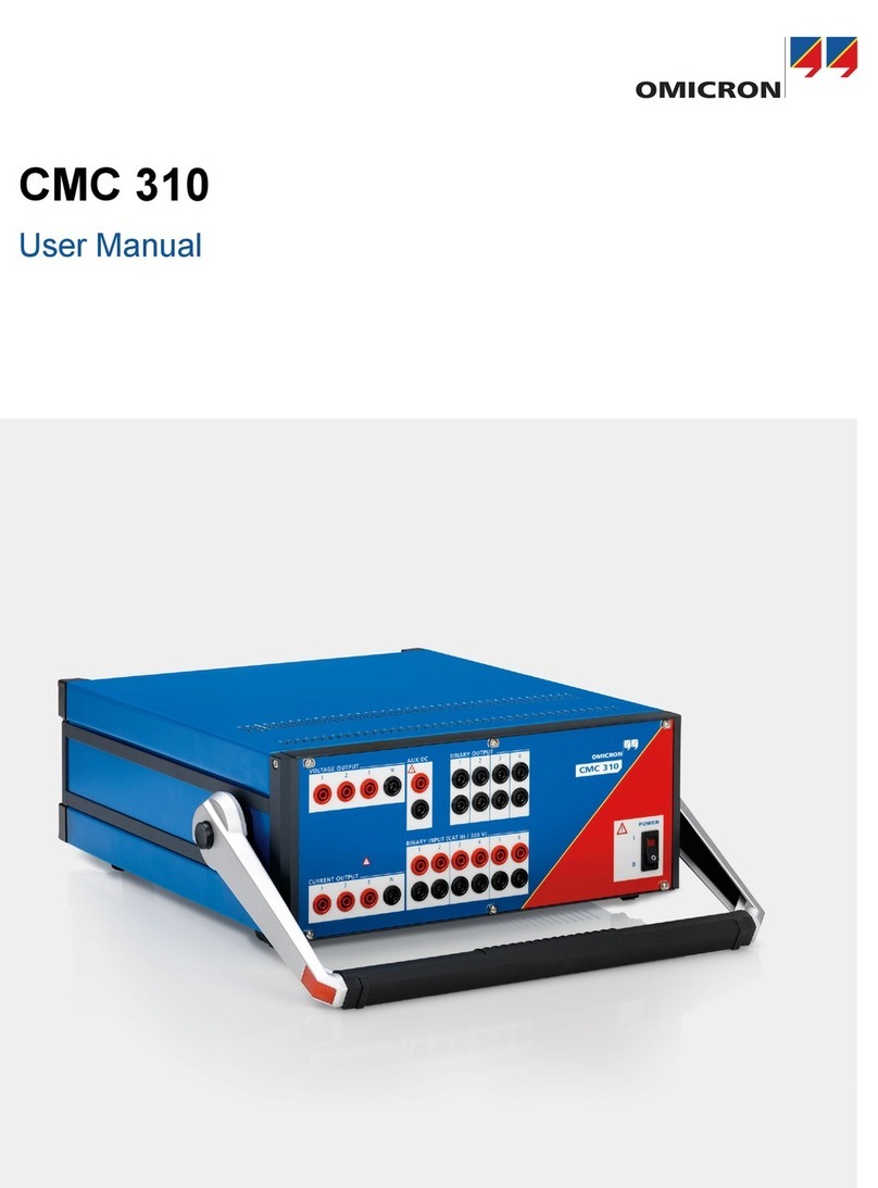
Omicron CMC 430 User manual

CMC 430
User Manual

Manual version: ENU 1169 05 02 - Year: 2019
© OMICRON electronics. All rights reserved.
This manual is a publication of OMICRON electronics. All rights including translation reserved.
Reproduction of any kind, for example, photocopying, microfilming, optical character recognition
and/or storage in electronic data processing systems, requires the explicit consent of OMICRON
electronics. Reprinting, wholly or in part, is not permitted.
The product information, specifications, and technical data embodied in this manual represent the
technical status at the time of writing and are subject to change without prior notice.
We have done our best to ensure that the information given in this manual is useful, accurate, up-to-
date and reliable. However, OMICRON electronics does not assume responsibility for any
inaccuracies which may be present.
The user is responsible for every application that makes use of an OMICRON product.
OMICRON electronics translates this manual from the source language English into a number of other
languages. Any translation of this manual is done for local requirements, and in the event of a dispute
between the English and a non-English version, the English version of this manual shall govern.
CMC 430 User Manual
2OMICRON

Contents
1 About this manual ............................................................................................................ 6
Safety symbols used .......................................................................................................... 6
2 Device overview ............................................................................................................... 7
2.1 Front panel ......................................................................................................................... 8
2.2 CONTROL INTERFACE section ........................................................................................ 9
2.2.1 Associate button ASC ........................................................................................................................ 9
2.2.2 Status LEDs ....................................................................................................................................... 9
2.2.3 Ethernet interfaces ............................................................................................................................. 10
2.2.4 USB ports ........................................................................................................................................... 10
2.2.5 External interface ............................................................................................................................... 10
2.2.6 Expansion ports ................................................................................................................................. 10
2.3 ANALOG/BINARY INPUT section ...................................................................................... 11
2.4 DC INPUT section .............................................................................................................. 11
2.5 BINARY OUTPUT section .................................................................................................. 11
2.6 VOLTAGE OUTPUT section ............................................................................................... 12
2.7 CURRENT OUTPUT section .............................................................................................. 13
2.8 AUX DC OUTPUT section .................................................................................................. 14
2.9 Generator combination socket ........................................................................................... 15
2.10 Power switch, mains socket, grounding terminal ............................................................... 15
2.11 Beeper ................................................................................................................................ 16
3 Technical data ................................................................................................................... 17
3.1 Specification conditions ...................................................................................................... 17
3.2 System clock accuracy ....................................................................................................... 18
3.3 Synchronization .................................................................................................................. 18
3.4 Current outputs ................................................................................................................... 19
3.4.1 Protection ........................................................................................................................................... 19
3.4.2 Accuracy ............................................................................................................................................ 20
3.4.3 Total harmonic distortion and noise (THD+N) .................................................................................... 21
3.4.4 Output power ..................................................................................................................................... 22
3.4.5 Duty cycle .......................................................................................................................................... 23
3.5 Voltage outputs ................................................................................................................... 24
Contents
OMICRON 3

3.5.1 Protection ........................................................................................................................................... 24
3.5.2 Accuracy ............................................................................................................................................ 25
3.5.3 Total harmonic distortion and noise (THD+N) .................................................................................... 26
3.5.4 Output power ..................................................................................................................................... 27
3.6 Generator combination socket ........................................................................................... 28
3.7 Simulated output power ...................................................................................................... 29
3.8 AUX DC output ................................................................................................................... 29
3.9 Binary outputs .................................................................................................................... 30
3.10 Analog/binary inputs ........................................................................................................... 30
3.10.1 Measurement concept ....................................................................................................................... 31
3.10.2 Analog input mode ............................................................................................................................. 31
3.10.3 Binary input mode .............................................................................................................................. 34
3.11 DC measurement input ...................................................................................................... 37
3.12 Communication interfaces (USB, Ethernet, expansion ports) ............................................ 38
3.12.1 Interfaces ........................................................................................................................................... 38
3.12.2 Power over Ethernet (PoE) power sharing ........................................................................................ 38
3.12.3 IEC 61850 protocols .......................................................................................................................... 39
3.12.4 Other communication protocols ......................................................................................................... 39
3.13 External interface ............................................................................................................... 40
3.13.1 Transistor outputs (binary outputs 11 ... 14) ....................................................................................... 40
3.13.2 Counter inputs 1 and 2 ....................................................................................................................... 41
3.14 Power supply specifications ............................................................................................... 41
3.15 Environmental conditions ................................................................................................... 42
3.16 Mechanical data ................................................................................................................. 42
3.17 Standards ........................................................................................................................... 42
3.18 How to read the specifications stated in this chapter ......................................................... 43
3.18.1 Calibration interval ............................................................................................................................. 43
3.18.2 Examples for amplifier accuracy ........................................................................................................ 43
4 Increasing the output power ........................................................................................... 45
4.1 Current outputs ................................................................................................................... 45
4.2 Voltage outputs ................................................................................................................... 45
4.3 Expansion Mode ................................................................................................................. 46
5 Troubleshooting ............................................................................................................... 48
5.1 Troubleshooting guide ........................................................................................................ 48
CMC 430 User Manual
4OMICRON
5.2 Potential errors, possible causes, remedies ...................................................................... 49
5.3 Overheating ........................................................................................................................ 49
6 Limited warranty ............................................................................................................... 50
7 Open source license information ................................................................................... 51
Support .............................................................................................................................. 52
Contents
OMICRON 5

1 About this manual
This user manual was written for professional specialists in electronics and electrical engineering. Its
purpose is to familiarize users with the CMC 430 test set hardware and its specifications.
This manual is supplemented by the "Safe use of the CMC 430" manual, on-site safety regulations
and existing national safety standards for accident prevention and environmental protection.
The CMC 430 test set requires a suitable control software or control device for operation. Please
consult the corresponding getting started manual or user documentation regarding the use of the
controlling software or device.
The "Safe use of the CMC 430" manual and the software manuals are supplied on CD/DVD
together with this user manual.
WARNING
Death or severe injury caused by high voltage possible.
► Operate the CMC 430 only after you have read and fully understood the "Safe use
of the CMC 430" manual.
Safety symbols used
In this manual, the following symbols indicate safety instructions for avoiding hazards.
WARNING
Death or severe injury can occur if the appropriate safety instructions are not observed.
NOTICE
Equipment damage or loss of data possible.
CMC 430 User Manual
6OMICRON

2 Device overview
The CMC 430 is a light-weight multipurpose test set with ultra low-drift signal generators and
measurement inputs. The CMC 430 reaches calibrator accuracy. All inputs and outputs can be
precisely synchronized to UTC using either the Precision Time Protocol (PTP) according to IEEE 1588
or the IRIG-B time code. Synchronization to GPS is possible using the CMGPS 588 accessory from
OMICRON.
The device has a very accurate time base with Stratum 3 specification and is thus able to provide very
high frequency accuracy even without external synchronization.
The CMC 430 is internally controlled by a very powerful digital processor platform that is responsible
for signal generation and measurement. It allows full support of the IEC 61850 protocol for signal
generation and measurement.
All interfaces and indicators of the CMC 430 are positioned on the front plate. Therefore, the CMC 430
can be operated in different positions according to the specific requirements of the application
environment.
The CMC 430 test set itself does not provide any control elements and requires a suitable control
software or control device for operation. The CMC 430 provides the following options for
communication with the controlling software or device:
• Ethernet
• USB
• Wi-Fi (requires a Wi-Fi adapter available from OMICRON)
Device overview
OMICRON 7

2.1 Front panel
This section provides an overview of the CMC 430 front panel elements. For detailed information
about an element → sections 2.2 to 2.11.
DC INPUT
High-accuracy analog
DC measurement input
(0 ... 20 mA or 0 ... 10 V)
VOLTAGE OUTPUT
6 x 150 V voltage outputs;
outputs 1 ... 3 are also
available on the generator
combination socket
BINARY OUTPUT
4 normally open
relay outputs
Generator combination socket
8-pole socket for current outputs 1 ... 3 and
voltage outputs 1 … 3
Power switch and
mains socket
ANALOG/BINARY INPUT
6 fully configurable and fully insulated
inputs. Configuration as binary input
or analog input is done in the
controlling software or the
controlling device
AUX DC OUTPUT
12 ... 264 V auxiliary DC
voltage supply; can be
used to supply test
objects with power
CONTROL INTERFACE
Associate button, status LEDs,
control interfaces, accessory interfaces.
All interfaces in this group are
touch-safe low voltage interfaces with
voltages < 60 V (DC)
CURRENT OUTPUT
3 x 12.5 A current outputs;
also available on the
generator combination socket
Grounding terminal
CMC 430 User Manual
8OMICRON

2.2 CONTROL INTERFACE section
All interfaces of this group are touch-safe and reinforced insulated against all other interfaces of the
device. The highest voltage provided is the 53 V Power over Ethernet (PoE) voltage available on the
Ethernet interfaces ETH1 and ETH2, and the accessory ports EXPANSION PORTS 1 ... 4.
2.2.1 Associate button ASC
The CMC 430 can be remotely controlled via an Ethernet or Wi-Fi network. Such
networks provide the possibility to connect more than just one CMC test set.
However, for safety reasons, the operator must be sure to control the test set in front
of him and not to accidentally control any other test set connected to the network.
Therefore, the controlling software will prompt the operator to press the Associate
(ASC) button in order to associate the test set to this computer, before the test set
can be used for the first time.
Please refer to the documentation of the controlling software for information on how
to perform an association.
Pressing the ASC button during the power-up sequence of the CMC 430 resets all
network settings of the CMC 430 (IP configuration, restrictions, Wi-Fi configuration,
etc.). Resetting the IP configuration of the Ethernet ports ETH1 and ETH2 to DHCP/
AutoIP can also be done in the controlling software without restarting the CMC 430.
2.2.2 Status LEDs
The LEDs indicate the system status of the CMC 430 as described below:
S1 (green) S2 (yellow) Status
OFF ON Normal operating state. The test set is ready for
operation and can be controlled by a suitable
software or device.
Blinking slowly OFF The test set is in recovery mode and waiting for a
firmware upload. Refer to the documentation of
the controlling software for information on how to
load a new firmware image to the CMC 430.
ON OFF The firmware upload to the CMC 430 is in
progress.
Blinking fast OFF The new firmware image uploaded before is
being written to the flash memory of the
CMC 430.
Do not turn off the CMC 430 during this state!
Device overview
OMICRON 9

2.2.3 Ethernet interfaces
10/100/1000Base-TX Ethernet ports with Power over Ethernet (PoE) capability. The
port LEDs indicate the link speed and will blink in case of traffic:
Link speed LED behavior
10 Mbps Yellow LED active
100 Mbps Green LED active
1000 Mbps Yellow and green LED active
Technical data → Communication interfaces on page 38.
2.2.4 USB ports
The PC port (USB type B) connects the CMC 430 to the USB port of the controlling
computer.
The USB port (USB type A) is currently used for the USB Wi-Fi adapter only. The
USB Wi-Fi adapter is required for connecting the CMC 430 to a Wi-Fi network. Only
use the Wi-Fi adapter available from OMICRON or a Wi-Fi adapter that is certified to
work with the CMC 430.
With future software upgrades, this port could also support other USB devices like
USB memory sticks, for example.
Technical data → Communication interfaces on page 38.
For best EMC immunity, we strongly recommend to exclusively use the
original high-quality USB cable supplied by OMICRON.
2.2.5 External interface
The external interface provides four transistor outputs and two high-speed
counter inputs. The counter inputs are mainly used for meter testing using
different adapters. This interface also allows the connection of the CMIRIG-B
accessory.
Technical data and pin assignment → External interface on page 40.
2.2.6 Expansion ports
The expansion ports allow the connection of up to four external accessories.
Technical data → Communication interfaces on page 38.
CMC 430 User Manual
10 OMICRON

2.3 ANALOG/BINARY INPUT section
The six fully configurable inputs can be used as binary or analog inputs. Each
input is reinforced insulated from all other inputs and the rest of the test set.
The inputs can be configured to the following functionality:
• Analog input (configurable voltage range 10 mV, 100 mV, 1 V, 10 V, 100 V,
600 V; sampling frequency 40 kHz or 10 kHz; time synchronization
capabilities for synchronized measurement and synchrophasor
measurement; current measurement using a C-Shunt or a CP 30 current
clamp)
• Binary input for wet contacts (configurable threshold from -600 V to +600 V)
• Binary input for dry contacts (relay contacts)
• Binary input for triggering on the presence of AC signals (with configurable
threshold)
• Usage of debounce and/or deglitch filters for binary inputs
Binary input 6 can also be used to synchronize the phase and frequency of the
voltage outputs to a reference input signal of 15 ... 70 Hz.
Technical data → Analog/binary inputs on page 30.
2.4 DC INPUT section
This universal DC measurement input can be configured for voltage or current
measurement. The high-accuracy and low-drift measurement input can be used
to test transducers or to measure the output of other sensor signals.
The input can be configured to one of the following ranges: 1 mA, 20 mA,
10 mV, 100 mV, 1 V or 10 V.
Technical data → DC measurement input on page 37.
2.5 BINARY OUTPUT section
The four potential-free normally open relay contacts can switch AC or DC
currents of up to 8 A.
Technical data → Binary outputs on page 30.
NOTICE
Equipment damage possible.
► Observe the power limits stated in section Binary outputs on page 30
when switching DC currents.
Device overview
OMICRON 11

2.6 VOLTAGE OUTPUT section
Six voltage outputs for voltages up to 150 VRMS or 212 VDC.
The voltage outputs are galvanically separated from all other connections of
the CMC 430. The two black N sockets are galvanically connected to each
other.
The voltage outputs are protected against short-circuit and overload conditions.
The voltage amplifier is additionally protected against overtemperature.
An LED in the upper left corner and the internal beeper indicate the occurrence
of overload conditions and that voltage is applied at one or more voltage
outputs (beeper configuration → Beeper on page 16).
Overload conditions are also indicated in the controlling software or device.
LED state Description
Red Voltage amplifier is active
Red blinking Overload or short circuit
OFF Voltage amplifier is inactive
NOTICE
Equipment damage possible.
Infeed of voltages from external sources may damage the voltage outputs.
Technical data → Voltage outputs on page 24.
The voltage outputs 1 ... 3 are also available on the generator combination
socket → Generator combination socket on page 15.
CMC 430 User Manual
12 OMICRON

2.7 CURRENT OUTPUT section
Two ranges can be configured for the three current outputs: 1.25 A or 12.5 A.
The current outputs are galvanically separated from all other connections of the
CMC 430.
The current outputs are protected against open-circuit and overload conditions.
The current amplifier is additionally protected against overtemperature.
An LED in the upper left corner and the internal beeper indicate the occurrence
of overload conditions and that current is issued at one or more current outputs
(beeper configuration → Beeper on page 16).
Overload conditions are also indicated in the controlling software or device.
LED state Description
Red Current amplifier is active
Red blinking Overload (burden too high)
OFF Current amplifier is inactive
NOTICE
Equipment damage possible.
Infeed of currents from external sources may damage the current outputs.
Only in the non-operative state, the current outputs are protected by short-
circuit relays against external infeed.
Technical data → Current outputs on page 19.
The current outputs are also available on the generator combination socket →
Generator combination socket on page 15.
Device overview
OMICRON 13

2.8 AUX DC OUTPUT section
The output AUX DC OUTPUT can be used to supply test objects with DC
voltage. The output voltage can be configured to 12 ... 264 V in the CMC 430
Web Interface or the controlling software or device (accessing the Web
Interface → Getting Started manual of the controlling software).
The output AUX DC OUTPUT is galvanically separated from all other
connections of the CMC 430.
The output is protected against short-circuit and overload conditions. The
voltage amplifier is additionally protected against overtemperature.
An LED in the upper left corner and the internal beeper indicate the occurrence
of overload conditions and that voltage is applied at the output (→ Beeper on
page 16). Overload conditions are also indicated in the controlling software or
device.
LED state Description
Red Output is active
Red blinking Overload or short circuit
20 s time period without voltage output after start-up
→ "Aux DC voltage output after start-up" below.
OFF Output is inactive
Aux DC voltage output after start-up
In the controlling software or device, the output AUX DC OUTPUT can be
programmed to automatically output a configured voltage after switching the
CMC 430 on. If so:
• No voltage is output for the first 20 s after the start-up of the CMC 430.
• The LED blinks red and the CMC 430 issues an intermittent beep (0.1 s on/
0.5 s off) during this period of time.
• Upon expiry of this 20 s period, the configured voltage is available at output
AUX DC OUTPUT. The LED lights continuously and the beeper falls silent.
NOTICE
Damaging of connected equipment possible.
The AUX DC OUTPUT can be programmed to output voltage without user
intervention directly after start-up.
► Check the voltage configured for this output before connecting a device.
NOTICE
Equipment damage possible.
Infeed of voltages from external sources may damage the output.
Technical data → AUX DC output on page 29.
CMC 430 User Manual
14 OMICRON

2.9 Generator combination socket
The voltage outputs 1 ... 3 and the current outputs 1 ... 3 are also wired to the
8-pole generator combination socket. This socket is intended to simplify the
connection of test objects to the CMC 430.
Please refer to the descriptions of the voltage and current outputs in sections
VOLTAGE OUTPUT on page 12 and CURRENT OUTPUT on page 13.
NOTICE
Equipment damage possible.
Infeed of voltages or currents from external sources may damage the
voltage and/or current outputs.
Technical data and pin assignment → Generator combination socket on
page 28.
2.10 Power switch, mains socket, grounding terminal
ON/OFF switch and mains socket.
Nominal voltage: 100 ... 240 VAC, 50/60 Hz.
Technical data → Power supply specifications on page 41.
Use the grounding terminal to ground the test object or to provide an additional
ground connection for the test set.
Device overview
OMICRON 15

2.11 Beeper
A beeper indicates the output of voltages and/or currents. The behavior of the beeper can be
configured in the CMC 430 Web Interface (accessing the Web Interface → Getting Started manual of
the controlling software).
Beeper mode Description
Beeper enabled The beeper is enabled by default. Two modes can be selected:
• One short beep (0.1 s) at the beginning of the voltage/current output
on the outputs VOLTAGE OUTPUT 1 ... 6,
CURRENT OUTPUT 1 ... 3 or AUX DC OUTPUT
• Intermittent beep (0.1 s on/2 s off) during the output of voltages/
currents on the outputs VOLTAGE OUTPUT 1 ... 6 and/or
CURRENT OUTPUT 1 ... 3; short beep at the beginning of the
voltage output on output AUX DC OUTPUT
Overload indication:
Intermittent beep (0.1 s on/0.5 s off) in case of an overload on one of
the outputs VOLTAGE OUTPUT 1 ... 6, CURRENT OUTPUT 1 ... 3 or
AUX DC OUTPUT
Beeper disabled The beeper can be disabled temporarily.
The output AUX DC OUTPUT can be programmed to automatically output a configured
voltage after the start-up of the CMC 430. If so, the CMC 430 issues an intermittent beep
(0.1 s on/0.5 s off) for a period of 20 s after start-up to indicate that voltage will be applied at
this output upon expiry of this period. This warning beep cannot be configured or disabled!
→ AUX DC OUTPUT section on page 14
If you reduce the voltage setting for the AUX DC OUTPUT from a high value of, for example
220 V, to a low value of, for example 24 V, and you have enabled the beeper in the CMC 430
Web Interface, you will hear an intermittent beep while the voltage reduces from the high to
the low value.
CMC 430 User Manual
16 OMICRON

3 Technical data
This chapter contains the complete specifications for the CMC 430. These specifications characterize
the behavior of the device under different operating and environmental conditions. The values stated
in this chapter are
• absolute 1- and 2-year specifications,
• relative 24-hour specifications,
• or typical or guaranteed specifications valid over the entire lifetime of the CMC 430.
Absolute 1- and 2-year specifications are absolute accuracy values met by at least 99 % of all
CMC 430 test sets even at the end of the specified time period after delivery of new devices or factory
calibration of used devices. → Calibration interval on page 43.
Relative 24-hour specifications exclusively define the short-term drift within 24 hours relative to an
initial value under otherwise stable operating conditions (temperature, humidity, and load).
Example: A 24-hour specification of 0.015 % + 0.05 % means that an output value of, for example,
50.01 V available at the beginning of a 24-hour period may drift by 15 mV within these 24 hours to an
output value of 50.025 V or 49.995 V.
This may be useful to compare test objects or to increase the accuracy by comparing the accuracy to
a more stable reference. One possible application for this could be to check the accuracy of the
CMC 430 against a more stable reference, and then calibrate it for up to 24 hours using the 24-hour
specification and the measured deviation.
Specifications marked to be typical values represent characteristic performance that will be met by
90 % of all CMC 430 test sets produced if the test sets are operated within the conditions given in
section 3.1. Typical specifications are not tested and not warranted.
Specifications marked to be guaranteed represent guaranteed performance met by all CMC 430 test
sets if the test sets are operated within the conditions given in section 3.1.
3.1 Specification conditions
Unless stated otherwise, the specifications given in this chapter are valid at the terminals of the
CMC 430 and under the following conditions:
• After a warmup period of 30 minutes
• At a temperature of 23 °C ± 5 °C
• At a relative humidity < 80 %
• If regular calibration is performed every 1 or 2 years, depending on the customer requirements
Technical data
OMICRON 17

3.2 System clock accuracy
All signals generated or measured by the CMC 430 refer to a common internal time base that is
specified as follows:
Characteristic Specification
Clock performance Stratum 3 (ANSI/T1.101-1987)
Frequency drift (over time)
24 hours
20 years
< ±0.37 ppm (±0.000037 %)
< ±4.60 ppm (±0.00046 %)
Frequency drift (over temperature range) < ±0.28 ppm (±0.000028 %)
Frequency resolution (signal generation) < 5 μHz
3.3 Synchronization
Synchronization of system clock
By synchronizing the system clock to an external time base, the system clock accuracy can be
improved up to the level of the external time base. Synchronizing the system clock additionally makes
the absolute time available in the system to tag measurement results, start distributed tests at the
same time, and generate and measure synchrophasors.
The following specifications refer to the internal time base. For the absolute time accuracy of the
outputs and inputs, the inherent error of the respective channel itself has to be added.
Characteristic Specification
IEEE 1588-2008 (v2)
Offset (UTC)
Pulling range
Supported profiles
Supported sources
Error < ±1 µs
±100 ppm (±0.01 %)
IEEE C37.238-2011 (Power Profile)
IEC/PAS 61850-9-3: Communication Networks and Systems for
Power Utility Automation – Part 9-3: Precision Time Protocol Profile
for Power Utility Automation (Utility Profile)
OMICRON CMGPS 588 or any Precision Time Protocol source
(PTP grandmaster clock)
IRIG-B
Offset (UTC)
Pulling range
Supported sources
Error < ±5 μs
±100 ppm (±0.01 %)
Third-party IRIG-B sources with OMICRON CMIRIG-B accessory
Synchronization of voltage and current output signals
The phase and frequency of the voltage and current outputs can be synchronized to a reference input
signal of 15 ... 70 Hz applied to binary input 6. In contrast to the synchronization of the system clock,
this kind of synchronization influences the frequency and phase of the signal generation directly.
CMC 430 User Manual
18 OMICRON

The possible accuracy depends on the quality of the synchronization signal because the
synchronization uses the zero crossings of the signal.
3.4 Current outputs
Characteristic Specification
Ranges Range I: 0 ... 1.25 A
Range II: 0 ... 12.5 A
Frequency range
Frequency range
Transient playback & power quality signals
0 ... 1 kHz
0 ... 3 kHz
Configurations (AC)
L-N
L-N
LLL-N (parallel)
L-L (series)
3 x 1.25 A
3 x 12.5 A
1 x 37.5 A
1 x 12.5 A
Configurations (DC)
L-N
L-N
LLL-N (parallel)
L-L (series)
3 x ±1.25 A
3 x ±12.5 A
1 x ±37.5 A
1 x ±12.5 A
Resolution per channel (DC)
1.25 A range
12.5 A range
< 70 µA
< 700 µA
3.4.1 Protection
1 2 3N
~~~
The current outputs are protected against open-circuit and overload conditions. The current amplifier
is additionally protected against overtemperature.
NOTICE
Equipment damage possible.
Infeed of currents from external sources may damage the current outputs. Only in the non-operative
state, the current outputs are protected by short-circuit relays against external infeed.
Technical data
OMICRON 19

3.4.2 Accuracy
The specifications given in this section are valid for single-channel current output. When using the
parallel output configuration (1 x 37.5 A), the errors of the individual channels have to be added.
The phase and amplitude accuracy of the current amplifier depends on the connected burden. For
higher burdens, the influence of the output impedance needs to be considered.
Unless stated otherwise, the specification is valid within the following limits:
Range Calibration burden Burden range
1.25 A 0.5 Ω 0 ... 1 Ω
12.5 A 0.25 Ω 0 ... 0.5 Ω
Amplitude accuracy
The 24-hour stability specifications apply for a stable burden. In order to obtain the specified amplitude
accuracy at currents below 6 A, the amplifier has to cool down for at least 90 seconds after the output
of currents above 6 A.
Range Frequency Accuracy
±(% of set value + % of range)
Temperature coefficient
±(% of set value + % of rg.)/°C
beyond 23 °C ± 5 °C
24 hours 1 year 2 years
1.25 A 50/60 Hz 0.02 + 0.005 0.04 + 0.01 0.07 + 0.01 0.0015 + 0
10 Hz ... 100 Hz - 0.04 + 0.01 0.07 + 0.01
100 Hz ... 1 kHz - 0.25 + 0.01 0.23 + 0.01
DC - 0.04 + 0.015 0.07 + 0.015 0.0015 + 0.0050
12.5 A
(Iset ≤ 6 A)
50/60 Hz 0.02 + 0.005 0.04 + 0.01 0.07 + 0.01 0.0015 + 0
10 Hz ... 100 Hz - 0.04 + 0.01 0.07 + 0.01
12.5 A 10 Hz ... 100 Hz - 0.08 + 0.01 0.11 + 0.01
100 Hz ... 1 kHz - 0.35 + 0.01 0.38 + 0.01
DC - 0.08 + 0.015 0.11 + 0.015 0.0015 + 0.0005
Note: If the test object evaluates AC and DC components, the offset needs to be considered in the
RMS value. The offset is calculated from the DC specification with a set value of zero. The effect is
negligible for currents higher than 1 % of the output range.
CMC 430 User Manual
20 OMICRON
Table of contents
Other Omicron Test Equipment manuals

Omicron
Omicron CPC 100 User manual

Omicron
Omicron CPC 100 User manual

Omicron
Omicron CP CR500 User manual

Omicron
Omicron CMC 356 User manual

Omicron
Omicron CP TD1 User manual

Omicron
Omicron CPC 100 User manual

Omicron
Omicron Light HUB Ultra User manual

Omicron
Omicron MPD 800 User manual

Omicron
Omicron CPC 100 User manual

Omicron
Omicron CMC 850 User manual
Popular Test Equipment manuals by other brands

Apera Instruments
Apera Instruments COND5 manual

WatchGas
WatchGas BAT-1 user manual

Platinum Tools
Platinum Tools Net Chaser TNC950AR user manual

LMF Clima
LMF Clima HPH series Installation, operation and maintenance manual

Thermo Scientific
Thermo Scientific HAAKE Viscotester iQ instruction manual

Draper
Draper RPT1 Instructions for use